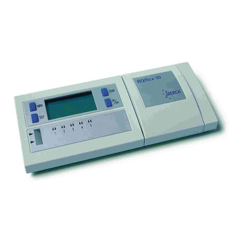
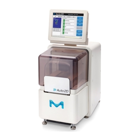
Merck Supelco TLC Explorer User manual

TLC Explorer
Documentation System
1.52610.0001
Version 2023/11
Operational User Manual

3Version 1.0 – 2023/11
1
2
3
4
5
6
7
8
9
10
11
12
1 Introduction .............................................................................................................. 6
1.1 Intended Use of TLC Explorer ................................................................................ 6
1.2 Safety and Handling Instructions ........................................................................... 6
1.2.1 Do NOT Operate the TLC Explorer if … ........................................................... 7
1.2.2 Installation Requirements ............................................................................ 8
1.2.3 Ultraviolet Radiation Exposure...................................................................... 8
1.2.4 General Notes on Handling .......................................................................... 9
1.2.5 User Management and Information Security................................................... 9
1.3 A Short Introduction to TLC..................................................................................10
1.3.1 The TLC Working Principle...........................................................................10
1.3.2 Retardation Factor Rf..................................................................................11
1.4 About this Manual ...............................................................................................11
2 Get to Know Your TLC Explorer................................................................................ 12
2.1 TLC Explorer Front ..............................................................................................12
2.1.1 F1 - Power Button .....................................................................................12
2.1.2 F2, F3, F4 - Illumination Buttons and Indicators ............................................13
2.1.3 F5, F6 - Drawer and ‘Drawer open’ Indicator .................................................13
2.1.4 F7, F8 - Inspection Window and Shutter Slider ..............................................14
2.2 TLC Explorer Back...............................................................................................14
2.2.1 B1 – USB-C Port for Power Supply ...............................................................14
2.2.2 B2, B3 - USB-A Ports .................................................................................14
2.2.3 B4 - Ethernet Port .....................................................................................15
2.2.4 B5 - WiFi Antenna Connector ......................................................................15
2.2.5 B6 - Serial Number....................................................................................15
2.2.6 B7 - Back Cover ........................................................................................15
2.2.7 B8 - Illumination Unit.................................................................................15
2.3 TLC Explorer Baseplate........................................................................................16
2.3.1 P1 - Plate Area..........................................................................................16
2.3.2 P2 - Frame ...............................................................................................16
2.3.3 P3, P4 - Alignment Pin and Socket ...............................................................16
2.4 Accessories ........................................................................................................17
2.4.1 A1 - WiFi Antenna .....................................................................................17
2.4.2 A2, A3 - Power Adapter and Cords ...............................................................17
2.4.3 A4 - Power Bank .......................................................................................18
3 First Use .................................................................................................................. 19
3.1 Unpacking and Scope of Delivery ..........................................................................19
3.2 Setting up for Safe Operation ...............................................................................20
3.3 Powering Up and a ‘First Look’ on Your Plate...........................................................20
3.4 Connecting Your Laptop .......................................................................................21
3.5 Creating a First User ...........................................................................................23
3.6 Powering Down...................................................................................................25
Content

54 Version 1.0 – 2023/11Version 1.0 – 2023/11
1
2
3
4
5
6
7
8
9
10
11
12
1
2
3
4
5
6
7
8
9
10
11
12
4 Operational Guide..................................................................................................... 26
4.1 TypicalWorkow.................................................................................................26
4.1.1 Main Menu.................................................................................................28
4.2 Device Preparation..............................................................................................28
4.3 Visual Inspection ................................................................................................29
4.4 Image Capture ...................................................................................................29
4.5 Loading an Existing Image Set..............................................................................32
4.6 Select and Edit Plate ...........................................................................................32
4.7 DeneTracks .....................................................................................................35
4.8 Creating an Evaluation ........................................................................................37
4.9 Annotate Plate Image..........................................................................................39
4.10 Plot and Compare Track Densitograms....................................................................40
4.10.1 Plotting Densitograms ...............................................................................40
4.10.2 Adding Names or Annotations to Spots ........................................................41
4.11 Quantitative Analysis ...........................................................................................43
4.11.1 Preparing a Quantitative Evaluation.............................................................43
4.11.2 Reading Quantitative Measurements and Fine Tuning .....................................46
4.12 Export Images and Evaluation Results ....................................................................47
4.12.1 ‘Export Original Cropped Images’ (all tabs)...................................................48
4.12.2 ‘Export Images as Displayed’ (all tabs) ........................................................48
4.12.3 ‘Export Annotations’ (‘Annotations’ only) ......................................................48
4.12.4 ‘Export Spots’ (‘Annotations’ and ‘Comparison’).............................................49
4.12.5‘ExportComparison’(‘Comparison’and‘Quantication’) .................................49
4.12.6‘ExportQuantication’(‘Quantication’only) ................................................49
4.12.7 Download or Save Exported Files ................................................................49
4.13 Generate Reports on Evaluations ...........................................................................50
4.14 Manage Files and Image Sets................................................................................51
4.14.1 Exporting Image Sets and Downloading Images............................................52
4.14.2 Copy or Import Image Sets ........................................................................53
4.14.3 Deleting Image Sets..................................................................................53
4.15 Reset or Shut Down Device...................................................................................53
5 User Management and Device Settings..................................................................... 54
5.1 Changing Active User ..........................................................................................55
5.2 Adding and Deleting Users ...................................................................................55
5.3 Device Name and Serial Number...........................................................................56
5.4 Time and Date....................................................................................................56
5.5 Digital Illumination Correction ..............................................................................56
5.6 Stray-light Detection ...........................................................................................56
6 Backup and Data Migration....................................................................................... 57
6.1 Generating a Backup ...........................................................................................57
6.2 Recovering Backup..............................................................................................58
6.3 MigratingUserDatatoadierentTLCExplorer.......................................................58
7 Software Updates ..................................................................................................... 59
7.1 Current Software Version .....................................................................................59
7.2 Obtaining Software Update...................................................................................60
7.3 Installing Update ................................................................................................60
7.4 Recovering Previous Software Version....................................................................61
7.5 Factory Reset .....................................................................................................61
8 Connecting the TLC Explorer..................................................................................... 62
8.1 TLC Explorer’s own WiFi.......................................................................................63
8.2 Integrating in LAN via Ethernet Cable ....................................................................63
8.3 Integrating into an existing WiFi Network ...............................................................64
8.4 Resetting Network Connection ..............................................................................64
8.5 Mounting TLC Explorer as Network Location (SMB) ..................................................64
9 Troubleshooting ....................................................................................................... 65
9.1 Identifying Errors................................................................................................65
9.2 Possible Remedies and Solutions...........................................................................66
10 Cleaning, Maintenance, and Decommissioning ....................................................... 68
10.1 Cleaning ............................................................................................................68
10.2 Contact Technical Support ....................................................................................68
10.3 Ordering Accessories and Replacement Parts...........................................................69
10.4 Replacing the Illumination Unit..............................................................................70
10.5 Decommissioning, Storage, and Disposal ................................................................71
11 Glossary ................................................................................................................. 72
12 Technical Data........................................................................................................ 73
12.1Devicemeasuresandspecications .......................................................................73
12.2 Illumination spectra.............................................................................................74
Content Content

7Version 1.0 – 2023/11
1
2
3
4
5
6
7
8
9
10
11
12
6Version 1.0 – 2023/11
2
3
4
5
6
7
8
9
10
11
12
1 Introduction - 1.2 Safety and Handling Instructions
1.1 Intended Use of TLC Explorer
1 Introduction
The TLC Explorer is designed to document and evaluate thin-layer chromatographic plates. It
oersasafe,fastandexiblewaytovisuallyinspectanddigitallyrecordimagesofTLCplates
aftertheirchromatographicdevelopmentworkowinthelaboratory.Fordetectingdierent
substanceclasses,thedevicecontainsthreedierentLEDlightsourceswhichilluminatethe
plates from above in direct-light mode:
• White light is used for the detection of visible, colored substances on thin-layer chromato-
grams.
• UV-A(366nm)istypicallyusedtostimulateuorescence.Underthisillumination,uorescent
substancesandobjectsappearasbright,dierentcoloredspotsonadarkbackground.
Itcanalsobeusedforplateswhicharepre-coatedwiththespecialuorescenceindicator
F366. The substances, in this case, appear as dark or colored spots on a bright background.
Otheruorescenceindicators,likeF254,donotuoresceunderthislightandthereforedonot
interfere with the measurement.
• UV-C (254 nm) illumination is used almost exclusively for thin-layer chromatograms. Sub-
stances which absorb this light appear as dark spots on a bright background if the plate is
pre-coatedwithanappropriateF254uorescentindicator.
Recorded plate images can be evaluated to generate reports or export the data for further
processing with other systems.
The TLC Explorer was developed for use in the laboratory and to be operated by trained and
skilled users to perform thin-layer chromatography. Only fully dried TLC plates with a maximum
size of 20 x 20 cm should be used.
Please note, that any other use than the intended one described above invalidates claims under
warranty.
1.2 Safety and Handling Instructions
Operational safety has been a primary objective when developing the TLC Explorer. However, it
can only be guaranteed if the device is operated strictly according to the instructions given in this
manual.Furthermore,anyoperationconictingwiththesafetyinstructionsgiveninthismanual
may invalidate claims under warranty. All personnel responsible for installation, use and mainte-
nance must therefore read this operating manual carefully before working with the TLC Explorer
and keep it at hand for later reference.
1.2.1 Do NOT Operate the TLC Explorer if …
Before connecting the TLC Explorer to a power supply, ensure none of the following applies:
• The device has been stored under adverse conditions over a lengthy period of time.
• The device has been damaged in transport or by incorrect handling (e.g. dropped during
transport or contact with liquids).
• Any part of housing, front unit, back cover, drawer, or Baseplate is wet, damaged, or deformed.
• The UV protection inspection window is missing, damaged or deformed.
• Thedevicedoesnotstandonadry,at,andstablesurface.
• The drawer cannot be extended fully or does not close correctly.
• The foam pad inside the device (used as transport protection) has not been removed.
• The back cover is not mounted properly, and all four screws fastened.
• Any connector (USB-C, USB-A, Ethernet, and WiFi Antenna) or cable is wet, damaged, or
deformed.
• The power supply is none of the recommended two adapters (USB-C power adapter DELL
HA65NM170 or power bank DELL PW7018LC).
• Thedeviceissignicantlycolderthanitsenvironment,suchthathumiditycouldcondensate
and damage electric circuits (please wait until device reaches room temperature).
• Thedeviceenvironmenttemperatureliesoutsidethespecied15-40°Cortherelativehu-
midityoutsidethespecied20-80%.
• The device is, or has been, exposed to acidic, alkaline, solvent vapors or other gasses that
may cause corrosion.
• Liquids, or other materials, have been spilled on or in the device. If so, remove them immedi-
ately. Make sure that the device is not damaged and completely dry before using it again.
If you expect any of the issues above apply to your device, do not connect, power up or operate.
For questions on how to proceed, please contact the supplier of your TLC Explorer or visit the TLC
Explorerservicesiteusingthelinkingure1.1:
Figure 1.1: Find the TLC Explorer service page at:
https://sigmaaldrich.com/TLCservice
1 1

98 Version 1.0 – 2023/11Version 1.0 – 2023/11
1
2
3
4
5
6
7
8
9
10
11
12
1
2
3
4
5
6
7
8
9
10
11
12
1 Introduction - 1.2 Safety and Handling Instructions
1 1
1 Introduction - 1.2 Safety and Handling Instructions
1.2.2 Installation Requirements
For a safe and reliable operation, please follow the following guidelines when setting up the de-
vice in your laboratory:
• Thedevicemustbeinstalledonaatanddrylabbenchsuitabletosupporttheweightof
about 10 kg of the device.
• Do not expose the instrument to any strong vibration or shock.
• Protect the instrument from excessive dust.
• Locate the TLC Explorer, cables, and, if applicable, the power bank, at a safe distance from
heating sources (e.g. gas burners, electric heaters or ovens), chemical substances (e.g. sol-
vents) or other devices which could cause damage to them.
• To power the device, use only the USB-C power adapter DELL HA65NM170 or power bank
DELL PW7018LC, and connect them to the USB-C port at the back of the device.
• Connect the power source to a grounded outlet located within 2 meters of the device, follow-
ing the regulations for the use of electronic devices in your laboratory.
• Thelinevoltageattheuserlocationmustmeetthespecicationsstatedonthepoweradapter.
• Donotplacetheinstrumentnearequipmentthatgeneratesintensemagneticeldssuchas
electric welding equipment, high frequency furnaces, pole transformers, etc.
• Connecttheinstrumenttopowerlinesthatarefreefromsuddenchangesorvoltageuctua-
tions.
• In case power motor driven equipment (such as a stirrer or shaker) must be connected to the
same power line as your TLC Explorer, ensure that a noise reduction unit is installed.
• Ensurethatcablesarearrangedinawaythattheyneitherposearisktothestaworking
with, and around, the device, nor that they are accidentally drawn from their respective sock-
ets.
• There must be enough space in front of the device to open the drawer completely and handle
the Baseplate in a safe and convenient way.
• Place the device on a height that allows users to conveniently look through the inspection win-
dow.Avoidreectionsofexternallightsourcesontheglassfrontthatdisturbtheviewthrough
the inspection window.
• The device should only be used in an environment and operated in a manner that meets all of-
ciallabsafetyrequirements.
1.2.3 Ultraviolet Radiation Exposure
Ultravioletradiation,usedinTLCplateEvaluationtostimulateuorescence,cancausedamage
to eyes and skin. Safety regulations in most countries therefore demand that eyes and skin are
protected from hazardous UV radiation. The TLC Explorer incorporates several safety measures to
ensure that no UV-A or UV-C light leaks from the device when used as described in this manual.
Under no circumstances try to circumvent these safety measures!
• Only look at TLC plates under UV illumination through the UV-protection inspection window.
• Ensure the inspection window is not damaged or deformed.
• Before activating UV illumination, check that the drawer and back cover are correctly closed
and not damaged.
• Never operate the illumination unit outside the TLC Explorer.
• Follow general laboratory safety regulations for working with UV light.
1.2.4 General Notes on Handling
• Ensure the device has at least 30 seconds available to completely shut down before unplug-
ging the power supply – similar to a desktop computer.
• Only TLC Plates without solvent residue can be documented – please ensure the TLC Plate is
completely dry after the previous chromatographic development or derivatization step.
• Do not place objects higher than 8 mm on the Baseplate, as it might damage the device when
closing the drawer and would be out of focus for image capture.
• Never lift or carry the device by holding the drawer handle. Instead, hold it on the bottom and
grab the rubber feet to prevent it slipping out of your hands.
• Close the drawer whenever the device is not in use to avoid damages and contamination.
• When the TLC Explorer is being transported, the TLC Explorer must be closed, the Baseplate
removed. No TLC plate should be inserted.
• Only attach FAT32 formatted USB sticks to USB-A ports for backups and updates. Do not use
external HDDs nor any other media connected via a cable.
• Except for the replacement of the illumination unit (see section 10.4), the TLC Explorer shall
only be opened, adjusted, or repaired by specialist personnel authorized by the manufacturer.
Noncompliance invalidates any claim under warranty.
• Retain the original packaging, including the inner packaging, to protect the instrument against
physical impact if it must be transported; especially for warranty claims. Please note, that
damage caused by improper transport voids all warranty claims.
1.2.5 User Management and Information Security
It is assumed that the devices are placed in laboratories where physical access is limited to
authorizedstaonly.Togiveprioritytoasmoothandecientlaboratoryworkow,theTLC
Explorer,therefore,featuresnomeanstorestrictaccesstospecicusersorprotectdatawith
passwords or encryption. User accounts mainly serve to structure recorded data. There is no ad-
ministration account with special privileges.
Any person with physical access or network connection to the device can
• create new users
• delete or login as an existing user
• access and delete all stored data
• initiate a restart or shut down of the instrument
• change device settings (incl. connectivity parameters)
• conduct a factory reset.
Depending on how you choose to integrate the TLC Explorer in your IT environment (see section
8), a large group of users may have access to your device(s). If the TLC Explorer is connected to
a LAN or a WiFi network, usually everyone with access to that network can also open the user in-
terfaceandloginasanexistingornewuser(seesection3.4).Ifcondentialityisaconcern,copy
the respective data to your desktop or tablet, and then remove it from the TLC Explorer.
• Plan and test carefully the TLC Explorer connectivity settings to ensure only authorized and
trained personnel have access.
• Download or copy your data to a memory stick and then save it at an external storage loca-
tion. Do not use the TLC Explorer for permanent data storage.
• Onlyapplyveriedupdatesfromthemanufacturer.
• OnlyattachUSBmemorysticks(ashdrives)youarecertaindonotcontainmalicioussoft-
ware.

1110 Version 1.0 – 2023/11Version 1.0 – 2023/11
1
2
3
4
5
6
7
8
9
10
11
12
1
2
3
4
5
6
7
8
9
10
11
12
1 1
1 Introduction - 1.3 A Short Introduction to TLC 1 Introduction - 1.3 A Short Introduction to TLC - 1.4 About this Manual
1.3 A Short Introduction to TLC
Thin-layer chromatography (TLC) is a fast, easy-to-use, and highly versatile separation technique
forqualitativeandquantitativeanalysis.Itisidealforrapididentication,screening,andreac-
tion monitoring. Its high matrix tolerance and the possibility to separate many samples in parallel
makesTLChighlytimeandcost-ecient.Itiswidelyusedforbothqualitativeandquantitative
sample analysis. TLC can be used to analyze virtually any substance class, including pesticides,
steroids, alkaloids, lipids, nucleotides, glycosides, carbohydrates, and fatty acids.
1.3.1 The TLC Working Principle
Thegeneralthin-layerchromatographyprocessissimple,asdemonstratedgure1.2.
Supporting
Measures
Sample
Preparation
Choice of stationary
and mpbile phases
in TLC process
Sample Application
Pre-rinsing the layer
Chromatogram
Development
Pre-conditioning
the layer
Pre-Post
chromatogram
Development
Evaluation
Main
Operations
Optional
Operations
Figure 1.2: TLC process: preparation of of the layer (plate), sample preparation,
choice of stationary phase, choice of mobile phase, sample application,
development, derivatization, documentation
Thekeystepintheworkowisthechromatographicprocess.TLCisbasedontheclassicchro-
matographyprinciplewheremixturecomponentsareseparatedbetweenaxedstationaryphase
andaliquidmobilephasebydierentialanitiesbetweenthetwophases.Thisisusuallyathin
adsorbent material layer, like silica gel or aluminum oxide, coated onto an inert plate surface,
typically glass, plastic, or aluminum. The sample is spotted onto one end of the TLC plate (start
line) and placed vertically into a closed chamber with an organic solvent (mobile phase). The mo-
bile phase travels up the plate by capillary forces, and sample components migrate varying dis-
tancesbasedontheirdierentialanitiestothestationaryandmobilephases.Whenthesolvent
reachesaspecicheightattheupperthirdoftheplate,theplateisremovedfromthedeveloping
chamber and dried. The separated components appear as spots on the plate and the retardation
factor (Rf) of each component is assessed.
1.3.2 Retardation Factor Rf
Rfisdenedasthedistancetravelledbyanindividualcomponentdividedbythetotaldistance
travelled by the solvent; its value is always between zero and one. To avoid the decimal point,
the retardation factor can also be multiplied by 100 and then is referred to as hRf.
In general, the stronger a compound binds to the stationary phase adsorbent, the slower it
migrates up the TLC plate. As TLC adsorbents are typically polar, non-polar compounds tend to
travel more rapidly up the plate, resulting in a higher Rfvalues, whereas polar compounds tend
to move slowly and have lower Rfvalues.Idealmobilephasestransportallcomponentsothe
baselinehavingnalRfvalues between 0.15 and 0.85.
When separated sample components are colorless, or do not respond to UV radiation, and do not
uoresce,aderivatizationorvisualizationoftheanalytesisdonebyusinganappropriatedetec-
tion reagent prior to analysis and documentation.
TheTLCExplorerDocumentationsystemoersaconvenientsolutionforreliableTLCplateanaly-
sis, data handling and data storage.
1.4 About this Manual
Thefollowingsectionsarestructuredtorstfamiliarizeyouwiththedevicehardware(section2),
and guide you through the process of putting the TLC Explorer into service (section 3), before
lookingattypicalworkowsandthesoftwareuse(section4).Pleasereadsection10.1toknow
the recommended procedures on how to clean your device.
All further sections can be consulted as needed, providing technical details on device settings
(section 5), user and data management (sections 5 and 6) and troubleshooting (section 9).
Section 8 ‘Connecting the TLC Explorer’ is written to help IT specialists integrating the device(s)
into your IT environment.
Ifyouareunsurewhataspecictermmeansinthecontextofthismanual,pleaserefertothe
Glossary(section11).Youcanalsondadditionalinformationthereonthetechnologyandalgo-
rithms used to generate and process the data.
Whenreferringtospecicelementsonthedevice–likebuttonsorconnectors–themanual
often includes the ID used in the ‘Device Overview’ (section 2). You can easily locate these ele-
mentsonyourdevicebylookingatgure2.1whereIDsstartwithanFfor‘front’,gure2.2
where IDs start with a Bfor‘back’orgure2.3whereIDsstartwithaPfor ‘plate’.

13Version 1.0 – 2023/11
1
2
3
4
5
6
7
8
9
10
11
12
12 Version 1.0 – 2023/11
1
3
4
5
6
7
8
9
10
11
12
2 2
2 Get to Know Your TLC Explorer - 2.1 TLC Explorer Front
2.1 TLC Explorer Front
2 Get to Know Your TLC Explorer
F6
F1
F4
F3
F2
F5
F8
F7
Figure 2.1: Identifying elements on the device front
2.1.1 F1 - Power Button
Tostartorswitchothedevice,placeangerforatleasttwosecondsonthepowericonF1
(touchsensitivebutton).Thelightundertheiconwillashforafewsecondswhilethedeviceis
booting or shutting down.
Adimwhitelightindicatesthedeviceisconnectedtoapowersupply,yetshuto.Themore
brightly shining icon indicates the device is on and ready for use.
Please remember to shut down the device by pressing the button (or selecting ‘Shutdown’ in the
software)andwaitfortheashingicontostopbeforeunpluggingthepowersupply.
2.1.2 F2, F3, F4 - Illumination Buttons and Indicators
Placingyourngeronthecircletotherightofthebuttonlabels‘Vis’,‘366’and‘254’switchesthe
respectiveilluminationonoro.Onlyoneoftheselightsourcescanbeactiveatatime.Alight
under the circle indicates an illumination is switched on – be it manually by the user after press-
ing the button or controlled by the software to capture images.
For details on the emission spectra of these light sources, please refer to section 12.2.
Please note that the illuminated plate is only visible through the inspection window F7 while the
shutter slider F8ispusheddown.Theilluminationbuttonsonlyswitchlightsourceson/ofor
visual inspection, they do not capture images.
SafetyfeaturesautomaticallyswitcholightsourcesanddisablethesebuttonsifUVlightcould
leak from the device, e.g. because the drawer F5 is not correctly closed, or the back cover B7 is
not correctly installed.
Vis: The button F2, labeled ‘Vis’, switches to the white light LED illumination.
366: Pressing on F3switchestoUV-ALEDstoseesubstancesshowinguorescencewhenillumi-
nated at a wavelength of 366 nm.
254: Button F4 switches to UV-C LEDs emitting at a wavelength of 254 nm. Use this light source
to see substances absorbing this wavelength and thus appearing as dark spots on TLC
plateswithaF254uorescentindicator.
2.1.3 F5, F6 - Drawer and Drawer Open Indicator
Gently pull at the middle of the handle to open the drawer F5. If the device is on, you should
notice the red icon F6 illuminated under the power icon F1. This red light is on whenever sensors
indicate that the drawer is not closed correctly. While the drawer is open, light sources cannot be
switched on and no images can be taken.
To place TLC plates on (or remove them from) the Baseplate, open the drawer completely.
Arrange and align the plates on the Baseplate, and then gently push against the middle of the
drawer handle until you feel a slight resistance. The drawer is designed to close the last few
centimeters on its own. A special damper system takes care to correctly close the drawer without
shifting the plates.
Opening the drawer while the system is recording images causes the software to display an error
message and to abort the capture process.
2.1.4 F7, F8 - Inspection Window and Shutter Slider
A fast, yet safe, way to see TLC plates under UV (or visible) light is to switch on the desired light
source (F2, F3, or F4) and then gently push down the shutter slider F8 to look through the in-
spection window F7.
The shutter only opens an area about half the size of the inspection window. This is done to
reduce disturbance from stray light entering the device while the user is looking through the
inspectionwindow.Bypushingtheshuttersliderfullyoronlypartlydown,dierentpartsofthe
Baseplate can be seen.

1514 Version 1.0 – 2023/11Version 1.0 – 2023/11
1
2
3
4
5
6
7
8
9
10
11
12
1
2
3
4
5
6
7
8
9
10
11
12
2 Get to Know Your TLC Explorer - 2.2 TLC Explorer Back 2 Get to Know Your TLC Explorer - 2.2 TLC Explorer Back
2.2 TLC Explorer Back
B2 B3 B4 B1B5
B7
Figure 2.2: Identifying elements on the device back
2.2.1 B1 – USB-C Port for Power Supply
The USB-C port B1 on the back’s top right side solely serves to connect the power supply and
features no data transfer. After connecting either of the recommended power supplies (USB-C
power adapter DELL HA65NM170 A2 or power bank DELL PW7018LC A4), the power icon F1 on
the front should light up in the dimmer state to indicate that the device is ready to be switched
on.
2.2.2 B2, B3 - USB-A Ports
You can use the left (B2) or right (B3)USB-Aporttoconnectmemorysticks(ashdrive)for
backups or software updates. Do not use external hard-drives or other media connected via a
cable. Please ensure to use only memory sticks that are free of malicious software.
2.2.3 B4 - Ethernet Port
Depending on your preferences, your TLC Explorer can connect to external devices via WiFi
(mainly tablets and mobile devices) or Ethernet (e.g. desktop computers in a local network /
LAN). To use the Ethernet option, connect a regular Cat5 or Cat6 cable to the RJ45 port B4 and
conguretheTLCExplorerand,ifneeded,yourlocalnetworkaccordingtotherecommendations
in section 8.2.
2.2.4 B5 - WiFi Antenna Connector
Each TLC Explorer is shipped with a separate WiFi antenna A1. In order to connect the antenna
to the device, straighten up the joint at the antenna’s base and screw it clockwise on the RP-SMA
connector B5 on the back’s top left side. You can then align the antenna to optimize the recep-
tion and the space taken.
FordetailsonhowtoconguretheWiFiconnection,pleaserefertosections8.1or8.3.
Figure 2.3: Mounting the WiFi antenna
2.2.5 B6 - Serial Number
The sticker B6ontheback(nexttotheUSB-Cport)identiesthespecicdevicewithitsserial
number. It should be identical with the serial number displayed on the software’s ‘Settings’ page
under ‘Network’.
The QR code below the serial number includes a link to the full device label, which is physically
situated on the bottom of the device.
2.2.6 B7 - Back Cover
The back of the TLC Explorer is closed correctly with the cover B7 held by 4 knurled screws. This
cover should only be opened to clean the device inside (please see section 10.1) or exchange the
illumination unit (section 10.4). All 4 screws are attached to the back to simplify the handling.
Please note that safety measures disable all light sources and thus the taking of pictures if sen-
sors detect the back cover is not closed correctly.
2.2.7 B8 - Illumination Unit
The illumination unit B8 is only visible when the back cover B7isremoved(seegure10.3).It
housestheLEDlightsourcesforthedierentilluminationtypesandistheonlyexchangeable
part of the instrument.
To check if your illumination unit needs replacing, and how to perform the exchange in a safe
way, please consult section 10.4 of this manual.
2 2

1716 Version 1.0 – 2023/11Version 1.0 – 2023/11
1
2
3
4
5
6
7
8
9
10
11
12
1
2
3
4
5
6
7
8
9
10
11
12
2 Get to Know Your TLC Explorer - 2.3 TLC Explorer Baseplate 2 Get to Know Your TLC Explorer - 2.4 Accessories
2.3 TLC Explorer Baseplate
P1
P2
P3
P4
Figure 2.4: Identifying elements on and related to the Baseplate
2.3.1 P1 - Plate Area
Place TLC plates you plan to document directly on the plate area P1, without any other material,
like paper or foil below them – the black coating is part of the optical instrument and is needed
todetectplatesautomatically.Ensurethattheplatesarepositionedatontheplateareaanddo
not protrude beyond the frame. Never place objects on the plate area that are higher than the
Baseplate’s frame P2 (ca. 8 mm), as it might damage the device when closing the drawer and
would be out of focus for image capture.
The area is large enough to hold one 20 x 20 cm TLC plate or multiple smaller plates. To get
multiple plates detected automatically, place them a few millimeters apart, such that the device
detects at least 2 mm of the black coating around each plate.
Depending on preferences, you may place TLC plates on the Baseplate while it is on the drawer,
or move it to another location, place the plates there, and then insert the Baseplate together
with the TLC plates as you arranged them.
Recessed grips on all 4 sides of the plate area allow the user to lift the TLC plates from the Base-
plate without touching the TLC plate’s coated surface.
2.3.2 P2 - Frame
The plate area P1 is surrounded by a frame P2 to simplify the holding and transport of the
Baseplate. No object on the plate area should be higher than the frame height when inserting the
Baseplate with the drawer.
2.3.3 P3, P4 - Alignment Pin and Socket
An alignment pin P3 underneath the plate area helps the user to orient and align the Baseplate
correctly on the drawer. Before closing the drawer, ensure that the pin P3 has entered the socket
P4onthedrawer,sothattheBaseplateliesatonthedrawer.
2.4.1 A1 - WiFi Antenna
To provide a reliable WiFi connection, the TLC Explorer comes with an external antenna A1,
which needs to be mounted on the connector B5 (see section 2.2.4 for details).
2.4.2 A2, A3 - Power Adapter and Cords
Figure 2.5: Power adapter and cords
The packaging includes an USB-C power adapter A2 and a set of power cords A3 to connect the
adaptertothepowergrid.Pleaseselectthepowercordthattsyourlocalpoweroutlets.The
power adapter can work with an input voltage of 100 to 240 V AC at 50 or 60 Hz.
Before connecting the power adapter to the power grid, check that the selected power line is free
fromsuddenchangesorvoltageuctuations(seealsosection1.2.2).Oncethepoweradapteris
connected to the grid, plug the USB-C connector to the socket B1 on the back of the device. If
the power indicator F1 lights up on the front, the device is ready to boot.
2.4 Accessories
2 2

18 Version 1.0 – 2023/11
1
2
3
4
5
6
7
8
9
10
11
12
19Version 1.0 – 2023/11
1
2
4
5
6
7
8
9
10
11
12
2 Get to Know Your TLC Explorer - 2.4 Accessories 3 First Use
2.4.3 A4 - Power Bank
Figure 2.6: Power bank - not included in scope of delivery
The power bank A4 is not part of the scope of delivery, but can be purchased separately (see
section 10.3) to supply the TLC Explorer with electric power where no power outlets are avail-
able.Whenfullycharged,thepowerbankprovidessucientpowerforabout30hoursofwork-
ing with the TLC Explorer.
While the independence from a power grid when using a power bank enables a higher degree of
mobility, the device should always be treated with the appropriate care for an optical measure-
ment instrument. Please refer to section 1.2 for details.
Your TLC Explorer is built and inspected according to the relevant guidelines and norms for elec-
tronic instruments (for details see section 12). It left the factory in a safety-tested and technical-
ly perfect condition. In case you notice any damage to the packaging that could have impacted
the device, document these and contact your supplier. Do not operate the TLC Explorer, if you
suspect any of the criteria listed in section 1.2.1 to apply.
Figure 3.1: Packaging overview
It is strongly recommended to retain the packaging material for later transport and/or storage of
the device, especially for warranty claims.
Afteropeningthecardboardbox,rsttakeoutallaccessories,includingtheBaseplate,andthe
upper protective carton. Ensure all loose parts are removed before proceeding. Turn the box, so
that the glass front is facing you, and prepare a suitable space to place the device, for when you
have taken it out of the box. Only then lift the TLC Explorer (which has a weight of about 10 kg)
byholdingitonthebottomunderbothsides.Removealltransportationxtures–liketheadhe-
sivetapexingthedrawer–andprotectivefoils.
Verify that your delivery includes all the following:
• One TLC Explorer with installed illumination unit (to check illumination unit, see section 3.3
below)
• One Baseplate
• One WiFi antenna
• OneUSB-Cpoweradapterwitheightpowercablesfordierentsockettypes
• One dust cover
• TwostickerswithtwoQRcodes–usedtoconnecttothedevicemoreeasily(seegure3.2)
• One brochure with the title “TLC Explorer Documentation System – Getting started” and
SAFETY ADDENDUM
3.1 Unpacking and Scope of Delivery
2
3

2120 Version 1.0 – 2023/11Version 1.0 – 2023/11
1
2
3
4
5
6
7
8
9
10
11
12
1
2
3
4
5
6
7
8
9
10
11
12
3 First Use - 3.2 Setting Up for Safe Operation - 3.3 Powering Up and a `First Look´on Your Plate 3 First Use - 3.4 Connecting Your Laptop
3.2 Setting Up for Safe Operation
Please carefully read section 1.2.2 about installation requirements before selecting a suitable
location for your device. Check that the drawer F5 can be completely opened, the Baseplate in-
serted, and TLC plates be seen through the inspection window F7 in a safe, convenient, and
ergonomicwayforallplannedusers.Especiallyconsiderdierentbodyheightsandpossiblydis-
ruptivelightreectionsonthedevice’sglassfront.
Keep an easily accessible copy of this operational user guide near the TLC Explorer, e.g. as a
digital document on the tablet or desktop computer you plan to use to control the device.
3.3 Powering Up and a ‘First Look’ on Your Plate
Choose a power cord A3thattsthepoweroutlet,connectittoboththepoweradapterA2
and the power grid, and then plug the USB-C connector into the port B1. On the front side, you
should see the power icon F1lightup.Gentlyholdangeronthepowericonforabouttwosec-
onds,untiltheiconbeginstoash,indicatingthatthedeviceisbooting.Afterabout30seconds
theiconstopsashing,shinesbrighter,andthedeviceisreadytooperate.
Open the drawer F5 and insert the Baseplate. The side with the wide edge and embossed em-
blem should be facing outward, i.e. be next to the drawer handle. Verify that the alignment pin
P3 has entered the socket P4,andthattheBaseplateliesatonthedrawer.Toclosethedrawer,
push against the middle of the handle until you feel a slight resistance. The drawer is designed to
close the last few centimeters on its own. A special damper system takes care to correctly close
the drawer without shifting the plates.
Once the red drawer open light F6iso,brieyholdyourngeragainstthecirclenexttothe
label ‘Vis’ F2 to switch on the white light source inside. Pulling down the shutter slider F8 and
looking through the inspection window F7, you should see the illuminated Baseplate.
Switchothelight(touchingF2), open the drawer and place a TLC plate on the plate area P1.
Close the drawer again and observe the plate through the inspection window under the featured
illumination types (touching F2, F3, or F4).
IncaseyourTLCExploreractsdierentlythandescribedabove,refertosection9toidentifyand
resolve the issue before operating the device.
Therearedierentwaystoconnectvarioustypesofuserdevices(laptops,desktopcomputer,
tabletsorevensmartphones)totheTLCExplorer,whichcanbeconguredaccordingtosection
8. A recommended basic approach is to connect your laptop to the TLC Explorer’s own WiFi Net-
work. This approach is quickly set up and allows to download images and data you generate with
just a few clicks directly to the device you are using.
Figure 3.2: Easily connect by scanning these two QR codes on the label
of your device
On a laptop (or desktop PC featuring WiFi) open the network settings and search for a network
name (SSID) starting with ‘tlc-explorer’ followed by the serial number B6. Choose ‘WPA/WPA2’
asthesecuritysettingandenterthepasswordshownonthelabelforStep1(seegure3.2)to
establish the connection. It is even simpler to connect tablets or smart phones by scanning the
QR code 1 on the sticker provided in the package. You may see a warning that the chosen WiFi
has no internet connection – this is correct and by design.
Once the WiFi connection is established, the user interface can be opened in your web browser.
Although all common, up-to-date browsers can be used, it is recommended to use Chrome or
Firefox for the best user experience.
To open the TLC Explorer user interface, you may either scan the QR code 2 on the sticker, or en-
ter “http://tlc” or the device name instead of ‘tlc’ in the browser address bar (for details, please
see section 8.2).
Incasethebrowserhasdicultiestond“http://tlc”(e.g.becausethedeviceisconnectedto
the internet via a mobile data network in parallel), you can also enter “http://192.168.200.1”
instead. Some browsers enforce encrypted connections and may automatically change the en-
tered address to begin with “https://”, to then produce a warning the site may not be secure.
The browser cannot know that you are accessing the TLC Explorer in a protected local network,
posing far less risk than opening a site from the internet. You may either ignore the warning and
proceed, or disable “https-only” in the browser settings, and then manually enter again
“http://tlc” in the browser address bar.
3.4 Connecting Your Laptop
3 3

2322 Version 1.0 – 2023/11Version 1.0 – 2023/11
1
2
3
4
5
6
7
8
9
10
11
12
1
2
3
4
5
6
7
8
9
10
11
12
3 First Use - 3.4 Connecting Your Laptop 3 First Use - 3.5 Creating a First User
Youshouldseeawelcomescreensimilartothefollowing(seegure3.3):
Figure 3.3: First opening of TLC Explorer user interface
Setting a bookmark and/or selecting the menu point ‘Add to Home Screen’ from the browser
menu(oftenmarkedasthreedotsinacolumnattheupperrightbrowsercorner)willsigni-
cantly simplify opening the site in future.
BeginpersonalizingyourTLCExplorerbyselectingalanguageandenteringarstusername.
Sinceusernamesareinternallyusedtonamelesanddirectories,notallspecialcharactersor
symbolsareallowed.Incaseyouenteredaninvalidcharacter,thelineundertheeldwillturn
red and a warning message will appear underneath.
Thefullname,whichyoucanenterinthenexteld,islessrestrictiveandoptional.Itmaybe
used to identify the user e.g. as the author of reports.
Figure3.4:Addingarstuser
Keep‘DeviceandNetworkSettings’fornowattheirdefaultvalues.Theycanbemodiedany
time later at the ‘Settings’ page.
Expand and carefully read the legal terms before clicking in the box to the left of ‘Accept Legal
Terms’. Your agreement to these terms is needed for you to operate the instrument and software.
In case your device is located in the US or Canada, you are required to check the respective box.
After you have clicked on ‘Add User’, the initial setup is complete and the device ready to be
used.
3.5 Creating a First User
3 3

2524 Version 1.0 – 2023/11Version 1.0 – 2023/11
1
2
3
4
5
6
7
8
9
10
11
12
1
2
3
4
5
6
7
8
9
10
11
12
3 First Use - 3.5 Creating a First User 3 First Use - 3.6 Powering Down
Youwillbeautomaticallyforwardedtothestandardwelcomescreenseenatgure3.5.Select
the user you created and click ‘Login’ to start capturing images of your TLC plates.
Figure 3.5: Welcome screen with user selection
Like any desktop computer, the TLC Explorer needs to be properly shut down before unplugging
the power supply. Failing to do so may damage the device.
In order to shut down the device correctly, click on the main menu icon (three horizontal bars in
the upper right corner), and select ‘Shutdown’ from the menu that appears. From the dialog de-
pictedingure3.6youmaychoosetoshutdownthedevice,restart(i.e.reboot)thedevice,or
just restart the software application. You may also touch the power icon F1 for about 2 seconds,
butwouldneedtoconrmtheshutdownattheuserinterface(thepreviouslymentioneddialog
will appear automatically on all active user sessions).
If you choose to restart the device or application, just wait for about a minute until the welcome
screenshowningure3.5reappears,andthedeviceisreadyagain.
Figure 3.6: Shut down or restart device
Keep‘DeviceandNetworkSettings’fornowattheirdefaultvalues.Theycanbemodiedany
time later at the ‘Settings’ page.
Expand and carefully read the legal terms before clicking in the box to the left of ‘Accept Legal
Terms’. Your agreement to these terms is needed for you to operate the instrument and software.
In case your device is located in the US or Canada, you are required to check the respective box.
After you have clicked on ‘Add User’, the initial setup is complete and the device ready to be
used.
3.6 Powering Down
3 3

27Version 1.0 – 2023/11
1
2
3
4
5
6
7
8
9
10
11
12
26 Version 1.0 – 2023/11
1
2
3
5
6
7
8
9
10
11
12
4 Operational Guide - 4.1 Typical Workow
4.1 Typical Workow
4 Operational Guide
Whether you just want to take a quick look at a TLC plate, capture and export an image of a
plate (maybe with some annotations) for some document, or need a quantitative analysis with a
complete report – the TLC Explorer lets you do just that.
Consequently,thereisnosingleprocesstofollow,butdierenttoolsyoucanchooseandcom-
bine to process your data according to your needs. You may even evaluate the same TLC plate in
multipleways,e.g.toinvestigatedierentresearchquestions.
Thefollowingchart(gure4.2)givesyouanoverviewofthedierentdocumentationandEvalu-
ationsteps.Tondmoredetailsonanyofthesesteps,pleaserefertotherespectivesectionof
this section (as indicated by the indices to the left).
Totherightofgure4.2youwillnoteabarwith‘Image’,‘Plate’and‘Evaluation’.Thesecorre-
spondtotheprogressbaratthetopofthesoftwareuserinterface(seegure4.1)andstructure
processing steps on 3 pages:
• ‘Image’: Capture new image or load an existing Image Set.
• ‘Plate’: NameeachplateofanImageSet,addinformationanddenetracks.
• ‘Evaluation’: Annotate plate images, plot and compare track densitograms,
or perform quantitative analysis.
Figure 4.1: Progress bar with main steps and main menu in upper right corner
(click on 3 bars)
4.2 prepare device
4.3 visual inspection
4.4 capture images 4.5 load Image Set
4.6 select and edit plate
4.7 define tracks
4.8 evaluate
4.13 generate report
4.9 annotate
plate image
4.10 compare track
densitograms
4.11 quantitative
analysis
4.12 export plate
images and data
Image Evaluation
Plate
4 4

2928 Version 1.0 – 2023/11Version 1.0 – 2023/11
1
2
3
4
5
6
7
8
9
10
11
12
1
2
3
4
5
6
7
8
9
10
11
12
4 Operational Guide - 4.1 Typical Workow - 4.2 Device Preparation 4 Operational Guide - 4.3 Visual Inspection - 4.4 Image Capture
4.1.1 Main Menu
The main menu can be opened by clicking the 3 horizontal bars in the upper right corner. It
providesaccesstofunctionalitiesthathavenosingleplaceintheworkow.Exceptforthewel-
comescreen,whereitonlyoers‘Settings’and‘Shutdown’,itfeaturesonallpagestheoptions
displayedingure4.3.Pleaserefertothesectionslistedtotherightoftheseoptionsformore
details.
Chapter
5.
4.4, 4.5
4.14
5. — 8.
4.15
Figure 4.3: Main menu with the related sections in this manual
4.2 Device Preparation
After connecting the TLC Explorer to the power grid (or power bank), a dim white light under the
power icon F1showsthatthedeviceisreadytoboot.Placeyoungerontheiconforabout
2secondsandallowtheinstrumentsome30seconds–whiletheiconisashing–togetready
for operation.
Place a TLC plate on the Baseplate and close the drawer F5. Once the red open drawer indicator
F6turnso,youwillnoteabriefwhiteashofthecirclenextto‘Vis’F2 – the system has just
taken a snapshot to show a preview of your plate in the software.
Prerequisites:
• The TLC reader is on; the power icon F1islitupbrightly(notashingnordimmed).
• The drawer is closed correctly and the red open drawer indicator F6iso.
• No user is capturing images at the same time (see also section 4.4).
Selecttheilluminationtypeyouwouldliketousebybrieyholdingyourngerontherespective
button (F2, F3, or F4) until the circle lights up. Then gently push down the shutter slider F8 to
open the inspection window F7. Depending on your observation angle, you can push the shutter
slider fully or only partly down to see the relevant part of the TLC plate.
Youcanswitchtoanotherilluminationtypebytouchingtherespectivebuttonorturnotheil-
lumination by pressing the same button again.
4.4 Image Capture
Prerequisites:
• The TLC reader is on; the power icon F1islitupbrightly(notashingnordimmed).
• Drawer and inspection window are closed correctly, and the red open drawer indicator F6 is
o.
• One or more TLC plates with a minimum size of 2.5 x 7.5 cm and a maximum size of
20x20cmlieatontheplateareaP1.
• Only one user at a time can capture images. While other users may load and process Image
Sets in parallel, competing attempts to capture images will cause error messages.
Assuming you have connected a tablet or mobile phone as recommended in section 3.4, you
can just click on the desktop icon, or bookmark you saved in your browser, to open the welcome
screenseeningure3.5.Selectyourusernameandclickon‘Login’.
4.3 Visual Inspection
4 4

3130 Version 1.0 – 2023/11Version 1.0 – 2023/11
1
2
3
4
5
6
7
8
9
10
11
12
1
2
3
4
5
6
7
8
9
10
11
12
4 Operational Guide - 4.4 Image Capture
Thepagethatopensaftereachlogin(seegure4.4)letsyoueithercapturenewimagesorload
an existing Image Set (see section 4.5). At the left – or, for small screen width, on the top – you
will see the low-resolution image of the Baseplate that was captured when you closed the drawer.
You can refresh it by simply clicking the image.
Figure 4.4: Capture images or load existing Image Set
Select the option ‘Capture new Image Set’ from the drop-down menu and enter a name for the
newImageSetinthetexteld.Becausethisnamewillbeusedaspartofimagelenames,not
allcharactersareallowed.Furthermore,thenameneedstodierfromotherImageSetnames
stored for the user. In case an Image Set name is invalid, the software informs you about the
reasons.
Checkboxes let you choose which illumination types you wish to use for the image capture.
Please note, that ‘VIS’ (white light) is activated by default; it can be deselected after another il-
lumination has been chosen.
Expanding the ‘Use manual Exposure’ section allows you to set the exposure time in milliseconds
foreachofthechosenilluminationtypes(seegure4.5).Clickonthecameraicontoletthesys-
tem take a low-resolution image with the selected exposure time and shows it as a preview. With
the ‘Auto’ button, you request the system to take a series of images and determine automatically
the optimal exposure time for your plate. Please be aware that this process might take several
seconds, and only proceed when you see the preview updated.
With a click on ‘Capture Now’, the instrument starts capturing images. You can see, which image
is currently being taken, both in the text above the progress bar and on the respective illumina-
tion button (F2 - F4) on the device lighting up.
The resulting images of all illumination types are stored together as an ‘Image Set’. The system
then searches for plates in the images. As soon as all plates are detected, rotated (aligning their
bottom edges horizontally), and extracted as separate images for further processing, the user is
automaticallyforwardedtothenextstepforplateediting(seegure4.6).
In case you only intend to use the captured images (or the extracted plate images), you can by-
passallfurtherprocessingbyusingthelemanagertodownloadtheimagesyouhavejusttaken
(for details see section 4.14.1). Alternatively, you can simply click the ‘Download image’ button
at the bottom of the ‘Plate’ page to save the image currently shown in the preview area. The Im-
age Set can still be loaded and processed any time later on.
Figure 4.5: Manually set exposure time for selected illumination types.
4 Operational Guide - 4.4 Image Capture
4 4

3332 Version 1.0 – 2023/11Version 1.0 – 2023/11
1
2
3
4
5
6
7
8
9
10
11
12
1
2
3
4
5
6
7
8
9
10
11
12
4 Operational Guide - 4.5 Loading an Existing Image Set - 4.6 Select and Edit Plate 4 Operational Guide - 4.6 Select and Edit Plate
4.5 Loading an Existing Image Set
Prerequisites:
• You have previously captured, imported or copied an Image Set (see section 4.14.2).
To open and process previously saved Image Sets, select ‘Load Image Set’ from the ‘Image
source’ drop-down menu and then click on the – initially blank – ‘Select an Image Set’ drop-
down.
A drop-down menu appears which allows you to preview the images in the set individually, or all
together,asdepictedingure4.6.
Conrmyourchoicebyclicking‘UseImageSet’.Thesystemwillautomaticallyforwardyoutothe
next step for plate editing (see section 4.6).
UserscanonlyopentheirownImageSets.ToworkwithanImageSetthatbelongstoadierent
user,youneedtocreateyourowncopyinthelemanager(seealsosection4.14.2).
Figure 4.6: Preview and open an existing Image Set
4.6 Select and Edit Plate
Prerequisites:
• You have captured or loaded an Image Set.
• At least one plate was found.
Each plate found in the Image Set can be named and edited individually before evaluating the
tracks. You can optionally add information about the plate and modify track properties, building
the base for further analysis.
Inthepreviewareatotheleft(seegure4.7)–or,forsmallscreenwidth:onthetop–theplate
is already aligned and cropped (with a small margin), with boxes automatically drawn around
detected tracks.
In case you placed multiple plates on the Baseplate, you can click on ‘Show Overview’ to see all
plates with their indices, and then select the one you would like to edit from the drop-down menu
at the top. Especially when there are several plates in an Image Set, it is recommended to give
eachoneauniquenameusingtheinputeldlabeled‘Rename’.
Youcanusethebuttons+90°and-90°torotatetheplateimage.Rotatingtheplateimagewill
also delete all tracks and replace them with those automatically detected in the new orientation.
You can use this function to reset the track search, e.g. because the track width on your plate
diersfromthedefaultvalue.Ifrequired,expandthe‘Tracks’section,setasuitabletrackwidth
and then rotate the plate back and forth for a new automatic track detection.
Figure 4.7: Selecting plate for editing
Belowthebuttonsforplaterotationyouwillndtwodrop-downmenuslabeled‘Illumination’
and ‘Channel’, which you will also encounter at other processing steps. For each illumination type
chosen for image capture (see section 4.4), the device creates a separate 8-bit RGB image (i.e.
it saves the intensity of red, green and blue light to build a color image). ‘Illumination’ thus lets
youselectaspecicplateimage,e.g.whitelight(‘Vis’)orUV-A(‘UV366’).Fromthisimage,you
maythenselectaspecicchannel,namely
• ‘Original’, meaning RGB color image,
• ‘Intensity’, the image transformed to gray level,
• ‘Red’, the intensity in the red channel only
• ‘Green’, the intensity in the green channel only, or
• ‘Blue’, the intensity in the blue channel only.
To improve the visibility of low-contrast single channel views with pseudo colors, activate the
‘Heatmap’ checkbox to the right of the ‘Channel’ drop-down menu.
Figure 4.8: Choose illumination and channel
4 4

3534 Version 1.0 – 2023/11Version 1.0 – 2023/11
1
2
3
4
5
6
7
8
9
10
11
12
1
2
3
4
5
6
7
8
9
10
11
12
4 Operational Guide - 4.6 Select and Edit Plate 4 Operational Guide - 4.7 Dene Tracks
For later reference and, if desired, for report generation, the ‘Info’ section allows the entry of
optional details about the plate and its preparation before the image capture. These include in-
formation about the plate type, solvent and staining used for the analysis, as well as notes and
comments that you would like to store with the plate data.
Plateimagescanalsobeeditedtoreduceimagenoiseorenhancecontrast(seegure4.9).To
protectoriginaldatafrombeingoverwritten,themodiedimageneedstobesavedseparatelyby
entering a name under ‘New processing name’ and clicking on the button to its right. It will then
be selectable at all future steps for processing from the ‘Illumination’ drop-down menu. Please
note that the algorithms for ‘Quick clean’ and ‘Sensitive clean’ are designed to remove typical
impurities and contamination in images captured under UV-A illumination at 366 nm and may
generate artifacts.
Figure 4.9: Image post processing, used here for instance to make the
solvent front visible
Prerequisites:
• You are on the ‘Plate’ page (see progress bar at top).
• The plate is oriented correctly (rotating the plate will reset changes you made on tracks).
Thisstepallowsyoutoadd,remove,shiftandnametracks.Trackdenitionswillbeusedfornew
Evaluations started at the next step. If necessary, you can come back later on, edit tracks and
thencreateanewEvaluationwiththemodiedtrackproperties.However,toensuredatainteg-
rity,anychangesmadetotracksdonotaectexistingEvaluations.
Automatic track detection takes into account all captured images – to also detect substances that
areonlyvisibleunderUVillumination–butmightnotalwaysndalltrackscorrectly.Ifyounote
that the default track width does not match those on your plate, please adjust the slider labeled
‘Track Width’ and then rotate the plate back and forth for a new automatic track detection.
Falselydetectedtrackscanbeeasilydeletedbyclickingonthetrashiconinthespecictrack’s
row.
Adding tracks can be done in two ways: After clicking on ‘Add Track’, you can either
• enterthetrackpositioninmillimetersfromtheleftplateedgeandconrmwith‘Done’,or
• click directly on the track in the preview image.
Inbothcasesconrmagainwith‘Done’afteralldesiredtrackshavebeenadded.
Figure 4.10: Adding and removing tracks
4.7 Dene Tracks
4 4

3736 Version 1.0 – 2023/11Version 1.0 – 2023/11
1
2
3
4
5
6
7
8
9
10
11
12
1
2
3
4
5
6
7
8
9
10
11
12
4 Operational Guide - 4.7 Dene Tracks 4 Operational Guide - 4.8 Creating an Evalution
You can also shift each track by changing its value for ‘Center’ (again, in millimeters from the left
plate edge) and give it a unique name.
Formaximalexibility,thebaseline(startline)andsolventfrontcanbesetforalltrackstogether
andbenetunedforeachtrackindividually.Typically,thesliderswouldbeusedtooptimally
alignthebaselineandsolventfrontpositionforthecentraltracks(seegure4.11).Assuming
thesolventfrontrunslowerontheplateedges,thersttrackcouldbenetunedbyclickingthe
arrow to the left of the respective row. After the checkbox in front of ‘Solvent front’ has been
unchecked,theappropriatevalueforthisspecictrackcanbeset.Toapplyagainthegeneral
solvent front for this track, just click once more on the checkbox.
The table’s extended track view (opened and closed by clicking on the arrow), also lets you add
an explanatory note or comment to each track, record the applied sample volume and mark the
track as reference with a given concentration for quantitative analysis later on.
Dependingonyourpreferredworkow,youmayalsochangebaseline,solventfront,samplevol-
ume and reference properties later on for a selected Evaluation.
Clicking the ‘Back’ button brings you back to the ‘Image’ page for capturing or loading Image
Sets. Please note that this does not undo or reverse the settings you made on the ‘Plate’ page.
The ‘OK’ button, in turn, forwards you to the ‘Evaluation’ page (all tracks relevant to your Evalua-
tionshouldbedenedbeforehand).
Figure4.11:Adjustingbaselineandsolventfrontforalltracksandnetune
individual tracks
Prerequisites:
• You are on the ‘Evaluation’ page.
• Before creating a new Evaluation, check that all plates used for the Evaluation have all rel-
evanttracksdened.
Whenever a new Evaluation is created, the system copies all current plate images and settings
from the plate editing section (see sections 4.6 and 4.7) into a separate directory. Later changes
willonlyaectEvaluationscreatedafterwardsifyouclickonthe‘CreatenewEvaluation’button
(seegure4.12).
Figure 4.12: Creating new Evaluations
Pressing ‘Ok’ at the bottom of the plate section automatically creates an Evaluation named
‘Evaluation_1’.Justlikewithplates,youcangiveitauniquenameinthetexteldlabeled
‘Rename’.
It is also possible to create a new Evaluation based on an existing one. After selecting the Evalu-
ation you would like to copy from the drop-down menu at the top of the section, you can simply
clickon‘DuplicatecurrentEvaluation’.ChangesoneitheroftheseEvaluationswillnotaectthe
other one.
4.8 Creating an Evaluation
4 4

3938 Version 1.0 – 2023/11Version 1.0 – 2023/11
1
2
3
4
5
6
7
8
9
10
11
12
1
2
3
4
5
6
7
8
9
10
11
12
4 Operational Guide - 4.8 Creating an Evalution 4 Operational Guide - 4.9 Annotate Plate Image
AtanytimeduringtheEvaluationprocess,youcancongurethepreviewareaaccordingtoyour
needs(seegure4.13).Youcanchooseaplate,theplateimage(‘illumination’)andaspecic
channel from this image (for details see section 4.6) that you would like to see. Furthermore, you
can activate or deactivate the display of
• the solvent front,
• the baseline,
• annotations (see section 4.9),
• a Rfscale, going from 0 at baseline to 1 or 100 at solvent front (the latter if ‘Use hRf-values’ is
checked),
• acentimeterscalearoundtheplate(forexampleseegure4.13),and
• bounding boxes of all track areas.
Two sliders allow you to adjust baseline and solvent front positions for the active Evaluation.
Thebottomofthesection,youwillndbuttonslabeled‘Capture/LoadImage’and‘Plate’thatlet
you navigate back to the respective page (alternatively, you can click in the progress bar on the
top of the page).
Figure4.13:ConguringthepreviewareaforEvaluationwork
Prerequisites:
• You are on the ‘Evaluation’ page.
• Annotations are part of an Evaluation. If you would like to edit annotations later on, make
sure to have selected the corresponding Evaluation from the drop-down menu at the top of
the section.
You can mark points and add comments anywhere on the plate. Click ‘Annotations’ in the Evalua-
tion section and then ‘+ Add Annotations’ to activate the feature. Then just click on the locations
in the plate preview you would like to comment on.
Figure 4.14: Adding annotations
In the upper table, directly under the ‘Annotation’ tab, you will see a row for each point you
added(seegure4.14).Theyweregiventheirindexintheorderadded.Thisordercaneasilybe
changed, however, by touching (or left-clicking with a mouse) and holding a row to shift it up or
down in the table. In the same table you can also add text to an annotation, or delete it.
While annotation texts are not shown in the preview, these texts can be written into plate im-
ages next to their corresponding point by pressing ‘Export’, and then selecting ‘Export images as
displayed’inthedialog,beforeclicking‘DownloadExport’.Inthedownloadedzip-le,allimages
withannotationsaremarkedwiththesux‘_overlay.jpg’.
4.9 Annotate Plate Image
4 4
Table of contents
Other Merck Laboratory Equipment manuals
Merck
Merck Millipore Auto2D Plus User manual
Merck
Merck Milli-Q EQ 7008 User manual
Merck
Merck Millipore ReadyStream User manual

Merck
Merck DiluCult User manual
Merck
Merck Millipore DiluCult User manual
Merck
Merck Millipore CellASIC ONIX2 User manual

Merck
Merck Millipore Milliflex User manual
Merck
Merck APC SmartTouch User manual
Merck
Merck Pellicon Capsule User manual
Merck
Merck MilliSentials MISELLABST User manual

