Metos RN20 VL2 User manual

OPERATING INSTRUCTIONS
102017 ORDER NO.: 00011_VL2 GB Translation of the original user manual
RN20
VL2
User manual
MIXER
10.2017 MG4143602, MG4143604, MG4143608, MG4143610
Translation of the original user manual ORDER NO.: 00043-VL2 EN

2
Contents:
General:
This manual should be seen as an integral part of the mixer and should be kept by the machine throughout its working life.
Beforethemachineiscommissioned,itisimportanttoreadtheseinstructionsthoroughly,particularlythesectiononusersafety.
The manufacturer may update the product manual without updating this copy of the manual.
The manufacturer will not be liable for faults caused by:
Careless, improper or incorrect use of the mixer
Non-standard use (not for the purposes described in the manual)
• Incorrect installation
• Incorrect power supply to the machine
• Failure to comply with maintenance instructions
• Modicationstothemachine
• Sparepartsandaccessoriesthatarenotoriginalorspeciedforthismodel
• Failure to comply with instructions in this manual
In case of faults with the mixer, please contact the supplier.
The guarantee does not cover damage caused by misuse, overloading or the user’s failure to comply with the maintenance
instructions.
In case of complaints, please contact your supplier.
UnpaCkinG:
Themachineshouldbeunpackedandthepackagingdisposedofaccordingtoregulationsapplicablein the countryconcerned.
Before the mixer is removed from the pallet, check that all parts are present with the machine.
• Power cable
• Safetyguard
• Bowl, whip, beater, hook and Intermediate pieces
General: ...................................................................................................................................................................... 2
UnpaCkinG: ...................................................................................................................................................................... 2
transport: ...................................................................................................................................................................... 3
installation and fixinG: .................................................................................................................................................... 3
examples of eleCtriCal ConneCtions:................................................................................................................................ 3
CommissioninG:.................................................................................................................................................................. 4
reCommended Use of the maChine:..................................................................................................................................... 4
teChniCal data: ................................................................................................................................................................ 4
dimension sketChes:.......................................................................................................................................................... 4
the maximUm CapaCity of the mixer: ................................................................................................................................... 4
ConstrUCtion of the mixer:............................................................................................................................................... 5
safety: ...................................................................................................................................................................... 6
CorreCt Use of tools:...................................................................................................................................................... 6
CleaninG: ...................................................................................................................................................................... 6
lUbriCation and Grease types: .......................................................................................................................................... 6
attaChment drive:............................................................................................................................................................. 6
vl2 Control panel - sUrvey of varioUs operatinG sitUations:............................................................................................ 7
operation of the mixer: .................................................................................................................................................... 8
the remix fUnCtion:.......................................................................................................................................................... 9
ChanGe of fixed speeds: ................................................................................................................................................... 9
reset of timer:................................................................................................................................................................. 9
overloadinG:.................................................................................................................................................................... 9
proCedUre in Case of overloadinG:................................................................................................................................... 9
reCommended max. speeds: ............................................................................................................................................... 9
reCommended max. speeds for attaChment drive: .............................................................................................................. 9
vl-2 Control, error Codes and possible solUtions: ....................................................................................................... 10
test proGrams: ...............................................................................................................................................................11
serviCe instrUCtions:...................................................................................................................................................... 12
CablinG diaGram: ............................................................................................................................................................ 16
eleCtriCal diaGrammes: .................................................................................................................................................. 17

3
transport:
Lifting equipment should always be used to move the machine. Allowance should be made for the fact that
the machine is ‘top-heavy’.
The machine must not be pulled or lifted by the bowl lift handle.
When the machine is moved, it should be in a vertical position at all times.
installation and fixinG:
The ambient temperature around the machine must not exceed 45oC.
If the mixer is placed on a table, it must alwaysbeboltedintothetabletop.Theboltsxingthemixeronthepalletcanbe
used for this, no nuts are needed as there are threads in the bottom plate of the mixer (see page 5). If the mixer is placed
onabenchstand,itcanbeplaceddirectontheoor.Foundation bolts in the oor are recommended. Intermediate
piecescanbeinsertedunderthemixer’sfeet,iftheoorisnotcompletelyeven.
Electrical connection:
Users can connect the mixer to the power supply themselves; refer to the section on Electrical connection which must be
followed.
Forthebenetofservicestaff,itshouldbecleartoseewhenthemainsplugtothemixerhasbeenremovedfromthe
socket in the wall.
Before the machine is connected to the mains, check that the voltage and frequency printed on the name
plate are correct for the installation location. The name plate is placed at the top of the right side of the mixer
There is a risk of injury if the machine is not earthed.
Itmust beensuredthat thecableused toconnectthe machinetothe mainsmeetsthe standardforthe country
in which the machine is installed. See also Example of electrical connections.
The mixer must be earthed. Failure to do so may cause injury. If there is no earth connection, the EMC
lterwillnotwork,withtheriskofdamagetothefrequencyconverter.
When the machine is connected, phase + neutral + earth or phase + phase + earth should be used. In
both cases, it is important to ensure that the voltage between the two live pins matches the name plate.(See
examples below)
The machine must only be connected to an earthed mains supply.
Aplug with two pins plus earth should be used.Alternatively, two wires plus earth from a three-phase supply
may be used.
The machine should be protected by a differential switch.
The mixer is protected by a 10A fuse. The fuse is built into the frequency converter, which is placed in the
bottom of the mixer.
Voltage at the installation: 50/60 Hz The machine sign
Power:
Phases x voltage With
neutral Earth Voltage Phases Use
neutral Use
earth Remarks
1 x 220-240V Neutral yes 230V 1 yes yes Please note that the mixer is able to run without
any connection to earth, but this causes a re-
ducedfunctionalityoftheEMC-lterduetolack
of leakage to earth.
Of functional and safety reasons, the
machine should be connected to earth!.
2 or 3 x 220-240V - yes 230V 2 - yes
2 or 3 x 380-415V Neutral yes 230V 1 yes yes
2 or 3 x 380-480V - yes 380-480V 2 - yes
2 or 3 x 110-220V Neutral yes 100-110V 1 yes yes
1 x 100-120V Neutral yes 100-110V 1 yes yes
3 x 100-120V - yes 100-110V 2 - yes
examples of eleCtriCal ConneCtions:

4
teChniCal data:
Gross weight Net weight kW Volts Amps Variable speed, tool
Table model Floor model Table model Floor model
108 kg 123 kg 82 kg 87 kg 1,2 kW 230V 8A 98 – 368 rpm
CommissioninG:
Bowl, tools and safety guard should be cleaned before use – see section on Cleaning, page 6.
reCommended Use of the maChine:
The machine is designed for the manufacture of products that do not trigger any reactions or release sub-
stances that may be harmful to the user when in use.
The machine must not be used in an explosive atmosphere.
The mixer must only be operated by staff whohave been trained in the use of the machine according to these
instructions. Users must be over 14 years of age.
The mixer is designed for commercial use in kitchens, catering outlets and bakeries.
Themachinemayonlybeusedasspeciedinthismanual.
Unless the change is recommended by the manufacturer, modifying the machine is prohibited.
Ifthemachineisttedwithanattachmentdrive,onlyaccessoriesproducedorrecommendedbyA/SWodschow&Coshould
be attached.
dimension sketChes:
Dimension sketch for RN10 on oor stand.
Dimension sketch for RN10 table model.
the maximUm CapaCity of the mixer:
AR = Absorption Ratio (%AR)
Example:Abasicrecipecontains1kg of solidsand 0,5 kgof liquid:
This gives AR = 0,5 kg x 100 = 50%
1 kg
If for instance it is required to use the maximum capacity of the
mixer,thecalculatedAR = 50%is used fordetermining the amount
of solids and liquid in the dough:
If a 20 L mixer is used, and a dough with AR = 50% is to be
kneaded, the maximum capacity is = 10 kg. Now the weight of
solids in this dough is calculated:
Solids = Max. capacity x100 =10 kg x 100 = 6,7 kg
AR + 100 50 + 100
Weight of liquid = 10 kg - 6,7 kg = 3,3 kg
(Liquid in % of solids)
Localvariationsinthecharacteristicsoftheingredientscaninuencewater
absorption, volume and baking characteristics, etc.
* Scraper recommended
** Low speed operation is recommended
Capacities per mix Tool RN20
Egg white Whip 2,4 L
Whipped cream Whip 5 L
Mayonnaise * Whip 16 L
Herb butter Beater 10 kg
Mashed potatoes * Beater/Whip 12 kg
Bread dough (50%AR) ** Hook 10 kg
Bread dough (60%AR) Hook 11 kg
Ciabatta dough * (70%AR) Hook 12 kg
Mufns * Beater 14 kg
Layer cake base Whip 5 kg
Meatball mix * Beater 15 kg
icing Beater 14 kg
Doughnut (50%AR) Hook 12,5 kg

5
ConstrUCtion of the mixer:
Bowl lift arms
Emergency stop
Motor
Machine label
Toothed belt
Arrow indicating the
rotation direction of
the planetary head
Bowl lift
Attachment drive
Planetary head
Bottom plate
Nut retaining the
bottom plate
Bayonet socket
Screws for xing
on table
Standard equipment, as follows:
• Bowl –20 l
• Hook in stainless steel
• Beater in stainless steel
• Whip in stainless steel
• Safetyguard
Optional Equipment
• Scraper in stainless steel with
blade
• Tool rack
• Table in stainless steel
• Vegetable cutter
• Meat mincer

6
safety:
The machine is designed for the manufacture
of products that do not trigger any reactions or
release substances that may be harmful to the
user when in use.
Usersmustbe over 14yearsofageand trained
in the use of the machine according to these
instructions.
User safety is assured as follows:
• Tools can only rotate when the safety guard is in place
and the bowl is lifted.
• The safety guard is made of plastic. It is not possible
to attach the guard incorrectly.
• No access to rotating tools.
• Thespreadofourdustisinhibited
• Equipped with emergency stop - The tool stops rotat-
ing in less than 4 seconds (also for normal shut-down
and stop via safety guard).
• Clearancebetweenguard/standandliftinghandleat
least 50 mm.
• Noise level under 70 dB.
• Machine remains stable on a slope of up to 10o
The machine is protected against overvoltage.
The machine should be positioned to allow space for nor-
mal use and maintenance.
Non-ionisingradiationisnot produced intentionally,butrather
technically conditioned by electrical equipment (e.g. electric
motors, live power lines or solenoids). The machine is not
equipped with strong permanent magnets. By maintaining
asafedistance(betweentheeldsourceandimplant)of
30 cm, any impact on active implants (e.g. pacemakers,
debrillators)canlikelybeprevented.
The following recommendations apply to work with
powdery ingredients:
• Powdery ingredients should not be poured into the
bowl from a great height.
• Bagsofe.g.ourshouldbeopenedatthebottom,
down in the bowl.
• Do not run up to the maximum speed too quickly.
There is a risk of injury if the machine is not
earthed.
It must be ensured that the cable used to
connect the machine to the mains meets the
standard for the country in which the machine
isinstalled. Seealso ‘Electrical Connection’.
Placing your hands in the bowl while the ma-
chine is running may cause physical injury.
CorreCt Use of tools:
Recommended uses of tool:
The whip should not be struck against hard
objects such as the edge of the bowl. This will
shorten the life of the tool because of increasing
deformation.
Tomake mashedpotato,use thebeaterand then
the standard whip.
CleaninG:
The machine may only be cleaned by trained
staff over 14 years of age.
The machine should be cleaned daily after use. It should be
wipedwitha soft brush and clean water.Sulphonatedsoaps
should be used with care, as they destroy the lubricants in
the machine.
The machine should never be rinsed with a hose.
Aluminium parts should not be used for strongly
acidic,alkaline orsaline foodproducts, which may
attack non-coated aluminium.
Aluminium mixer tools must not be washed in
stronglyalkalineagents(pH between 5.0 and8.0).
Please note that the plastic safety guard may be
damaged if it is exposed to high temperatures for
a prolonged period. (Max. temperature 60ºC)
The soap suppliers may be able to help by recommending
the right type of soap.
lUbriCation and Grease types:
Lubrication and other servicing may only be car-
ried out by trained staff over 14 years of age.
The lid of the mixer may only be removed when
thecable tothe mainssupply hasbeen removed.
Whenrepairs are madetothemixerhead, thegearwheeland
internal gear should be lubricated with Molub Alloy 936SF
Heavy or Castrol Grippa 355,but the needle bearingsinthe
mixerheadshould not be lubricated with thistype ofgrease.
Ifthemachine is supplied with an attachmentdrive, thegear
for the attachment drive should be lubricated with TOTAL
Ceran CA.
Donotuseanyothergreasetypesthanthosespeciedabove.
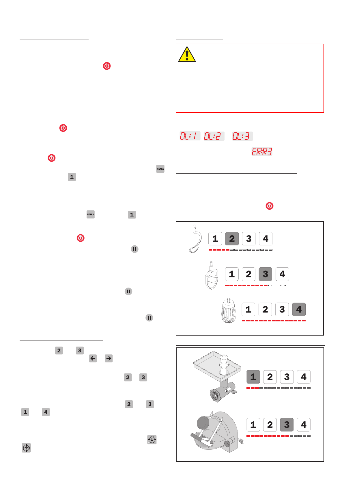
attaChment drive:
Themachinemaybettedwithanattachmentdriveinto
which optional accessories, such as meat mincers and
vegetable cutters, can be attached.
For further information on the assembly and use of optio-
nal accessories, please refer to the manual that comes
with the accessory.
The machine must be shut down when the ac-
cessoryisttedtotheattachmentdrive.
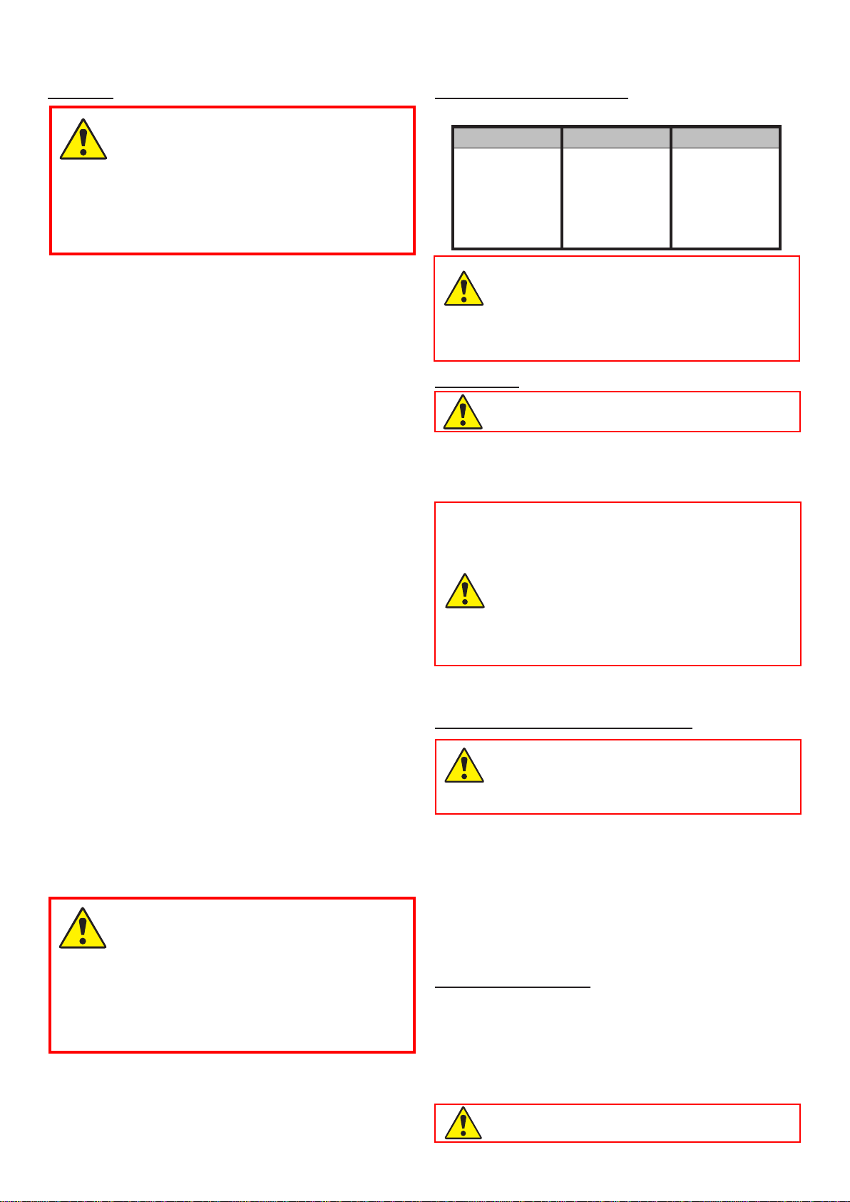
Whip Beater Hook
Cream Cake mix Bread dough
Egg whites Buttercream Rye bread
Mayonnaise Wafemix etc.
etc. Forcemeat
etc.

7
vl2 Control panel - sUrvey of varioUs operatinG sitUations:
The following pictures show various operating situations and corresponding explanation:
The mixer is connected to power and is ready for start -
ashingofthegreendiodeat will show that!
It is possible to set a start speed by pushing one of the
xedspeedsor , before is pushed.
When is pushed, the mixer will start in minimum speed.
Operating time is stated by pushing or .
A program is run byrstpushing and thereafter the
wanted number, e.g for program No. 1.
Emergency stop is activated - there is no light in the
display. If the red diode at isashing,themixerhas
stopped because the safety circuit has been interrupted,
either because the bowl arms have been lowered or the
safety guard has been opened.
The mixer is running and a speed has been chosen -
four diodes on the speed indicator are alight.
The speed can be changed by pushing one of the buttons
forthefourxedspeedsor or .
The mixer can be stopped without reset of the timer, by
pushing or by opening the safety guard. The mixer is
restarted by pushing .
has been pushed - yellow diode at isashing.The
mixer is started by pushing . The timer will start again
and the speed is running up to the chosen speed. If is
pushed, the timer is reset and the mixer will not start, but is
ready for start - green diode at willash(see picture 2).

8
Start/Stop
Pause
REMIX-function
Emergency stop
Time up
Text eld (timer)
Time down
Fixed speeds
Speed indicator
Speed down
Speed up
operation of the mixer:
Before starting the mixer:
• Put the desired tool into the bowl
• Place the bowl in the bowl arms
• Turnthetooltolockitintothebayonettting.
• Attach the safety guard
• Raise the bowl to its working position by means of the
handle for bowl lift.
• The mixer is ready for start
Start the mixer:
Push to start the mixer.
Push to increase the speed.
Push to reduce the speed.
Or push , , or to choose one of the xed
speeds.
Thespeedindicatorbelowtheelds to shows the
mixing speed of the tool.
Four xed speeds:
Forquickchoiceofspeed,usetheelds to .
Field corresponds lowest speed, aprox. 98 RPM.
Field corresponds aprox. 172 RPM.
Field corresponds aprox. 267 RPM.
Field corresponds maximum speed, aprox. 365 RPM.
Itispossibletochangethexedspeeds-seethepara-
graph „Change of xed speeds“.
Indication of operation time:
Before starting the mixer, an operation time for the mixer can
be chosen by pushing or . The operating time will
beshowninminutesandsecondsinthetimereldbetween
and .
The maximum operating time is 60 minutes.
Inspection of the ingredients during operation:
Ifitis wished to stop themixerwithoutreducingoperation time
and speed, push . The mixer will reduce speed and then
stop, the operation time will also stop.
It is now possible to lower the bowl to check the ingredients.
Raise the bowl and push , and the mixer will start and will
increase the speed to the speed chosen before pushing .
The operating time will also be continued.
Ifthe bowl is lowered while themixerisstopped, the operating
time is reset, and must be pushed to restart the mixer.
Stop the machine:
To stop the machine:
• Press . Running time will be reset.
• Press . Running time will not be reset.
• Pressthe emergency stop - therunningtimewill be reset.
• Remove the safety guard - the running time will be reset.
• Lower the bowl - the running time will be reset.
In all cases the mixer can be restarted by pressing .
It will start at the lowest speed.

9
the remix fUnCtion:
The special Remix-function is a shortcut to programming of
recipes.Whilethemixerisoperated,allcommandsarestored,
andwhenarecipeisnishedand is pushed, it is possible
to store the entire recipe under a program number.
• Therearefourprogramnumbers.
• Aprogramcannotbedeleted,butcanbereplaced.
• Theprogramsarenotdeletedincaseofnopower.
How to store a program:
• Firstpush .
• Runtheentirerecipeincludingpausesandchangesof
speed.
• Push .
• StoretheprogramasprogramNo.1bypushingrst
and then also continuously, until the total length of
theprogramisshowninthetimereld.Thetimereld
willthereafterash„P1“ three times.
How to run a program:
•First a short push on and then on . Now „P1“
appearsinthetimereldandimmediatelythereafterthe
total length of the program will be shown. The program
is run by pushing .
• Ifthespeedorthetimeischanged,or is pushed
when running a program, the program will be left and
the mixer must be run manually.
• Itispossibletoremovethesafetyguardwhilerunning
a program. When the safety guard is reattached, the
program can be resumed by pushing .
• Iftheprogramiscontainingapause,themixerwillstop
andat the same timeanacousticsignal is heard. When
the operator wants to restart the mixer, push and
the program will be resumed.
ChanGe of fixed speeds:
Fortheelds and it is possible to change the speed
for future mixing jobs. Push or to adjust the speed up
or down.
If required to store the adjusted speed, push or until two
beepsareheardandthediodesofthespeedindicatorareash-
ing. The adjusted speed has now been stored in the memory.
To return to the factory settings for button and push
and simultaneously, until a beep is heard.
reset of timer:
The timer can be reset by simultaneously pushing and
. If the timer is reset while the mixer is running, the mixer
will stop. Recommended max. speeds for attachment drive.
overloadinG:
The mixer must not be overloaded.
Possible overload situations:
• Working with excessively tough and heavy dough
• Mixer tool exceeding the recommended speed
• Wrong mixer tool being used.
Larger lumps of fat or chilled ingredients must be
reduced before they are placed in the bowl.
Prolonged overloading will cause the frequency converter
to stop the machine.
, or willbedisplayedin the timer
eld;thespeedwillnotbereduced,butthemixerwillstop
and the display will change to . Follow the descrip-
tion under Procedure in case of overloading.
proCedUre in Case of overloadinG:
Remove the cause of the overloading, e.g. empty the bowl.
• Push emergency stop
• Releaseemergencystop.
• Startthemixerbypushing .
reCommended max. speeds:
reCommended max. speeds for attaChment drive:
Recommended max. speeds (fac tory setting).

10
vl-2 Control, error Codes and possible solUtions:
Error codes and possible solutions:
The VL2 control will in case of certain errors show an error code in the display:
Too high temperature in the frequency converter.
Solution: Switch off the mixer and let it cool down.
Wrong voltage of power supply.
Solution: Compare the voltage indicated on the machine label with the power supply.
The motor has been constantly overloaded for a long period of time. The load has been between 100 - 150% of
maximumload.Theoverloadistypicallyfoundincaseofmixing/whippingtaskswithconstantload.
Solution: Switch off the mixer and reduce the quantity of ingredients in the bowl. Finish the work in a lower speed.
Low voltage is periodically noted in the power supply.
Solution: The machine’s power supply must be inspected by a technician.
Too high temperature in motor.
Solution: Switch off the mixer and let it cool down. Reduce the quantity of ingredients in the bowl. Finish the work in a lower
speed.
Communication break. Cable Connection between the control panel and frequency converter is defective.
Solution: Make sure the cable is seated properly in the connectors, replace the cable if it is defective.
, and The mixer has been overloaded from work with heavy dough or the like
Solution: Reduce the quantity of ingredients in the bowl. if possible, the product may be decomposed into smaller pieces
or diluted before the mixer is restarted. Finish the work in a lower speed.
Errors that do not cause an error code in the display:
The mixer does not start when is pushed, but the timer is counting as normal. There is no error code in the display.
Solution: The frequency converter is defective and must be exchanged. See “Service Instructions” page 10 for access
to the frequency converter.
The mixer does not start when is pushed. There is no error code in the display.
Solution: Activateemergencystopandreleaseitagain.Nowtwodifferentcodesshouldbeshowninthedisplay.Therst
codeisasmallsquareintopoftherstcipherofthedisplayfollowedbyaversioncode,thisisthesoftwarever-
sionofthecontrolpanel.Thenextcodeisasmallsquareinbottomoftherstcipherofthedisplayfollowedby
aversioncode,thisisthesoftwareversionofthefrequencyconverter.Ifnocodesareshownorifonlytherst
code is shown, the error can derive from either a defective communication cable between the control panel and
the frequency converter, or a defective frequency converter.
The mixer is totally “dead”, no light in the control panel.
Solution: Checkthe connection to power supply,ifconnectionandpowersupply
are OK, the error is either a defective communication cable between
the control panel and the frequency converter, or a defective fuse in
the frequency converter. See “Service Instructions” page 10 for
access to the frequency converter.

11
test proGrams:
To enter the test mode of the mixer, do as follows:
Raise the bowl and close the safety guard, push emergency stop.
Hold and and release the emergency stop at the same time. Now go through four test programs:
Test program 1: Test of elds.
Press to activate test program no. 1
OBS.Theeldsmustbeactivatedinthefollowingorder:
Brieypushthefollowingelds – – – – – – – – – – .
The mixer will now automatically run the next three test programs.
Test program 2: Test of light diodes.
Press to activate test program no. 2
Fortherst20secondsthecipher2willashinthedisplay-theremixmemorywillbeerased.Thenthelight
diodes in the speed indicator will light up one by one, while the other light diodes of the control panel are on.
Test program 3: Test of current measurement circuit in the frequency converter.
Press to activate test program no. 3
The motor starts and runs for approx. 20 seconds. After the 20 seconds a text is shown in the display, this text
will vary and can only be used for testing the function.
Test program 4: Test of micro switches in safety circuit.
Press to activate test program no. 4
OBS. It is important that the order is kept.
The cipher 1 is shown in the display until the safety guard is opened.
• Open and close the safety guard. The display shall now change to 2. If the display does not change to 2, the
micro switch at the safety guard is defective.
• Raise and lower the bowl again. The display shall now show 3. If the display does not change to 3, the micro
switch at the bowl lift is defective.
• Conclude the test by pushing emergency stop and release it again. The display shall now show version codes
for control panel and frequency converter resp., as earlier mentioned under “VL2 control, error codes and
possible solutions, error .
When running the testprogrammes, no specic order is required. It is possible to run the programmes individually

12
16
7
8
20
20
2
3
5
18
12
22 23
10
27
19 21
17
14
13
11
115
6
9
4
20
Before a possible repair or adjustment, the power must be switched off by
dismantling the connection cable from the power supply.
serviCe instrUCtions:
Cable bundle
stuck to motor
base with strips.
Cable bundle

13
16 15
24
25
23 21
26
27
22
19
The legs of the mixer are taken off by removing the screws (20).
2 1
The frequency converter is taken out in the following way:
a) Remove the lid of the mixer (1).
b) Cut the strips holding the cable bundle to the motor base
(13).
c) Remove the screw (22) in the bottom of the mixer.
d) Thefrequencyconverterincludingthemountingplate(23)
cannowbetilted/liftedoutofthebottomofthemixer.
e) Dismantle all plugs for the frequency converter.
f) The cover box (24) above the frequency converter (21)
can be removed by loosening the screws (25).
26 Thefuseisexchangedbytakingoutthefrequencyconverter
includingmountingplate(23)andthenremovingthecover
box (24).
27 The bottom plate is taken off by removing the legs of the
mixer (19), and the 2 nuts (28).
1
The lid of the mixer shall be removed and the plastic cover (2) shall be loosened by removing the 2 screws (3).
4 The control panelisremovedbyrstremovingtheplasticring(7)andthengerscrewontheattachmentdrive,
and then loosening the 2 screws (5).
6 The attachment driveistakenoutbyremovingthengerscrewandremovingtheplasticring(7), the control panel
(4) and the 4 bolts (8).
9 The display print is removed by removing the 2 screws (10).
1 1 The toothed belt is exchanged in the following way:
a) Remove the lid of the mixer (1) and the plastic cover (2).
b) Loosen the four nuts (12) holding the motor base (13). By pushing the base towards the front of the mixer, the
belt is slackened and can be lifted off the motor pulley (14) and the planetary head pulley (15).
c) The new toothed belt is mounted by pushing it downwards over the two pulleys.
d) The toothed belt is tightened by pushing the motor base towards the back of the mixer. Use a big screwdriver
or the like to hold the base in its place, while the nuts are mounted and tightened.
14 + 15 The pulleys are taken off in the following way:
a) Remove the lid of the mixer (1), the plastic cover (2)
and the toothed belt (11).
b) Screw the pointed screws (16) out of the pulley. The
pulley can now be lifted off the locking ring.
c) The locking rings are loosened from the shafts by
screwingoneofthepointedscrewsapprox.oneturn
down in the middle centre hole. The locking ring can
be removed.
17 The motor can be taken out in the following way:
a) The power must be switched off, or the connecting cable dismantled from the power supply.
b) Take off the lid of the mixer (1), the plastic cover (2), the toothed belt (11) and the motor pulley (14).
d) Remove the four nuts (12) and cut the strip holding the cable bundle on the back of the motor base. The mo-
tor base (13) with motor (17) can now be lifted out above the mixer.
e) Motor base and motor can be separated by removing the four screws (18).

14
31
33
35
34
32
29
1
6
4
11
30
29 The planetary head is taken off in the following way:
a) Take off the lid of the mixer (1), control panel (4), attachment drive (6), and toothed belt (11).
b) Take out the screws (30)
c) The plastic ring (31) can be taken off by hitting it slightly against the front edge and thereafter pressing a screw-
driver in between the plastic ring and the metal plate at the top of the plastic ring.
d) Take off the rubber packing (32).
e) The stainless steel head cap (33) can now be taken off by hitting the front edge slightly with a plastic hammer,
turning the planetary head 1800, and hitting again slightly on the front edge.
f) If only the bottom part of the planetary head is to be repaired, follow the instructions from c) to e). Hereafter the
planetary head can be disassembled by taking out the 3 bolts (34).
g) By loosening and removing the 4 bolts (35) the planetary head can be lowered.
Mounting of the planetary head to be in reverse order.

15
35
41
37
38 39 40
36
39 Micro switch for safety guard can be exchanged in the following way:
a) Remove the lid of the mixer (1) and the operating panel (7).
b) Screw out the pointed screw (37), and the cam disc (38) can be removed.
c) Thettingwithmicroswitch (39) can now be remo-
ved, and the micro can be exchanged by removing
thescrews(40). It might be necessary toloosen the
screws (41) beforethettingcanbetakenout.
d) The new micro switch is to be screwed on to the
tting,andthettingtobeplacedinthemachine.It
is important that the two screws (41) are adjusted
sothatthettingishorizontal.
35 Exchange the switch for bowl detection (with bracket) in the following way:
a) Take off the lid of the mixer (1) and the plastic cover (2).
b) Remove the base for motor (13) with the motor (17).
c) The bracket with the bowl detector switch (35) can be taken out by loose-
ning the two bolts (36) and removing the two red wires. Location of the
jumper must not be changed.
d) The new bracket with new switch is mounted in the mixer.
e) Thewiresmustbettedontheswitchsothatthetwomiddlelegsareempty.

16
RN20-194.39M RN20-194.19M RN20-194.29M
RN20-194.25M RN20-194.15M
RN20-194.26M RN20-194.16M
RN20-194.27M
RN20-194.17M
RN20-194.37M
RN20-194.28M
RN20-194.38M
CablinG diaGram:

17
eleCtriCal diaGrammes:
Side
Forrige side:
Næste side:
Antal siderialt:
Sidst udskrevet:
Sidst rettet:
Siderev.:
Projektrev.:
Godk. (dato/init):
Konstr. (projekt/side):
Tegningsnr.:
Sagsnr.:Projekttitel:
Kunde:
Sidetitel:
Filnavn:
Sideref.:
DCC: Målestok:
RN20, 20L, VL2 styring 5
2210-10-2016
Diagram
PC|SCHEMATIC Automation
30.020-08.01.01 10-10-20164
6
01
CE / CE
1:1
1 2 3 4 5 6 7 8
Black
Blue
Brown
Yellow/green
White
Yellow
Green
Black
Blue
Red
Front panel
Frequency inverter
Brown
Brown
Brown
Brown
Red
Orange
Orange
Red
Black
Blue
Blue
Black
Orange
Orange
Red
Red
Safety guard
CE/Bowl switch
Emergency
stop
Black
Blue
Blue
Black
Black
Blue
Blue
Black
Orange
Orange
White
Yellow
Green
Black
Blue
Red
White
Yellow
Green
Black
Blue
Red
VL-2 front panel
Black
Blue
Brown
Yellow/green
Motor
Emergency
stop
Power supply
Frame
1 x 200 -240V AC +N + PE
Power supply
Fuse in female Plug
Max. 16A
White
Black
Red
Yellow/Green
Brown
Blue
Main
Power
Cable

18
Indhold af Overensstemmelseserklæring, (Maskindirektivet, 2006/42/EC, Bilag II, del A) DK
Contents of the Declaration of conformity for machinery, (Machinery Directive 2006/42/EC, Annex II., sub. A) EN
Inhalt der Konformitätserklärung für Maschinen, (Richtlinie 2006/42/EG, Anhang II, sub A) DE
Contenu de la Déclaration de conformité d’une machine, (Directive Machine 2006/42/CE, Annexe II.A) FR
Inhoud van de verklaring van overeenstemming voor machines, (Richtlijn 2006/42/EC, Bijlage II, onder A) NL
Contenido de la declaración de conformidad sobre máquinas, (Directiva 2006/42/EC, Anexo II, sub A) ES
Fabrikant; Manufacturer; Hersteller; Fabricant; Fabrikant; Fabricante: A/S Wodschow & Co.
………………………………………………………………….……
Adresse; Address; Adresse; Adresse; Adres; Dirección: Kirkebjerg Søpark 6, DK-2605 Brøndby, Denmark
……………………………………………………………………….
Navn og adresse på den person, som er bemyndiget til at udarbejde teknisk dossier
Name and address of the person authorised to compile the technical file
Name und Anschrift der Person, die bevollmächtigt ist, die technischen Unterlagen zusammenzustellen
Nom et adresse de la personne autorisée à constituer le dossier technique
naam en adres van degene die gemachtigd is het technisch dossier samen te stellen
nombre y dirección de la persona facultada para elaborar el expediente técnico
Navn; Name; Name; Nom; Naam; Nombre: Kim Jensen
……………………………………………………………………….
Adresse; Address; Adresse; Adresse; Adres; Dirección: Kirkebjerg Søpark 6, DK-2605 Brøndby, Denmark
.........................................................................
Sted, dato; Place, date; Ort, Datum; Lieu, date ; Plaats, datum ; Place, Fecha: Brøndby, 21-09-2017
........................................................................
Erklærer hermed at denne røremaskine
Herewith we declare that this planetary mixer
Erklärt hiermit, dass diese Rührmaschine
Déclare que le batteur-mélangeur ci-dessous
Verklaart hiermede dat Menger
Declaramos que el producto batidora
•er i overensstemmelse med relevante bestemmelser i Maskindirektivet (Direktiv 2006/42/EC)
is in conformity with the relevant provisions of the Machinery Directive (2006/42/EC)
konform ist mit den Bestimmungen der EG-Maschinenrichtlinie (Direktiv 2006/42/EG)
Satisfait à l’ensemble des dispositions pertinentes de la Directive Machines (2006/42/CE)
voldoet aan de bepalingen van de Machinerichtlijn (Richtlijn 2006/42/EC)
corresponde a las exigencias básicas de la Directiva sobre Máquinas (Directiva 2006/42/EC)
•er i overensstemmelse med følgende andre CE-direktiver
is in conformity with the provisions of the following other EC-Directives
konform ist mit den Bestimmungen folgender weiterer EG-Richtlinien
Est conforme aux dispositions des Directives Européennes suivantes
voldoet aan de bepalingen van de volgende andere EG-richtlijnen
está en conformidad con las exigencias de las siguientes directivas de la CE
2014/30/EU ; 1935/2004 ; 10/2011 ; 2023/2006 ; RoHS 2011/65/EU , 822/2013 (DK only)
…………………………………………………………………………………………………………………………………………….....
Endvidere erklæres det
And furthermore, we declare that
Und dass
Et déclare par ailleurs que
En dat
Además declaramos que
•at de følgende (dele af) harmoniserede standarder, er blevet anvendt
the following (parts/clauses of) European harmonised standards have been used
folgende harmonisierte Normen (oder Teile/Klauseln hieraus) zur Anwendung gelangten
Les (parties/articles des) normes européennes harmonisées suivantes ont été utilisées
de volgende (onderdelen/bepalingen van) geharmoniseerde normen/nationale normen zijn toegepast
las siguientes normas armonizadas y normas nacionales (o partes de ellas) fueron aplicadas
EN454:2014 ; EN60204-1:2006; EN12100-2011
……………………………………………………………………………………………………………………………………...
EN61000-6-1:2007; EN61000-6-3:2007
……………………………………………………………………………………………………………………………………...
DS/EN 1672-2 + A1:2009
……………………………………………………………………………………………………………………………………...

19
Innehåll i örsäkran om maskinens överensstämmelse, (Maskindirektivet 2006/42/EG, bilaga 2, A) SV
Contenuto della dichiarazione di conformità per macchine, (Direttiva 2006/42/CE, Allegato II, parte A) IT
Sisukord masina vastavusdeklaratsioon , (Masinadirektiiv 2006/42/EÜ, lisa II, punkt A) ET
Treść Deklaracja zgodności dla maszyn (Dyrektywa maszynowa 2006/42/WE, Załącznik II, pkt A) PL
Sisältö vaatimustenmukaisuusvakuutus koneesta (Konedirektiivi 2006/42/EY, Liite II A) FI
Tillverkare; Fabbricante; Tootja; Producent; Valmistaja: A/S Wodschow & Co.
………………………………………………………………….……
Adress; Indirizzo; Aadress; Adres;Osoite: Kirkebjerg Søpark 6, DK-2605 Brøndby, Denmark
……………………………………………………………………….
Namn och adress till den person som är behörig att ställa samman den tekniska dokumentationen:
Nome e indirizzo della persona autorizzata a costituire il fascicolo tecnico
Tehnilise kausta volitatud koostaja nimi ja aadress
Imię i nazwisko oraz adres osoby upoważnionej do przygotowania dokumentacji technicznej
Henkilön nimi ja osoite, joka on valtuutettu kokoamaan teknisen tiedoston
Namn; Nome e cognome; Nimi; Imię i nazwisko;Nimi: Kim Jensen
……………………………………………………………………….
Adress; Indirizzo; Aadress; Adres; Osoite: Kirkebjerg Søpark 6, DK-2605 Brøndby, Denmark
.........................................................................
Ort och datum; Luogo e data; Koht, kuupäev; Miejscowość, data; Paikka, aika: Brøndby, 21-09-2017
........................................................................
Försäkrar härmed att denna blandningsmaskin
Con la presente si dichiara che questo mixer planetaria
Deklareerime käesolevaga, et Planetaarmikseri
Niniejszym oświadczamy, że mikser planetarny
vakuuttaa, että tämä mikseri tyyppi
•överensstämmer med tillämpliga bestämmelser i maskindirektivet (2006/42/EG)
is è conforme alle disposizioni della Direttiva Macchine (Direttiva 2006/42/CE)
vastab kehtivatele masinadirektiivi (2006/42/EÜ) nõuetele
spełnia wymagania odpowiednich przepisów dyrektywy maszynowej (2006/42/WE)
on konedirektiivin (2006/42/EY) asiaankuuluvien säännösten mukainen
•överensstämmer med bestämmelser i följande andra EG-direktiv
è conforme alle disposizioni delle seguenti altre direttive CE
vastab järgmiste EÜ direktiivide nõuetele
spełnia wymagania przepisów innych dyrektyw WE
on seuraavien muiden EY-direktiivien säännösten mukainen
2014/30/EU; 1935/2004 ; 10/2011 ; 2023/2006 ; RoHS 2011/65/EU ; 822/2013 (DK only)
…………………………………………………………………………………………………………………………………………………….…...
Vi försäkrar dessutom att
e che
Lisaks ülaltoodule deklareerime, et
Ponadto oświadczamy, że
ja lisäksi vakuuttaa, että
•följande (delar/paragrafer av) europeiska harmoniserade standarder har använts
sono state applicate le seguenti (parti/clausole di) norme armonizzate
kasutatud on järgmisi Euroopa harmoniseeritud standardeid (või nende osi/nõudeid)
zastosowano następujące części/klauzule zharmonizowanych norm europejskich
seuraavia eurooppalaisia yhdenmukaistettuja standardeja (tai niiden osia/kohtia) on sovellettu
EN454:2014 ; EN60204-1:2006; EN12100-2011
……………………………………………………………………………………………………………………………………..................
EN61000-6-1:2007; EN61000-6-3:2007
……………………………………………………………………………………………………………………………………...
DS/EN 1672-2 + A1:2009
……………………………………………………………………………………………………………………………………...

20
Table of contents
Other Metos Kitchen Appliance manuals

Metos
Metos DOGGER HD-WS User manual

Metos
Metos Start L 220 User manual

Metos
Metos 2025319 User manual

Metos
Metos CL-A1D User manual

Metos
Metos G250 User manual

Metos
Metos RG-100 User manual

Metos
Metos RG-400 User manual

Metos
Metos RG-250 Technical Document

Metos
Metos LM-32/P User manual

Metos
Metos pes 60 User manual

Metos
Metos MIXI MG22HD-1 User manual

Metos
Metos MF2 User manual

Metos
Metos MARVEL E1 User manual

Metos
Metos Prima 250 User manual

Metos
Metos DOMITOR User manual

Metos
Metos RG-200 User manual

Metos
Metos BETA BN 300 User manual

Metos
Metos LM-5/P User manual

Metos
Metos LM-10/P User manual

Metos
Metos MARVEL T User manual