manuals.online logo
Brands
  1. Home
  2. •
  3. Brands
  4. •
  5. Metra Electronics
  6. •
  7. Automobile Accessories
  8. •
  9. Metra Electronics 99-7400 User manual

Metra Electronics 99-7400 User manual

99-7400
INSTALLATION
INSTRUCTIONS
TOOLS REQUIRED
Cutting tool
Phillips screwdriver
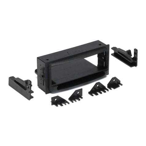
KIT COMPONENTS
Radio
Housing #1
Radio
Housing #2
Faceplate #1
Faceplate #2
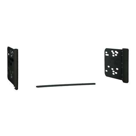
Bracket Set #9
Bracket
Set #17
Bracket Set #12
Bracket #13
& #14
Equalizer
Dummy Plate
Shaft
Masks
Mounting
Tabs #18 Mounting
Tabs #3
Mounting
Tabs #8
Mounting
Tabs #1
Mounting
Tabs #7
Mounting
Tabs #5
Mounting
Tabs #16
Mounting
Tabs #6
APPLICATIONS
CAR PAGE
NISSAN
200SX 1980-83.............................................................................1
200SX 1984-88.............................................................................2
240SX 1989-94.............................................................................3
Axxess 1989-90............................................................................ 4
Hardbody Pickup 1986.5-93..........................................................5
Maxima 1982-84.......................................................................... 6
Maxima 1987-88.......................................................................... 7
Maxima 1989-91.......................................................................... 8
Pathfinder 1987-93.......................................................................5
Pulsar 1983-86............................................................................. 9
Pulsar 1987-90............................................................................. 10
Sentra 1982-86.............................................................................9
Sentra 1987-90.............................................................................11
Stanza 1982-86.............................................................................12
Stanza 1987-89.............................................................................13
15
INST 7400
78
Locate the factory wiring harness in the
dash. Metra recommends using the
proper mating adaptor and making
connections as shown. (Isolate and
individually tape off the ends of any
unused wires to prevent electrical short
circuit).
Re-connect the battery terminal and test the unit
for proper operation. Mount the head unit/kit
assembly to the sub-dash with those screws
previously removed in step #1.
A
B
C
D
A) Strip wire ends back ½"
B) Twist ends together
C) Solder
D) Tape
IF AN EQUALIZER WILL BE INCLUDED: Slide the aftermarket equalizer into the back of the
kit. Using the hardware included with the equalizer, mount the unit to the kit. (see Fig. A)
IF AN EQUALIZER WILL NOT BE INCLUDED: Snap the Equalizer Dummy Plate into the
opening in the kit. (see Fig. B)
6
Fig. B
Fig. A
1-800-221-0932 www.metraonline.com
© COPYRIGHT 2001 METRA ELECTRONICS CORPORATION
rev. 201202
Disconnect the negative battery terminal to
prevent an accidental short circuit. Remove
(4) Phillips screws above the radio opening.
Remove (1) Phillips screw below the left side of
the radio opening. Remove (1) Phillips screw
from each side of the dash trim bezel. Pull off
the climate control knobs and remove the
climate control trim panel. Remove the
ashtray and lift the dash trim bezel off.
Remove (4) Phillips screws securing the
factory head unit and disconnect the wiring.
1
NISSAN 200SX 1980-83
2
3
Using the scored lines as a guide, cut and
remove the dashed portions of Faceplate
#2.
Slide Mounting Tabs #5 into slots "A" on Brackets #13 and #14.
The Mounting Tabs, Brackets and Bracket slots can be identified
by the stamped letter on each component. Skip to the Installation
Instructions for ALL VEHICLES on Page #14.
114
2-SHAFT HEAD UNITS: Snap the Faceplate onto the front of the Radio Housing. Slide the
aftermarket head unit into the kit and secure with shaft nuts. (see Fig. A)
DIN HEAD UNITS: Cut and remove the shaft supports from the Faceplate and Radio
Housing. Snap the Faceplate onto the front of the Housing. Slide the DIN cage into the kit and
secure by bending the metal locking tabs down. Slide the aftermarket head unit into the cage
until secure. (see Fig. B)
MAXIMA 1987-91, PULSAR 1987-90, STANZA1987-89, 240SX: Mount Bracket Set #9 to
Radio Housing #1 with (4) Phillips Pan-head Screws supplied. (see Fig. A)
SENTRA 1987-90: MountBracket Set #12 to Radio Housing #2 with (2) Phillips Pan-head
Screws supplied. (see Fig. B).
STANZA 1982-86, 200SX, HARDBODY PICKUP, PATHFINDER: Mount Bracket #13 and
#14 to Radio Housing #2 with (4) Phillips Pan-head Screws supplied. (see Fig. C)
MAXIMA 1982-84: Mount Bracket #14 to Radio Housing #2 with (2) Phillips Pan-head
Screws supplied. (see Fig. D)
ALL VEHICLES
5
4
Fig. B
Fig. B
Fig. C
Fig. A
"A"
"A"
Fig. A
Fig. D
13 2
3
Disconnect the negative battery terminal to
prevent an accidental short circuit. Remove
(1) #10 Phillips screw from each side of the
center console. Unsnap the coin tray and
remove (2) #10 Phillips screws exposed. Lift
the storage box carpet out and remove (2)
#10 Phillips screws exposed. Remove the
ashtray and (2) #8 Phillips screws exposed.
Remove the dash trim bezel. Remove (4)
screws securing the factory head unit and
disconnect the wiring.
1
NISSAN 200SX 1984-88
2
"B"
"B"
Locate Faceplate #2. (It is NOT necessary
to cut the Faceplate).
Slide Mounting Tabs #8 into slots "B" on Brackets #13 and #14.
The Mounting Tabs, Brackets and Bracket slots can be identified
by the stamped letter on each component. Skip to the Installation
Instructions for ALL VEHICLES on Page #14.
3
"B"
"B"
Disconnect the negative battery terminal to
prevent an accidental short circuit. Remove
the ashtray and (2) screws exposed at the
base of the dash trim bezel. Remove (2)
screws above the climate controls and
unclip the bezel. Remove (4) screws
securing the factory head unit and
disconnect the wiring.
1
NISSAN Stanza 1987-89
2
Using the scored lines as a guide, cut and
remove the dashed portions of Faceplate
#1.
Slide Mounting Tabs #8 into slots "B" on Bracket Set #9. The
Mounting Tabs, Bracket and Bracket slots can be identified by the
stamped letter on each component. Skip to the Installation
Instructions for ALL VEHICLES on Page #14.
312
Using the scored lines as a guide, cut and
remove the dashed portions of Faceplate
#1.
Disconnect the negative battery terminal to
prevent an accidental short circuit. Unclip
the dash trim bezel and remove. Remove
(4) Phillips screws securing the factory head
unit and disconnect the wiring.
1
NISSAN 240SX 1989-94
2
Align Bracket Set #17 with the lower mounting positions on Radio Housing #1, slide the
Brackets over the bottom shelf of the Housing and secure with (2) Phillips Pan-head Screws
supplied. (see Fig. A). Slide Mounting Tabs #18 into slots "C" on Bracket Set #9. (see Fig.
B). The Mounting Tabs, Brackets and Bracket slots can be identified by the stamped letter on
each component. Skip to the Installation Instructions for ALL VEHICLES on Page #14.
3
Fig. A
"C"
Fig. B
Disconnect the negative battery terminal to
prevent an accidental short circuit. Remove
(3) screws from the top of the dash trim
bezel. Remove (1) screw from each side of
the ashtray housing. Remove (3) screws
from the factory dummy plate. (The factory
pocket will remain intact).
1
NISSAN Stanza 1982-86
2
Using the scored lines as a guide, cut and
remove the dashed portions of
Faceplate #2.
3
"C"
"D"
Slide Mounting Tab #1 into slot "D" on Bracket #14. Slide
Mounting Tabs #8 into slots "C" on Bracket #13. The Mounting
Tabs, Brackets and Bracket slots can be identified by the stamped
letter on each component. Skip to the Installation Instructions for
ALL VEHICLES on Page #14.
11 4
Disconnect the negative battery terminal to
prevent an accidental short circuit. Remove (2)
screws from the top of the dash trim bezel and
remove the bezel. Remove (4) fasteners from
the factory head unit and disconnect the wiring.
1
NISSAN Axxess 1989-90
2
Using the scored lines as a guide, cut
and remove the dashed portions of
Faceplate #1.
3
Locate Radio Housing #2 and use the attached mounting tabs
during the installation in step #8. (It is NOT necessary to mount
Brackets to the Housing). Skip to the Installation Instructions for
ALL VEHICLES on Page #14.
Locate Faceplate #2. (It is NOT necessary
to cut the Faceplate).
Disconnect the negative battery terminal to
prevent an accidental short circuit. Remove
the ashtray. Remove (2) screws above the
climate controls. Remove (2) screws from
the base of the dash trim bezel and remove
the bezel. Remove the screws securing the
factory head unit and disconnect the wiring.
1
NISSAN Sentra 1987-90
2
3
Slide Mounting Tabs #8 into slots "E" onBracket Set #12. The
Mounting Tabs, Bracket and Bracket slots can be identified by the
stamped letter on each component. Skip to the Installation
Instructions for ALL VEHICLES on Page #14.
"E"
"E"
510
Using the scored lines as a guide, cut and
remove the dashed portions of Faceplate
#2.
Disconnect the negative battery terminal to
prevent an accidental short circuit. Remove
the ashtray and (1) screw exposed in the
top-right corner. Remove (2) Phillips screws
above the climate controls. Remove (2)
Phillips screws from the bottom of the dash
trim bezel. Unsnap the bezel and
disconnect the cigarette lighter wiring.
Remove (4) screws securing the factory
head unit and disconnect the wiring.
1
NISSAN Hardbody Pickup / Pathfinder 1986 1/2-93
2
3
Slide Mounting Tabs #8 into slots "E" on Brackets #13 and #14.
The Mounting Tabs, Brackets and Bracket slots can be identified
by the stamped letter on each component. Skip to the Installation
Instructions for ALL VEHICLES on Page #14.
"E"
"E"
3
Disconnect the negative battery terminal to
prevent an accidental short circuit. Remove
(3) screws above the climate controls.
Remove (2) screws from the bottom edge of
the dash trim bezel. Unclip the bezel and
remove. Remove (4) screws securing the
factory head unit and disconnect the wiring.
1
NISSAN Pulsar 1987-90
2
Slide Mounting Tabs #8 into slots "A" on Bracket Set #9. The
Mounting Tabs, Brackets and Bracket slots can be identified by the
stamped letter on each component. Skip to the Installation
Instructions for ALL VEHICLES on Page #14.
"A"
"A"
Using the scored lines as a guide, cut and
remove the dashed portions of Faceplate
#1.
96
Using the scored lines as a guide, cut and
remove the dashed portions of
Faceplate #2.
Disconnect the negative battery terminal to
prevent an accidental short circuit. Remove
the knobs from the climate controls. Using a
small screwdriver, pry out on the climate
control trim panel and remove. Remove (2)
screws securing the factory dummy plate
and discard the plate.
1
NISSAN Maxima 1982-84
2
3
Slide Mounting Tabs #8 into slots "C" onBracket Set #14. The
Mounting Tabs, Bracket and Bracket slots can be identified by the
stamped letter on each component. Skip to the Installation
Instructions for ALL VEHICLES on Page #14.
"C"
Using the scored lines as a guide, cut
and remove the dashed portions of
Faceplate #2. (This model does NOT
require the use of a Radio Housing or
Mounting Brackets).
Disconnect the negative battery terminal to
prevent an accidental short circuit. Remove (2)
Phillips screws from the top of the dash trim
bezel. Remove the ashtray and (1) screw
exposed on the ashtray bracket. Remove the
bracket. Unclip the dash trim bezel and
disconnect the wiring. Remove (2) Phillips
screws securing the factory head unit to the shelf.
Remove the unit and disconnect the wiring.
1
NISSAN Pulsar 1983-86 / Sentra 1982-86
2
3
2-SHAFT HEAD UNITS: Slide the aftermarket head unit into the dash trim bezel, place the
Faceplate and Shaft Masks over the radio shafts and secure with shaft nuts. (see Fig. A).
Make wiring connections and re-attach the dash trim bezel.
DIN HEAD UNITS: Cut and remove the shaft supports from the Faceplate. Cut a DIN opening
in the dash trim bezel. Slide the DIN cage through the Faceplate into the dash trim bezel and
secure by bending the metal locking tabs down. Make wiring connections and slide the
aftermarket head unit into the cage until secure. (see Fig. B). Re-attach the dash trim bezel.
Fig. B
Fig. A
78
3
Disconnect the negative battery terminal to
prevent an accidental short circuit. Remove
(2) Phillips screws from the bottom of the
dash trim bezel. Remove (2) Phillips screws
above the radio opening. Unclip the dash
trim bezel and disconnect the defroster and
rear wiper wiring. Remove (4) screws
securing the factory head unit and
disconnect the wiring.
1
NISSAN Maxima 1987-88
2
"E"
"E"
Slide Mounting Tabs #18 into slots "E" onBracket Set #9. The
Mounting Tabs, Bracket and Bracket slots can be identified by the
stamped letter on each component. Skip to the Installation
Instructions for ALL VEHICLES on Page #14.
Using the scored lines as a guide, cut and
remove the dashed portions of Faceplate
#1.
3
Disconnect the negative battery terminal to
prevent an accidental short circuit. Remove
(2) Phillips screws above the radio opening.
Remove the ashtray and (1) screw in the
right corner of the ashtray housing. Remove
(1) screw below the cigarette lighter and
unclip the dash trim bezel. Remove (4)
screws securing the factory head unit and
disconnect the wiring.
1
NISSAN Maxima 1989-91
2
"D"
"D"
Using the scored lines as a guide, cut and
remove the dashed portions of
Faceplate #1.
Slide Mounting Tabs #18 into slots "D" on Brackets #9. The
Mounting Tabs, Brackets and Bracket slots can be identified by the
stamped letter on each component. Skip to the Installation
Instructions for ALL VEHICLES on Page #14.

Other Metra Electronics Automobile Accessories manuals
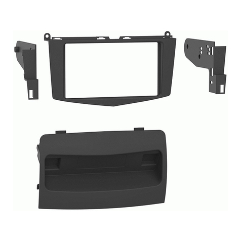
Metra Electronics 99-7308 User manual

Metra Electronics

Metra Electronics 99-7308 User manual

Metra Electronics 99-8220 User manual

Metra Electronics

Metra Electronics 99-8220 User manual

Metra Electronics iBeam TE-AHD7M User manual

Metra Electronics

Metra Electronics iBeam TE-AHD7M User manual

Metra Electronics LEXUS 99-8151 User manual

Metra Electronics

Metra Electronics LEXUS 99-8151 User manual

Metra Electronics 99-7860 User manual

Metra Electronics

Metra Electronics 99-7860 User manual

Metra Electronics 99-3103 User manual

Metra Electronics

Metra Electronics 99-3103 User manual

Metra Electronics INST-GMOS05 User manual

Metra Electronics

Metra Electronics INST-GMOS05 User manual

Metra Electronics 99-3307G User manual

Metra Electronics

Metra Electronics 99-3307G User manual

Metra Electronics 95-7863 User manual

Metra Electronics

Metra Electronics 95-7863 User manual

Metra Electronics 95-5817 User manual

Metra Electronics

Metra Electronics 95-5817 User manual
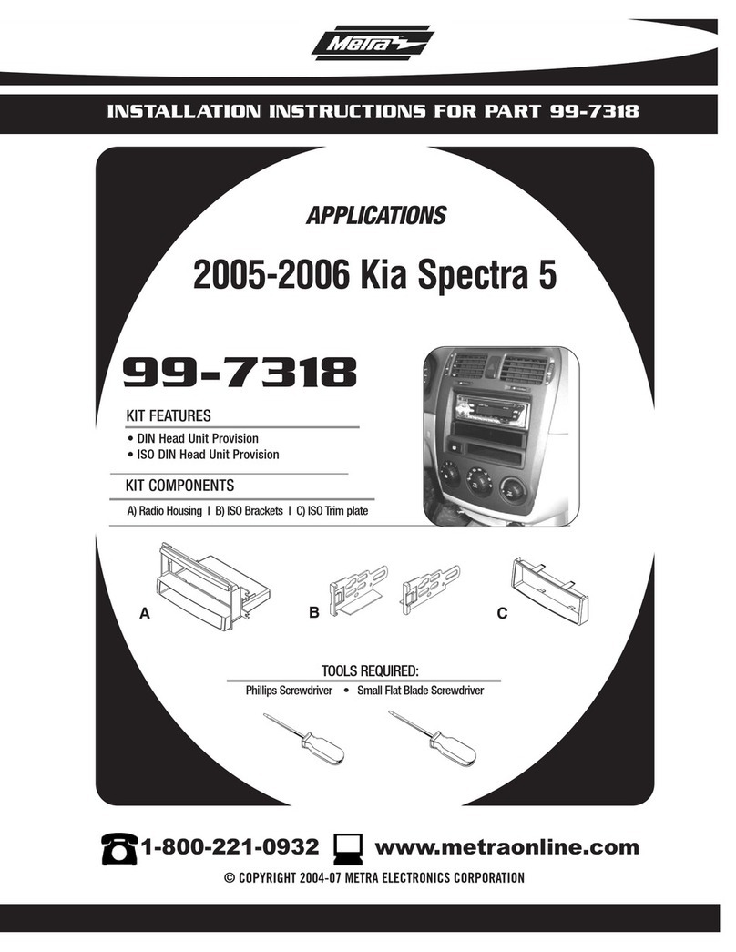
Metra Electronics 108-MI1 User manual

Metra Electronics

Metra Electronics 108-MI1 User manual

Metra Electronics 95-8210 User manual

Metra Electronics

Metra Electronics 95-8210 User manual

Metra Electronics 95-7332 User manual

Metra Electronics

Metra Electronics 95-7332 User manual

Metra Electronics 99-9009 User manual

Metra Electronics

Metra Electronics 99-9009 User manual

Metra Electronics 95-9313B User manual

Metra Electronics

Metra Electronics 95-9313B User manual

Metra Electronics 95-8166G User manual

Metra Electronics

Metra Electronics 95-8166G User manual

Metra Electronics 99-7861 User manual

Metra Electronics

Metra Electronics 99-7861 User manual

Metra Electronics 99-6520B User manual

Metra Electronics

Metra Electronics 99-6520B User manual

Metra Electronics 95-3009 User manual

Metra Electronics

Metra Electronics 95-3009 User manual

Metra Electronics 99-3305 User manual

Metra Electronics

Metra Electronics 99-3305 User manual

Metra Electronics 99-7503 User manual

Metra Electronics

Metra Electronics 99-7503 User manual

Metra Electronics 99-8723B User manual

Metra Electronics

Metra Electronics 99-8723B User manual

Metra Electronics 99-8201 User manual

Metra Electronics

Metra Electronics 99-8201 User manual

Metra Electronics 99-5721 User manual

Metra Electronics

Metra Electronics 99-5721 User manual
Popular Automobile Accessories manuals by other brands

Magneti Marelli AC161 Installation instruction

Magneti Marelli

Magneti Marelli AC161 Installation instruction

FDI uEZ GUI Start here

FDI

FDI uEZ GUI Start here

JCROffroad JT Install instructions

JCROffroad

JCROffroad JT Install instructions

Rostra VOXXElectronics 250-1930 owner's guide

Rostra

Rostra VOXXElectronics 250-1930 owner's guide

TOP VEHICLE TECH GR3FORD5 installation manual

TOP VEHICLE TECH

TOP VEHICLE TECH GR3FORD5 installation manual

Safe Fleet PRIME DESIGN AR-2000-BLK manual

Safe Fleet

Safe Fleet PRIME DESIGN AR-2000-BLK manual

Skoda Fabia Combi 5J Fitting instructions

Skoda

Skoda Fabia Combi 5J Fitting instructions

Camcar 40077 Al Mounting instructions

Camcar

Camcar 40077 Al Mounting instructions

Camcar 40089 AL Mounting instructions

Camcar

Camcar 40089 AL Mounting instructions

Impac Tradesman 2000 installation manual

Impac

Impac Tradesman 2000 installation manual

DVB OFFROAD BRSB-01 installation manual

DVB

DVB OFFROAD BRSB-01 installation manual

Safari Snorkel SS385HF installation guide

Safari Snorkel

Safari Snorkel SS385HF installation guide

ULTIMATE SPEED 279746 Assembly and Safety Advice

ULTIMATE SPEED

ULTIMATE SPEED 279746 Assembly and Safety Advice

SSV Works DF-F65 manual

SSV Works

SSV Works DF-F65 manual

ULTIMATE SPEED CARBON Assembly and Safety Advice

ULTIMATE SPEED

ULTIMATE SPEED CARBON Assembly and Safety Advice

Witter F174 Fitting instructions

Witter

Witter F174 Fitting instructions

WeatherTech No-Drill installation instructions

WeatherTech

WeatherTech No-Drill installation instructions

TAUBENREUTHER 1-336050 Installation instruction

TAUBENREUTHER

TAUBENREUTHER 1-336050 Installation instruction

manuals.online logo
manuals.online logoBrands
  • About & Mission
  • Contact us
  • Privacy Policy
  • Terms and Conditions

Copyright 2025 Manuals.Online. All Rights Reserved.