1. GENERAL
This instruction manual contains important information
regarding the installation, operation and trouble shooting
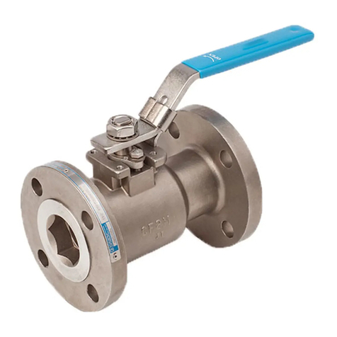
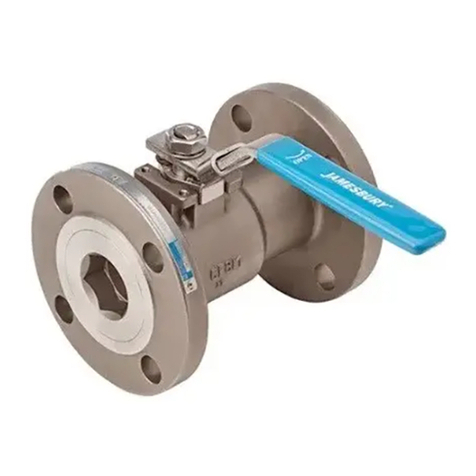
of the Jamesbury® 3” & 4”(DN 80 & 100) Series 5000 Flanged
Ball Valves. Please read these instructions carefully and save
them for further reference.
1.1 WARNING
FOR YOUR SAFETY AND PROTECTION, IT IS IMPORTANT THAT THE
FOLLOWING PRECAUTIONS BE TAKEN PRIOR TO REMOVING THE
VALVE FROM SERVICE OR BEFORE ANY DISASSEMBLY OF THE VALVE.
1. AT ALL TIMES DURING THIS ENTIRE PROCEDURE, KEEP HANDS
OUT OF THE VALVE,A REMOTELY ACTUATED VALVE COULD
CLOSE AT ANY TIME AND RESULT IN SERIOUS INJURY.
2. KNOW WHAT MEDIA IS IN THE LINE. IF THERE IS ANY DOUBT,
CHECK WITH THE PROPER AUTHORITY.
3. WEAR ANY PROTECTIVE CLOTHING OR EQUIPMENT NORMALLY
REQUIRED WHEN WORKING WITH THE MEDIA INVOLVED.
4. DEPRESSURIZE THE LINE AND VALVE AS FOLLOWS:
A. OPEN THE VALVE AND DRAIN THE LINE.
B. CLOSE AND OPEN THE VALVE TO RELIEVE ANY RESIDUAL
PRESSURE THAT MAY BE IN THE VALVE PRIOR TO REMOVING
THE VALVE FROM SERVICE. LEAVE THE VALVE IN THE OPEN
POSITION.
C. AFTER REMOVAL AND PRIOR TO ANY DISASSEMBLY, DRAIN
ANY REMAINING MEDIA BY PLACING THE VALVE IN THE
VERTICAL POSITION AND CAREFULLY OPEN AND CLOSE
THE VALVE SEVERAL TIMES.
5. SEAT AND BODY RATINGS THE PRACTICAL AND SAFE USE OF
THIS PRODUCT IS DETERMINED BY BOTH THE SEAT AND BODY
RATINGS. READ THE NAME TAG AND CHECK BOTH RATINGS.
THIS PRODUCT IS AVAILABLE WITH A VARIETY OF SEAT
MATERIALS. SOME OF THE SEAT MATERIALS HAVE PRESSURE
RATINGS THAT ARE LESS THAN THE BODY RATINGS. ALL OF
THE BODY AND SEAT RATINGS ARE DEPENDENT ON VALVE
TYPE AND SIZE, SEAT MATERIAL, BOLTING MATERIAL, AND
TEMPERATURE. DO NOT EXCEED THESE RATINGS.
2. INSTALLATION
1. Place the valve in the open position.
2. Flow through a Jamesbury valve can be in either
direction. However, it is recommended that the valve
be installed with the insert facing upstream. For dead
ended service 3” and 4” (DN 80 & 100) Series 5000
valves must be installed with the insert upstream.
3. Flow through this Jamesbury valve can be in either
direction. It is recommended, however, that the valve
be installed with the insert facing upstream.
IMPORTANT: The valve should be tightened between anges
using appropriate gaskets and fasteners for the service, in
compliance with applicable piping codes and standards.
4. If there is seepage past the packing upon installation,
the valve may have been subjected to wide
temperature variations in shipment. “Leak-tight”
performance will be restored by a packing adjustment
described in the MAINTENANCE Section.
3. MAINTENANCE
Although Metso’s Jamesbury valves are designed to work
under severe conditions, proper preventative maintenance
can signicantly help to prevent unplanned downtime and
in real terms reduce the total cost of ownership. Metso
recommends inspecting valves at least every ve (5) years.
The inspection and maintenance frequency depends on
the actual application and process condition.
1. Routine maintenance consists of tightening the
packing nut (15) periodically to compensate for stem
seal wear. This may be done as follows:
A. Manual Valves - Loosen the handle screw (18) and
tighten the packing nut (15) until snug, then tighten
an additional 1/4 turn. retighten the handle screw.
B. Actuated Valves - When the valve is connected to an
actuator by a no-play (clamped) type coupling, loosen
the coupling before tightening the packing nut.
2. Overhaul Maintenance consists of replacing seats
and seals. A standard repair kit consisting of these
parts may be obtained through your Metso Distributor
(See Table 1). Refer to the Disassembly and Assembly
sections below for details on installing the repair kits.
TABLE 1
Repair Kits
Valve Size 3” (DN 80)
5150, 530S, 5300
4” (DN 100)
5150
4” (DN 100)
530S, 5300
PTFE Seats RKN75TT RKN76TT RKN77TT
Filled PTFE Seats RKN75MT RKN76MT RKN77MT
PEEK® Seats RKN75LT RKN76LT RKN77LT
UHMW Seats RKN75UU RKN76UU RKN77UU
PFA Seats RKN75BT RKN76BT RKN77BT
PFA Seats &
Seals RKN75BP RKN76BP RKN77BP
Repair Kits contain one pair of seats, a body seal, upper stem seals, a lower stem
seal and maintenance instructions.
NOTE: Repair kits contain two #8 seals and one #24 seal set. Depending on valve
model, one #8 or one #24 will not be used. See note under parts list on page 4
3.1 Disassembly
Tools needed to disassemble Jamesbury valves, such as
the “breechlock eld wrench” mentioned in Step 5, may be
ordered as service parts from your local Metso Distributor.
NOTE: Replacement of seats and seals is recommended if
any disassembly becomes necessary.
1. Read the WARNING Section before performing any
work on the valve.
2. Open the valve.
3. Remove the cap screw (18) holding the handle to the stem.
4. Remove the handle (17).
5. The “breechlock” design requires that the insert be
compressed and rotated approximately 60 degrees
before removal. Use one of the following methods:
IMO 3/18
IMO-059 EN 3


