7 ND91P 70 en 5
2.4 Technical specifications
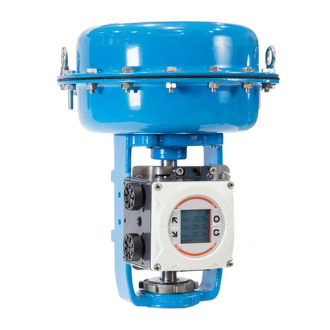
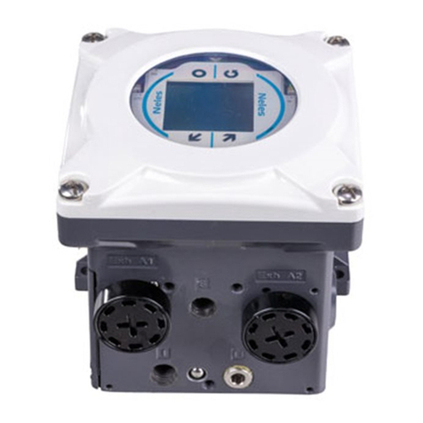
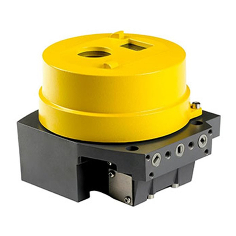
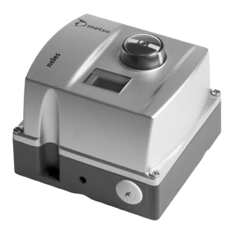
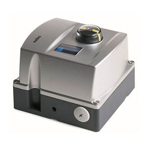
ND9100P INTELLIGENT VALVE CONTROLLER
General
Bus powered, no external power supply required.
Suitable for rotary and sliding-stem valves.
Actuator connections in accordance with VDI/VDE 3845
and IEC 60534-6 standards.
Flush mounting on NelesCV™ control valves.
Action: Double or single acting
Travel range: Linear; 10–120 mm with standard IEC parts.
Larger strokes possible with suitable kits
Rotary: 45–95°.
Measurement range 110° with freely
rotating feedback shaft.
Environmental influence
Standard temperature range:
-40° – +85 °C / -40° – +185 °F
Influence of temperature on valve position:
< 0.5 % / 10 °K
Influence of vibration on valve position:
< 1 % under 2g 5–150 Hz,
1g 150–300 Hz, 0.5g 300–2000 Hz
Enclosure
Material: Anodised aluminium alloy and
polymer composite
Protection class: IP66, NEMA 4X
Pneumatic ports: G 1/4
Electrical connection: max. 2.5 mm2
Cable gland thread: M20 x 1.5
Weight: 1.8 kg / 4.0 lbs
Mechanical and digital position indicator visible
through the main cover
Special corrosion resistant finish available
Pneumatics
Supply pressure: 1.4–8 bar / 20–115 psi
Effect of supply pressure on valve position:
<0.1 % at 10 % difference in inlet pressure
Air quality: According to ISO 8573-1:2001
Solid particles: Class 5
(3–5 µm filtration is recommended)
Humidity: Class 1
(dew point 10 °C/50 °F below minimum
temperature is recommended)
Oil class: 3 (or <1 ppm))
Capacity with 4 bar / 60 psi supply:
5.5 Nm3/h / 3.3 scfm (spool valve 2)
12 Nm3/h / 7.1 scfm (spool valve 3)
38 Nm3/h / 22.4 scfm (spool valve 6)
Consumption with 4 bar / 60 psi supply
in steady state position:
< 0.6 Nm3/h / 0.35 scfm (spool valves 2 & 3
< 1.0 Nm3/h / 0.6 scfm (spool valve 6)
Electronics
Power supply: taken from bus
Bus voltage: 9 to 32 V DC, reverse polarity protection
Max basic current:17.2 mA
Fault current (FDE):3.9 mA
EEx ia IIC T6: Ui ≤24 V
Ii ≤380 mA
Pi ≤5.32 W
Ci < 5 nF
Li < 10 µH
EEx nL IIC: Ui ≤32 V
Ii ≤380 mA
Pi ≤5.32 W
Ci < 5 nF
Li < 10 µH
(ATEX approval is valid under these conditions)
Performance with moderate constant-load,
actuators EC05-EC10
Values at 20 °C / 68 °F and without any additional instru-
ments, such as boosters or quick exhaust valves etc.
Dead band acc. to IEC 61514:
≤0.1 %
Hysteresis acc. to IEC 61514:
<0.5 %
Local user interface functions
❑Local control of the valve
❑Monitoring of valve position, input signal, temper-
ature, supply and actuator pressure difference
❑Guided start-up function
❑LUI may be locked remotely to prevent unauthor-
ised access
❑Calibration: Automatic / Manual
❑1-point calibration
❑Limit switch state monitoring
❑Control configuration: aggressive, fast, optimum,
stable, maximum stability
❑Mode selection: Automatic/Manual
❑Rotation: valve rotation clockwise or counter-
clockwise to close
❑Dead angle
❑Low cut-off, cut-off safety range (default 2 %)
❑Positioner fail action, open/close
❑Actuator type, double/single acting
❑Valve type, rotary/linear IEC/nelesCV Globe/FLI
❑Language selection: English, German and French
Approvals
Intrinsically safe and non incendive
ATEX EC-Directive 94/9/EC;
EN 50014
EN 50020: 2 G EEx ia IIC T4...T6
EN 50284: 1 G EEx ia IIC T4...T6
EN50021: 3 G EEx nA II T4...T6
IEC 60079-27: EEx nL IIC
EN 50281-1-1: D T90 °C
CSA CAN/CSA-C22.2-0,-142, -157;
CAN/CSA-E60079-0,-11, -15
IS Class I, Div. 1, Groups A, B, C, D T4...T6
IS Class I, Zone 0, Ex ia IIC T4...T6
NI Class I, Div. 2, Groups A, B, C, D T4...T6
FM FM Class 3600, 3610, 3611, 3810:
IS Class I, Div. 1, Groups A, B, C, D T4...T6
IS Class I, Zone 0, AEx ia IIC T4...T6
NI Class I, Div. 2, Groups A, B, C, D T4...T6
NI Class I, Zone 2, Ex nA II T4...T6


