3 MOUNTING THE ACTUATOR
First verify that the output torque of the actuator is appro-
priate for the torque requirements of the valve and that
the actuator duty cycle is appropriate for the intended
application.
3.1 Actuator Drive Output Requirements:
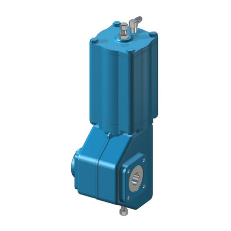
Valvcon's LCR-Series actuators have a square output drive.
ISO 5211 bolt circle configurations are provided (see
Figures 2A and 2B).
3.2 Bracket Requirements:
It is mandatory that the actuator be firmly secured to a
sturdy mounting bracket. A minimum of four bolts with
lockwashers must be used to secure the actuator to the
bracket. There can be no flexibility in the bracket, and
backlash ("play") in the coupling should be minimized. In
addition, the actuator output shaft must be in line (cen-
tered) with the valve shaft. This avoids side-loading the
shafts (crossed-slot couplings are more tolerant of mis-
alignment).
4 MANUAL OVERRIDE
4.1 Male output:
To operate the actuator manually, push the override shaft
down approximately 1/4", and use a wrench on the flats of
the shaft to rotate the actuator. As noted in Figure 2A, the
coupling must be designed to accommodate this shaft
movement. The override shaft can also be used to provide
visual identification of the valve's position.
4.2 Female output:
To operate the actuator manually, push the override shaft
down approximately 1/4", and use a wrench on the flats of
the shaft to rotate the actuator.The override shaft can also
be used to provide visual identification of the valve's posi-
tion.
5 WIRING
Note: Be sure to follow local wiring codes.
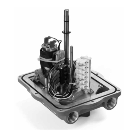
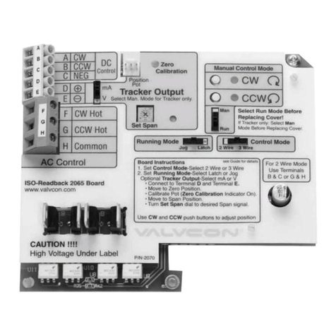
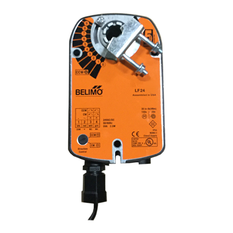
The identification label on each actuator specifies the volt-
age and current requirements for the actuator. Figure 3
shows the standard power and control wiring connections
for AC and DC actuators. To operate the LCR-Series actua-
tor, the user supplies power to the actuator's motor
through two limit switches. The limit switches control the
actuator's mechanical travel limits and are factory set at 90
degrees.
5.1 AC
To drive the actuator counterclockwise (CCW), apply
power to terminals 1 and 3. To drive the actuator clock-
wise (CW), apply power to terminals 1 and 4. The actuator
can be driven fully open (CCW) or closed (CW) by main-
taining power to the motor until the actuator trips the
internal limit switches. Power can also be disconnected at
any point during the travel to position the actuator. (see
Figure 3A)
5.2 DC
DC voltage actuators require a reversing of the power
polarity. To drive the actuator CW, apply power so that ter-
minal 1 is negative and terminal 4 is positive. To drive the
actuator CCW, apply power so that terminal 1 is positive
and terminal 3 is negative. (see Figure 3B)
NOTE: LCR series actuators have a 25% duty cycle,
which means that for every operating cycle that the
actuator is ON (to open or close the valve), the actuator
must be OFF for a time equal to three operating cycles.
For example, if the operating cycle time is 5 seconds,
for every operating cycle that the actuator is ON, it
must be OFF for 15 seconds. Exceeding the actuator's
duty cycle may cause the thermal overload switch to
temporarily shut off power to the motor.
6IMO-I1262
