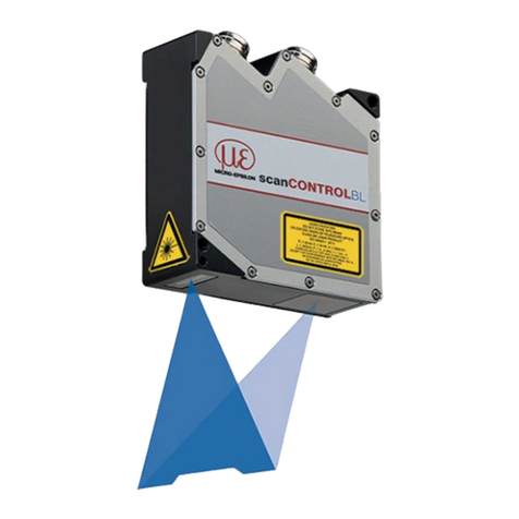
optoCONTROL CLS1000
Inhalt
1. Safety ........................................................................................................................................ 5
1.1 Symbols Used ................................................................................................................................................. 5
1.2 Warnings.......................................................................................................................................................... 5
1.3 Notes on CE Marking ...................................................................................................................................... 5
1.4 Intended Use ................................................................................................................................................... 6
1.5 Proper Environment......................................................................................................................................... 6
2. Functional Principle, Technical Data ....................................................................................... 7
2.1 Short Description............................................................................................................................................. 7
2.2 Measuring Principle ........................................................................................................................................ 7
2.2.1 Transmission Mode ........................................................................................................................ 7
2.2.2 Reflex Mode (One-Way System) .................................................................................................... 8
2.2.3 Reflex Mode (Two-Way System)..................................................................................................... 8
2.3 Technical Data ................................................................................................................................................. 9
2.3.1 CLS1000-AU ................................................................................................................................... 9
2.3.2 CLS1000-AI................................................................................................................................... 10
2.3.3 CLS1000-QN................................................................................................................................. 11
2.3.4 CLS1000-2QN............................................................................................................................... 12
2.3.5 CLS1000-OC................................................................................................................................. 13
3. Delivery .................................................................................................................................. 14
3.1 Unpacking/Included in Delivery .................................................................................................................... 14
3.2 Storage .......................................................................................................................................................... 14
4. Installation and Assembly...................................................................................................... 15
4.1 Installation and Mounting .............................................................................................................................. 15
4.2 Installation of the Sensor ............................................................................................................................... 16
4.3 Installation on a DIN Rail ............................................................................................................................... 17
4.4 Control and Display Elements....................................................................................................................... 18
4.5 Electrical Connections Controller.................................................................................................................. 19
4.5.1 General Pin Assignment............................................................................................................... 19
4.5.2 Supply Voltage ............................................................................................................................ 19
4.5.3 Model CLS1000-AU...................................................................................................................... 20
4.5.3.1 Pin Assignment ......................................................................................................... 20
4.5.3.2 Analog Output........................................................................................................... 20
4.5.3.3 Switching Output ...................................................................................................... 20
4.5.3.4 Trigger Input CLS1000-AU-xx-T ................................................................................ 21
4.5.4 Model CLS1000-AI........................................................................................................................ 22
4.5.4.1 Pin Assignment ......................................................................................................... 22
4.5.4.2 Analog Output........................................................................................................... 22
4.5.4.3 Switching Output ...................................................................................................... 22
4.5.4.4 Trigger Input CLS1000-AI-xx-T.................................................................................. 23
4.5.5 Model CLS1000-QN ..................................................................................................................... 24
4.5.5.1 Pin Assignment ......................................................................................................... 24
4.5.5.2 Switching Outputs .................................................................................................... 24
4.5.5.3 Trigger Input CLS1000-QN-xx-T................................................................................ 25
4.5.6 Model CLS1000-2Q ...................................................................................................................... 26
4.5.6.1 Pin Assignment ......................................................................................................... 26
4.5.6.2 Switching Outputs..................................................................................................... 26
4.5.6.3 Trigger Input CLS1000-2Q-xx-T ................................................................................ 27
4.5.7 Model CLS1000-OC ..................................................................................................................... 28
4.5.7.1 Pin Assignment ......................................................................................................... 28
4.5.7.2 Switching Outputs..................................................................................................... 28
4.5.7.3 Trigger Input CLS1000-OC-xx-T................................................................................ 29
5. Operation ................................................................................................................................ 30
5.1 Initial Operation ............................................................................................................................................. 30
5.2 Membrane Keys............................................................................................................................................. 30
5.3 Overview of Operating Menu......................................................................................................................... 31
5.4 Operating Menu............................................................................................................................................. 32
5.4.1 Legend of the Menu Structure ..................................................................................................... 32
5.4.2 Start .............................................................................................................................................. 32
5.4.3 T / Teach-in ................................................................................................................................... 33
5.4.3.1 ST/ Standard Teach-in .............................................................................................. 34
5.4.3.2 HST / HighSensitive Teach-in ................................................................................... 34
5.4.3.3 LST / LowSensitive Teach-in..................................................................................... 35
5.4.3.4 DT / Dark Teach-in / Background Teach-in............................................................... 35
5.4.3.5 OBT / OptimalBright Teach-in................................................................................... 35
5.4.3.6 ODT / OptimalDark Teach-in..................................................................................... 36
5.4.3.7 PPT / PeakToPeak Teach-in ...................................................................................... 36
5.4.3.8 2PT / 2Point Teach-in ................................................................................................ 36
5.4.3.9 MST / ManualSensitive Teach-in............................................................................... 36
5.4.4 Q1 / Config Q1.............................................................................................................................. 37
5.4.4.1 OPM / Switching Polarity .......................................................................................... 37
5.4.4.2 TIME / Timer ............................................................................................................. 37
5.4.4.3 Q2 / Config Q2 .......................................................................................................... 37
