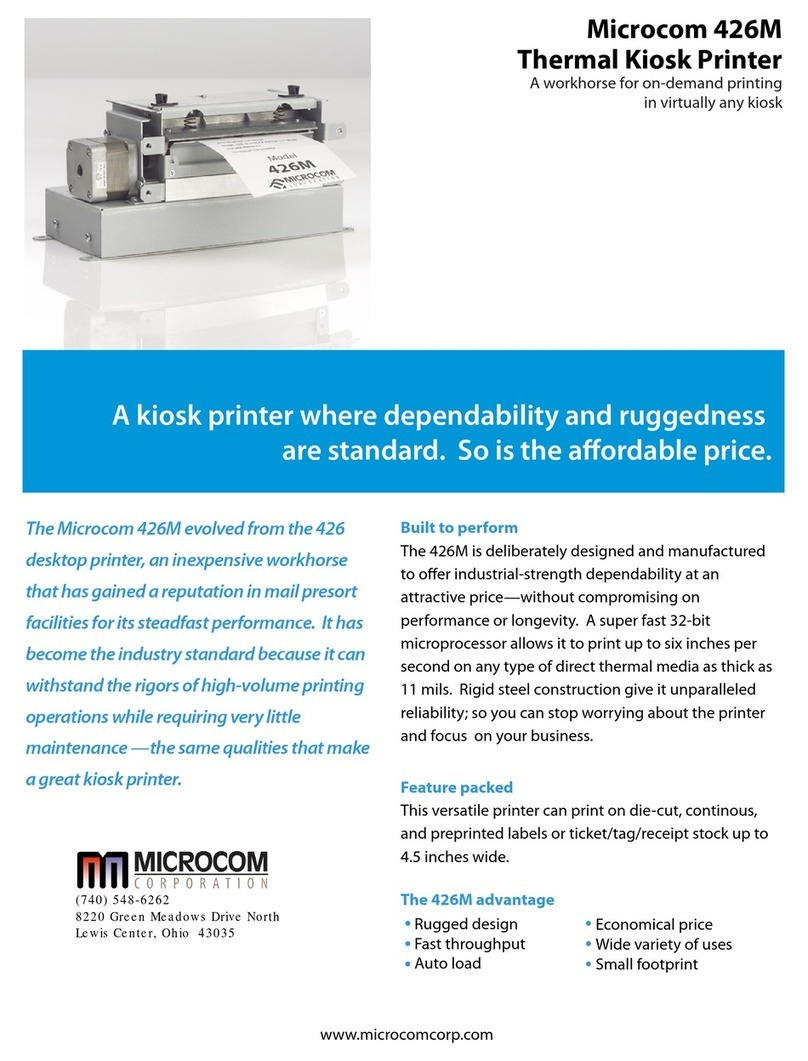
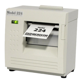
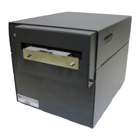
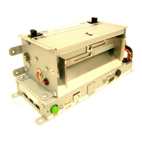
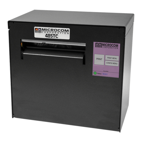
Microcom LDS2 Owner's manual

LDS2
PROGRAMMING MANUAL
PART NUMBER 880019-0202
Revised: September 7, 2021 CPC
Copyright © 2021 by Microcom Corporation, Lewis Center, Ohio – All rights reserved.


Proprietary Statement
This manual contains information proprietary to Microcom Corporation. This information
intended solely for the use of parties operating and maintaining such equipment described
herein.
Product Enhancements
Microcom Corporation is committed to the continual improvement of performance and
quality in our products. For this reason, specifications are subject to change without notice.
Documentation support written up to code version 1.11.44.
Liability Disclaimer
Microcom Corporation makes every effort to assure that all information and specifications
contained in this manual are accurate; however, mistakes are sometimes made. Microcom
Corporation shall not be liable for any damages resulting in the use or misuse of this
product. The exclusion or limitation involving consequential or incidental damage does not
apply to all states; therefore, limitation mentioned above may or may not apply.
FCC Compliance Statement
This equipment has been tested and found to comply with the limits for a Class A digital
device, pursuant to Part 15 of the FCC rules. These limits are designed to provide
reasonable protection against harmful interference when the equipment is operated in a
commercial environment. This equipment generates, uses, and can radiate radio frequency
energy, and if not installed and used in accordance with the instructions contained in this
manual, may cause harmful interference to radio communications.
HyperTerminal®and HyperAccess®are trademarks of Hilgraeve Inc.
Centronics® is a registered trademark of Data Computer Corporation.
HP®and LaserJet II®are trademarks of Hewlett-Packard Company.
Arial®is a registered trademark of The Monotype Corporation.
TrueType®is a registered trademark of Apple Computer, Inc.
Microsoft®, Windows®, Windows NT®are registered trademarks of Microsoft Corporation.
Other products and company names mentioned herein may be trademarks of their
respective owners.


LDS2 Programming Manual - 880019-0202i
Table of Contents
LIST OF FIGURES...............................................................................................................VI
LIST OF TABLES..............................................................................................................VIII
INTRODUCTION...................................................................................................................X
CHAPTER 1:...................................................................................................DESIGNING USING LDS2
........................................................................................................................................... 1-1
1.1 Special Control Codes..................................................................................................1-1
1.2 Script Creation: An Overview ......................................................................................1-2
1.3 Begin Script - ^A)filename...........................................................................................1-4
1.4 Script Header ................................................................................................................1-4
1.4.1 LSX (Label Width) LSX, LSY, GAP, DRM, SPD, DET, OFX, OFY, AGD ............................... 1-5
1.4.2 LSY (Label Height) LSX, LSY, GAP, DRM, SPD, DET, OFX, OFY, AGD............................... 1-5
1.4.3 GAP (Gap Size) LSX, LSY, GAP, DRM, SPD, DET, OFX, OFY, AGD...................................1-5
1.4.4 DRM (Distance to Registration Mark) LSX, LSY, GAP, DRM, SPD, DET, OFX, OFY, AGD...... 1-5
1.4.5 SPD (Print Speed) LSX, LSY, GAP, DRM, SPD, DET, OFX, OFY, AGD................................. 1-5
1.4.6 DET (Detection Method) LSX, LSY, GAP, DRM, SPD, DET, OFX, OFY, AGD......................... 1-6
1.4.7 OFX (Offset X Direction) LSX, LSY, GAP, DRM, SPD, DET, OFX, OFY, AGD......................... 1-6
1.4.8 OFY (Offset Y Direction) LSX, LSY, GAP, DRM, SPD, DET, OFX, OFY, AGD......................... 1-6
1.4.9 AGD (Activate Gap Detector) LSX, LSY, GAP, DRM, SPD, DET, OFX, OFY, AGD.................. 1-6
1.5 Format Entry Command - ^Fn) ....................................................................................1-6
1.5.1 XB (X Coordinate) XB, YB, CI, SW, SH, AI, DN, FO, FJ, FW, CS, FC, CC............................... 1-7
1.5.2 YB (Y Coordinate) XB, YB, CI, SW, SH, AI, DN, FO, FJ, FW, CS, FC, CC...............................1-7
1.5.3 CI (Conversion Identifier) XB, YB, CI, SW, SH, AI, DN, FO, FJ, FW, CS, FC, CC.................... 1-7
1.5.4 1.5.4 SW (Size Width) XB, YB, CI, SW, SH, AI, DN, FO, FJ, FW, CS, FC, CC...................... 1-10
1.5.5 SH (Size Height) XB, YB, CI, SW, SH, AI, DN, FO, FJ, FW, CS, FC, CC ...............................1-10
1.5.6 AI (Attribute Index) XB, YB, CI, SW, SH, AI, DN, FO, FJ, FW, CS, FC, CC...........................1-11
1.5.7 DN (Direction) XB, YB, CI, SW, SH, AI, DN, FO, FJ, FW, CS, FC, CC .................................1-12
1.5.8 FO (Field Orientation) XB, YB, CI, SW, SH, AI, DN, FO, FJ, FW, CS, FC, CC...................... 1-12
1.5.9 FJ (Field Justification) XB, YB, CI, SW, SH, AI, DN, FO, FJ, FW, CS, FC, CC.......................1-12
1.5.10 FW (Field Width) XB, YB, CI, SW, SH, AI, DN, FO, FJ, FW, CS, FC, CC..........................1-13
1.5.11 CS (Character Spacing) XB, YB, CI, SW, SH, AI, DN, FO, FJ, FW, CS, FC, CC ............... 1-13
1.5.12 FC (First Character) XB, YB, CI, SW, SH, AI, DN, FO, FJ, FW, CS, FC, CC..................... 1-13
1.5.13 CC (Character Count) XB, YB, CI, SW, SH, AI, DN, FO, FJ, FW, CS, FC, CC.................. 1-13
1.6 Text Entry Command - ^Tn).......................................................................................1-14
CHAPTER 2: PRINTER COMMANDS............................................................................ 2-2
2.1 Script Management Commands...................................................................................2-2
2.1.1 Begin Script - ^A)filename ........................................................................................................... 2-3
2.1.2 Begin Temporary Script - ^AT)filename ...................................................................................... 2-3
2.1.3 Format Entry Command - ^Fn)XB,YB,CI,SW,SH,AI,DN,FO,FJ,FW,CS,FC,CC ......................... 2-3
2.1.4 Text Entry Command - ^Tn)text data........................................................................................... 2-3
2.2 2xx Series Commands..................................................................................................2-4
2.2.1 ^D200) LSX, LSY, GAP, DRM, SPD, DET, OFX, OFY, AGD (Script Header)............................ 2-4
2.2.2 ^D202)n (Text Replacement Header)........................................................................................ 2-4
2.2.3 ^D203)LSX,LSY,GAP,DRM,SPD,DET,OFX,OFY,AGD,BT,FS ................................................... 2-5
(Direct Image Script Header).................................................................................................................... 2-5
2.3 3xx Series Commands..................................................................................................2-5
2.3.1 ^D300)n (Print Command)......................................................................................................... 2-6
2.3.2 ^D305)1 (Infinity Print Command) ............................................................................................. 2-6
2.3.3 ^D311)1 (Top-OF-Form)............................................................................................................ 2-6
2.3.4 ^D312)n (Form Feed) ................................................................................................................ 2-6

ii LDS2 Programming Manual - 880019-0202
2.3.5 ^D313)n1,n2 (Advance Media) ...................................................................................................2-6
2.3.6 ^D323)n (List Enablements) .....................................................................................................2-6
2.3.7 ^D324)n (List Statistics).............................................................................................................2-6
2.3.8 ^D325)n (List Selections)...........................................................................................................2-7
2.3.9 ^D326)n (List Settings) ............................................................................................................2-7
2.3.10 ^D327)1 (List Status).............................................................................................................2-7
2.3.11 ^D339)size (Load Firmware) ..................................................................................................2-7
2.3.12 ^D340)filename (Load/Save File)...........................................................................................2-7
2.3.13 ^D341)type (List Catalog).....................................................................................................2-8
2.3.14 ^D342)filename (Delete File)..................................................................................................2-8
2.3.15 ^D343)filename (List Script) ...................................................................................................2-8
2.3.16 ^D345)filename (Load Volatile File) .......................................................................................2-8
2.3.17 ^D350)filename (Execute Script)............................................................................................2-9
2.3.18 ^D360)1 (List Memory Available) ..........................................................................................2-9
2.3.19 ^D365)? (List Status Response List)....................................................................................2-9
2.3.20 ^D390)1 (Reset Printer).......................................................................................................2-10
2.3.21 ^D391)1 (Restore Configuration Defaults) ..........................................................................2-10
2.3.22 ^D392)1 (Restore Property Defaults) ..................................................................................2-11
2.4 5xx Series Commands................................................................................................2-11
2.4.1 ^D501)n (Select Emulation Mode)...........................................................................................2-11
2.4.2 ^D506)n (Select Cutter Type) ..................................................................................................2-11
2.4.3 ^D508)n (Select Label Present Detector Type).......................................................................2-12
2.4.4 ^D509)n (Select INPUT1 Response Polarity and Action)........................................................2-12
2.4.5 ^D511)n (Select INPUT2 Response Polarity and Action)........................................................2-12
2.4.6 ^D541)n (Select Button 1 Response) ......................................................................................2-12
2.4.7 ^D550)n (Select Printer Response Set)...................................................................................2-13
2.4.8 ^D564)n (Select Measurement Units)......................................................................................2-14
2.4.9 ^D565)n (Select Speed Units) .................................................................................................2-14
2.4.10 ^D566)n (Select Temperature Units)...................................................................................2-14
2.4.11 ^D567)filename (Select Power-up Script) ...........................................................................2-14
2.4.12 ^D570)n (Select Active Port)...............................................................................................2-15
2.4.13 ^D581)n (Select Stock Out Handling Method) ....................................................................2-15
2.4.14 ^D597)n (Select Dispense Mode)........................................................................................2-15
2.5 6xx Series Commands................................................................................................2-16
2.5.1 ^D629)n1,n2 (Set Takeup Pre and Post Timing).....................................................................2-16
2.5.2 ^D630)n1, n2 (Set Takeup Motor Reverse Timing).................................................................2-17
2.5.3 ^D631)n (Set Media Width)......................................................................................................2-17
2.5.4 ^D632)n (Set Media Height) ....................................................................................................2-17
2.5.5 ^D633)n (Set GAP Size)..........................................................................................................2-17
2.5.6 ^D634)n (Distance To Registration Mark) ...............................................................................2-17
2.5.7 ^D635)n (Set Print Speed).......................................................................................................2-18
2.5.8 ^D636)n (Set Detection Mode) ...............................................................................................2-18
2.5.8.1 Detection Mode - None (0)................................................................................................2-18
2.5.8.2 Detection Mode - Blackline (1)..........................................................................................2-19
2.5.8.3 Detection Mode - Die-cut (2) and Blow-hole (3)................................................................2-19
2.5.9 ^D637)n (Offset X Direction)....................................................................................................2-20
2.5.10 ^D638)n (Offset Y Direction) ...............................................................................................2-20
2.5.11 ^D639)n (Set Centering Offset)...........................................................................................2-20
2.5.12 ^D640)n (Set Delay Time Between Labels) ........................................................................2-20
2.5.13 ^D641)n (Set Retraction Delay Time)..................................................................................2-20
2.5.14 ^D642)n (Set Advance/Retract Distance)............................................................................2-20
2.5.15 ^D643)n (Set Print Head to LPD Distance) ........................................................................2-21
2.5.16 ^D644)n (Set Idle Recognition Delay)................................................................................2-21
2.5.17 ^D645)n1 (Set Advance/Retract Speed) ............................................................................2-21
2.5.18 ^D646)n (Set Platen Roller Compensation) .......................................................................2-21
2.5.19 ^D647)dc,dp (Set Print Head Parameters)..........................................................................2-21
2.5.20 ^D648)n (Set Blackline Sensor to Print Head Distance) .....................................................2-22
2.5.21 ^D649)n (Set Gap Sensor to Print Head Distance).............................................................2-22
2.5.22 ^D650)n (Set AGD Value) ...................................................................................................2-22
2.5.23 ^D655)n (Set Labels Printed) ..............................................................................................2-22

LDS2 Programming Manual - 880019-0202iii
2.5.24 ^D670) (Set Serial Port) ....................................................................................................2-22
2.5.25 ^D673)n (Set DHCP)...........................................................................................................2-23
2.5.26 ^D674)n (Set Ethernet Port Number).................................................................................. 2-23
2.5.27 ^D675)n (Set Printer IP Address)........................................................................................2-23
2.5.28 ^D677)n (Set Gateway IP Address) ....................................................................................2-23
2.5.29 ^D679)n (Set Net Mask Address)........................................................................................2-23
2.5.30 ^D680)n (Set Gap Threshold) .............................................................................................2-23
2.5.31 ^D681)n (Set Blackline Threshold)......................................................................................2-24
2.5.32 ^D682)n (Set Stock Sensor Threshold)...............................................................................2-24
2.5.33 ^D690)n (Set Darkness Range) ..........................................................................................2-24
2.6 7xx Series Commands................................................................................................2-24
2.6.1 ^D720)n (Enable Auto Power-Up Script).................................................................................2-24
2.6.2 ^D721)n (Enable Auto Enquiry After Print)..............................................................................2-25
2.6.3 ^D723)n1,n2 (Enable Auto TOF on Power up and Autoload).................................................2-25
2.6.4 ^D726)n (Enable Auto ACK/NAK) ...........................................................................................2-25
2.6.5 ^D727)n (Enable Auto Error Reporting) ..................................................................................2-25
2.6.6 ^D729)n (Enable Takeup Motor Control).................................................................................2-25
2.6.7 ^D740)n (Enable Cutter)..........................................................................................................2-26
2.7 9xx Series Commands................................................................................................2-26
2.7.1 ^D900)d, s (Diagnostic Tic-Tic Mode) .....................................................................................2-26
2.7.1.1 Blackline Threshold Calculation Example.........................................................................2-27
2.7.1.2 Die-Cut/Blowhole Threshold Calculation Example........................................................... 2-29
2.7.2 ^D930)level (Get Access Code Key) .......................................................................................2-32
2.7.3 ^D931)level, password (Change Access Level)....................................................................... 2-32
2.7.4 ^D932) (List Access Passwords)............................................................................................2-32
2.7.5 ^D945)n (List Diagnostic Dump)..............................................................................................2-32
2.7.6 ^D960)n (Print Test Pattern)....................................................................................................2-33
2.7.7 ^D971)n (Edit Inches Printed Statistic)....................................................................................2-33
2.7.8 ^D972)n (Edit Total Inches Run Statistic)................................................................................2-33
2.7.9 ^D973)n (Edit Power on Time Statistic)...................................................................................2-33
2.7.10 ^D974)n (Edit Head Up Cycles Statistic) ............................................................................2-33
2.7.11 ^D975)n (Clear All Statistics) ..............................................................................................2-33
2.7.12 ^D976)n (Edit Unit Serial Number)......................................................................................2-33
2.7.13 ^D977)n (Edit Cutter Cycles Statistic).................................................................................2-34
2.7.14 ^D978)0xn (Edit Ethernet MAC Address) ........................................................................... 2-34
2.7.15 ^D979)n (Edit CPU Serial Number).....................................................................................2-34
2.7.16 ^D980)n (Calibrate Sensors)...............................................................................................2-34
CHAPTER 3: SPECIAL FEATURES .............................................................................. 3-1
3.1 Reverse Video...............................................................................................................3-1
3.2 Line Draw ......................................................................................................................3-2
CHAPTER 4: BAR CODES............................................................................................. 4-1
4.1 Generating Bar Codes..................................................................................................4-1
4.1.1 CI Parameter ...............................................................................................................................4-1
4.1.2 SW Parameter .............................................................................................................................4-1
4.1.3 SH Parameter..............................................................................................................................4-1
4.1.4 AI Parameter................................................................................................................................ 4-1
4.2 Linear Bar Codes..........................................................................................................4-1
4.2.1 Codabar (Rationalized)................................................................................................................ 4-2
4.2.2 Code 128 (Manual Compression)................................................................................................4-2
4.2.3 Code 128 (Automatic Compression) ........................................................................................... 4-3
4.2.4 Code 39 ....................................................................................................................................... 4-3
4.2.5 Code 93 ....................................................................................................................................... 4-4
4.2.6 Code I2of5 (Interleaved 2 of 5).................................................................................................... 4-4
4.2.7 MSI0 (Modified Plessey).............................................................................................................. 4-4
4.2.8 MSI1 (Modified Plessey).............................................................................................................. 4-4
4.2.9 MSI2 (Modified Plessey).............................................................................................................. 4-4

iv LDS2 Programming Manual - 880019-0202
4.2.10 Postnet.....................................................................................................................................4-4
4.3 2D Bar Codes.................................................................................................................4-5
4.3.1 Data Matrix...................................................................................................................................4-5
4.3.2 PDF-417.......................................................................................................................................4-9
4.3.3 Aztec..........................................................................................................................................4-11
4.3.4 QR Code....................................................................................................................................4-14
CHAPTER 5 : DIAGNOSTICS AND TROUBLESHOOTING ........................................5-1
5.1 Diagnostic Mode............................................................................................................5-1
5.1.1 Entering Diagnostic Mode............................................................................................................5-1
5.1.2 Status Label.................................................................................................................................5-1
5.1.3 Listing Commands.......................................................................................................................5-2
5.2 Enquiry Responses.......................................................................................................5-5
5.2.1 Fatal Error Responses.................................................................................................................5-7
5.2.1.1 >STOCK OUT< (01)............................................................................................................5-8
5.2.1.2 >STOCK OVERADVANCED< (02).....................................................................................5-8
5.2.1.3 >STOCK JAMMED< (03)....................................................................................................5-8
5.2.1.4 >CUTTER JAMMED< (10)..................................................................................................5-8
5.2.1.5 >MISSING LABEL< (1C).....................................................................................................5-8
5.2.1.6 >INCOMPLETE FORM< (1D).............................................................................................5-8
5.2.1.7 >SCRIPT ERROR< (30) .....................................................................................................5-9
5.2.1.8 >INVALID PARAMETER< (31)...........................................................................................5-9
5.3 Basic Status Responses...............................................................................................5-9
5.3.1 >OK< (06) ....................................................................................................................................5-9
5.3.2 >PM< (14)....................................................................................................................................5-9
5.3.3 >INPUT 1< (21)............................................................................................................................5-9
5.3.4 >INPUT 2< (22)............................................................................................................................5-9
5.3.5 >RESTARTED< (80)..................................................................................................................5-10
5.3.6 >READY< (81)...........................................................................................................................5-10
5.3.7 >PAUSED< (83).........................................................................................................................5-10
5.3.8 >LABEL/TAG PRESENT< (86)..................................................................................................5-10
5.3.9 >STOCK ADVANCED< (87)......................................................................................................5-10
5.3.10 >STOCK NOT LOADED< (8F)..............................................................................................5-10
5.3.11 >RETRACTION DELAY< (90)...............................................................................................5-10
5.3.12 >PRINT DELAY< (91) ...........................................................................................................5-10
5.3.13 >FLASH MEMORY LOW< (B0).............................................................................................5-11
5.3.14 >BUTTON 1 TAPPED< (C0).................................................................................................5-11
5.3.15 >BUTTON 1 HELD< (C1)......................................................................................................5-11
5.3.16 >TEMPERATURE OUT OF RANGE< (D0)...........................................................................5-11
5.3.17 >NONEXISTENT COMMAND< (D1).....................................................................................5-11
5.3.18 >ZIP FILE ERROR< (D3)......................................................................................................5-11
5.3.19 >FILE CONVERSION ERROR< (D4) ...................................................................................5-11
5.3.20 >UNSUPPORTED FILE TYPE< (D5)....................................................................................5-11
5.3.21 >FILE NOT FOUND< (D6) ....................................................................................................5-12
5.3.22 >INADEQUATE ACCESS MODE< (D7) ...............................................................................5-12
5.3.23 >INADEQUATE FLASH SPACE< (DA).................................................................................5-12
5.3.24 >FILE TOO LARGE< (F2).....................................................................................................5-12
5.3.25 >POWERED DOWN< (FF)....................................................................................................5-12
APPENDIX ........................................................................................................................6-1
Appendix A: Limited Warranty............................................................................................6-1
Appendix B: RMA Procedure..............................................................................................6-3
Appendix C: ^D Command Summary.................................................................................6-5
Glossary..................................................................................................................................6-15

LDS2 Programming Manual - 880019-0202v

vi LDS2 Programming Manual - 880019-0202
List of Figures
Figure 1 Sample Script Format.......................................................................... 1-3
Figure 2 Script Parameters................................................................................ 1-4
Figure 3 Distance-to-Registration Mark (DRM)..................................................1-5
Figure 4 Format Entry Command......................................................................1-7
Figure 5 Text Entry Command......................................................................... 1-14
Figure 6 Detection Mode - None...................................................................... 2-18
Figure 7 Detection Mode - Blackline................................................................ 2-19
Figure 8 Detection Mode - Die-cut and Blowhole ............................................ 2-20
Figure 9 ^D900 Blackline Listing...................................................................... 2-28
Figure 10 ^D900 Blackline Threshold Example................................................. 2-29
Figure 11 ^D900 Die-cut Listing......................................................................... 2-30
Figure 12 ^D900 Die-cut Threshold Example.................................................... 2-31
Figure 13 Reverse Video..................................................................................... 3-1
Figure 14 Line Draw Reverse Video....................................................................3-2
Figure 15 Line Draw Feature............................................................................... 3-2
Figure 16 Two Lines............................................................................................ 3-3
Figure 17 Box Creation........................................................................................ 3-4
Figure 18 Code 128 Subset Switching ................................................................4-2
Figure 19 Data Matrix Format Structure .............................................................. 4-5
Figure 20 PDF-417 Format Structure................................................................ 4-10
Figure 21 Status Label Printout...........................................................................5-1
Figure 22 Display Calibration...............................................................................5-2
Figure 23 ^D323) - List Enablements Example ...................................................5-2
Figure 24 ^D326) - List Settings Example ...........................................................5-3
Figure 25 ^D325) - List Selections Example........................................................5-4
Figure 26 ^D324) - List Statistics Example..........................................................5-4
Figure 27 ^D960)1 or ^K Test Pattern ................................................................. 5-5

LDS2 Programming Manual - 880019-0202vii

viii LDS2 Programming Manual - 880019-0202
List of Tables
Table 1 Resident Bitmapped Fonts ..................................................................1-8
Table 2 Bar Code Index.................................................................................... 1-9
Table 3 Attribute Index ................................................................................... 1-11
Table 4 Field Justifications............................................................................. 1-12
Table 5 ^Dxxx Series Commands .................................................................... 2-2
Table 6 ^D365) Status Response List ............................................................ 2-10
Table 7 Print Head Parameters...................................................................... 2-22
Table 8 ^D670) Parameters ........................................................................... 2-23
Table 9 ^D900) and ^D902) Parameters ........................................................ 2-26
Table 10 Access Levels.................................................................................... 2-32
Table 11 Code 128 Special Function Access.....................................................4-2
Table 12Data Matrix Configuration Parameters ................................................ 4-6
Table 13 Data Matrix Encoding Schemes .......................................................... 4-7
Table 14 ASCII Codeword Values...................................................................... 4-8
Table 15 Data Matrix Special Characters...........................................................4-9
Table 16 PDF-417 Error Correction Level........................................................ 4-11
Table 17 Aztec Configuration Values............................................................... 4-13
Table 18 Aztec Encoding Modes...................................................................... 4-13
Table 19 Aztec Videos #................................................................................... 4-13
Table 20 Aztec ECC%...................................................................................... 4-14
Table 21 QR Code Configuration Parameters.................................................. 4-19
Table 22 QR Code Error Correction Level........................................................ 4-20
Table 23 Enquiry Responses ............................................................................. 5-7

LDS2 Programming Manual - 880019-0202ix

x LDS2 Programming Manual - 880019-0202
Introduction
This programming guide provides the user with an overview of the LDS2 command structure
and label formatting requirements found in the X85 Series printers.
The Label Design Software (LDS2) is the resident printer control language used to create,
store and print label scripts, while also controlling the other various printer features.
LDS2 may be used in conjunction with mini-computers, mainframes, personal computers,
and most other special purpose computers. The examples provided within this guide use
an IBM®compatible personal computer with an available communication port, Windows
Notepad, and MCT a terminal emulation program found on our website. The examples
included use Windows Notepad and then sent to the printer’s active communication port
using the MCT program.
This programming manual was written against the feature of code version 01.01.06.

LDS2 Programming Manual - 880019-0202xi

LDS2 Programming Manual – 880019-0202 1-1
Chapter 1: Designing Using LDS2
Label formats or scripts are very easy to design using LDS2 by following these basic steps below.
LDS2 printers require the use of hardware flow control (CTS/RTS) for proper data management to
occur. Do not use Software flow control to manage data sent to an LDS2 printer.
1. Determine the media type, media size, and print speed desired for your application; enter this
data into the script header.
2. Determine the type of handling operation desired and use the appropriate LDS2 printer control
commands.
3. Define the formatting instructions for the type and placement of data.
4. Enter the text data that corresponds to the formatting instructions.
5. Send the script to the printer.
1.1 Special Control Codes
The printer can accept either the one-character control code (“Ctrl + E”) or the two-character caret
(^) plus alpha character (“^E”). Control codes are processed immediately while the ^Dxx commands
are processed in the order they are issued. It is recognized that some mainframe and mini-
computers cannot use the ASCII carat “^” character. The ASCII pipe symbol “|” can be used as a
substitute for these instances. Below is a list of special control codes used by LDS2.
^A Begin Script: Marks the beginning of an LDS2 script file entry.
^C Clear Halting Error: When issued five consecutive times with a one second delay between
each ^C the printer will clear blocking or halting error conditions returning ^Dxx command
responsiveness. If the printer has remaining jobs in the queue, the printer will return to a
>PAUSED< state instead of the >READY< state. Please note that if the condition that
caused the error still exists, pressing the print button and/or sending further scripts will cause
this error to be reported again. Halting error messages are conditions that must be corrected
before printing may resume. Refer to section 6.3 for additional information regarding error
conditions.
^D Standard Command Preface: Combined with three-digit number issues a command. See
Chapter 2 for more information regarding ^D commands.
^E Printer Enquiry: Causes the printer to list its current status to an active communications
port.
^K Print Test Label: Causes the printer to print a test pattern consisting of diagonal lines used
to test the condition of the dots on the print head.
^L Form Feed: Scrolls one label out of the printer using the previous formats layout.
^M Carriage Return: Represents a Carriage Return (CR) character or 0x0D.
^O Top-of-Form (TOF): Instructs the printer to perform a TOF operation that uses the Label
Present Detector (LPD) in order to retract the media to the proper alignment in regards to the
print head.

Printer Specifications Chapter 1
1-2 LDS2 Programming Manual – 880019-0202
^P Print: Causes the printer to print. Note: If no label scripts are loaded or stored in the printer’s
memory, the printer will not print a label until a script is processed.
^R Reset Printer: Instructs the printer to perform a reset through software that duplicates a hard
reset. Issuing the ^R causes the reset to occur immediately, bypassing commands sent but
not processed. The ^D390)0 command is a queued or serialized version of the ^R and
should be used if a reset condition is desired programmatically.
^U List Selections: Causes the printer to list the current configured selections of the printer
through an active communications port.
^V List Settings: Causes the printer to list the current configured settings of the printer through
an active communications port.
^W List Statistics: Causes the printer to list the current statistics of the printer through an active
communications port.
^X Toggle Pause: Pauses the printer if printing, resumes if the printer is currently paused.
^Y List Enablements: Causes the printer to list the current configured enablements of the
printer through an active communications port.
^Z End Script: Marks the end of a script file.
^] Cancel All Jobs: Deletes all jobs currently queued and returns the printer to its idle state.
Refer to the ^D330 command.
1.2 Script Creation: An Overview
This section intends to show a sample script file used to explain the individual components of the
script.
A script consists of printer commands, a script header, field formats, and text data. The script is
initiated by sending an “^A)” (Begin Script) and continues until a “^Z)” (End Script) has been
received. All commands, unless otherwise noted, are terminated with either another command or
another carriage return (ASCII 0x0D) character. The printer ignores the LF (0x0A) character so it
may be helpful to terminate each line with a CR+LF to assist in the creation and troubleshooting of
script files. Script files may contain up to a maximum of 20,000 total characters and up to 1000
different commands. Each command may contain up to 20 characters for the argument. This
provides the flexibility in script creation to handle even the most demanding applications.
The sample label script listed below and will be referred to as the individual components are
discussed in the subsequent sections of Chapter 1. Windows Notepad was used to enter the
programming instructions and are in the bold typeface. Following these instructions is a brief
explanation shown within the parentheses “()”.

Chapter 1 Printer Specifications
LDS2 Programming Manual – 880019-0202 1-3
^A)Sample Script
(^A indicates the beginning of the script file followed by an optional script title)
^D200)3.3, 1.9, 0.125, 1.063, 5 , 1 , 0, 0, 0
(Script header used to define the label format or script file. Units entered using inches as the
unit of measure in this example.)
^F1)0.15, 1.50, @normal_14
(Field #1 formatting instructions containing text using a normal 14 point font)
^F2)0.30, 0.50,@code128auto, 3, 0.70
(Field #2 formatting instructions containing a Code128 bar code using automatic
compression)
^F3)0.60, 0.13, @normal_10
(Field #3 formatting instructions containing text using a normal 10 point font)
^T1)MICROCOM CORPORATION
(Text data for field #1)
^T2)12345678901234567
(Text data for field #2)
^T3)12345 678 90123 45 6 7 8901234
(Text data for field #3)
^D300 )1
(Instructs the printer to print one copy once the ^Z instruction is received)
^Z) (Marks the end of the script file)
Figure 1 Sample Script Format
Field #1 –
The ^F1) and ^T1) commands
are formatting this field.
Field #2 –
The ^F2) and
^T2) commands
are used to
format this bar
code.
Field #3 –
The ^F3) and
^T3) commands
are used to
format this field.
MICROCOM CORPORATION
12345 678 90123 45 6 7 8901234

Printer Specifications Chapter 1
1-4 LDS2 Programming Manual – 880019-0202
1.3 Begin Script - ^A)filename
This command used to mark the beginning of a script file. The script is saved into the printer’s non-
volatile flash memory if a title or filename is placed after the command. The filename may contain to
a maximum of 20 characters in length and include any character from ASCII 0x20 and 0x41 to 0x7A
(alphabetical characters plus [\]_’and SP (space character)) with the exception of the caret (^)
character. Script filenames can not use a leading zero (“0”) or 0x30 characters. A script that
contains a “filename” will only save the script and will not process and print. The “^D350)filename”
would be issued to recall and process the saved script. If the script does not contain a “filename”,
the script is processed normally and will be volatile in nature.
For Example: The previous example script’s first line is “^A)Sample Script” which would save this
script into the printer’s flash memory (non-volatile) as “Sample Script”.
1.4 Script Header
The script header consists of the “^D200)” command followed by nine parameters that control the
media layout as well as printer operation. The parameters must be separated by a delimiter, comma
by default, and are entered using the current unit of measure selected by the “^D564)” command.
The origin or the starting coordinate is always the lower left corner as the media exits the printer.
Issue this command from within a script file.
The script header temporarily overrides the individual header parameters when issued from within a
script file. The parameters may be defaulted to the current persistent value by not entering a value
between the delimiters. Each of the header parameters has an “^D6xx)” command equivalent that
when set outside a script file remains persistent.
For Example: “^D200)LSX,LSY,,DRM”, would cause the “GAP” parameter to be defaulted to the
current “^D633)” value that was set outside a script file.
The persistent commands are helpful in setting the printer up for a basic configuration and then
override them within the script. A script header should contain values for each parameter if access
to the persistent command listings is not available.
^D200)LSX, LSY, GAP, DRM, SPD, DET, OFX, OFY, AGD
Figure 2 Script Parameters
LSY – Y Direction
(Virtually unlimited)
MICROCOM CORPORATION
12345 678 90123 45 6 7 8901234
Print
Direction
LSX – X Direction
(Print head limitation)
This
is the
origin

Chapter 1 Printer Specifications
LDS2 Programming Manual – 880019-0202 1-5
1.4.1 LSX (Label Width) LSX, LSY, GAP, DRM, SPD, DET, OFX, OFY, AGD
Specifies the width or “X” direction of the label in the unit of measure selected by the “^D564)”
command. The maximum LSX is the width of the print head installed in the printer. This parameter
is always required for proper script operation. See also ^D631)n command.
1.4.2 LSY (Label Height) LSX, LSY, GAP, DRM, SPD, DET, OFX, OFY, AGD
Specifies the height or “Y” direction of the label in the unit of measure selected by the “^D564)”
command. The maximum LSY height is 24”. This parameter is always required for proper script
operation. See also ^D632)n command.
1.4.3 GAP (Gap Size) LSX, LSY, GAP, DRM, SPD, DET, OFX, OFY, AGD
The GAP is the height of the registration mark on each label and/or tag. This would be the backing
material found between die-cut labels, blowhole sense mark, and/or the blackline height. The value
is entered using the current unit of measure selected by the “^D564)” command. See also ^D633)n
command.
1.4.4 DRM (Distance to Registration Mark) LSX, LSY, GAP, DRM, SPD, DET, OFX, OFY, AGD
This parameter used when the registration mark is not located at the edge of the media. The “DRM”
is the distance from the leading edge of the media to the beginning of the registration mark. The
DRM is entered using the current selected unit of measure selected by the “^D564)” command.
See also ^D634)n command.
Figure 3 Distance-to-Registration Mark (DRM)
1.4.5 SPD (Print Speed) LSX, LSY, GAP, DRM, SPD, DET, OFX, OFY, AGD
This is the speed of the printer while printing, which is defined in either “inches/second (ips)” or
“centimeters/second (cms) as selected by the “^D564)” command. The print speed can be adjusted
anywhere from 1 ips (2.54 cms) to 6 ips (15.24 cms). See also ^D635)n command.
DRM, (0.72”)
Print Direction
Media height (LSY)
Media that contains
an offset registration
mark.
Registration
Mark
(Black line)
The perforation
indicates the
separation of
individual tags.
This manual suits for next models
1
Table of contents
Other Microcom Printer manuals

Microcom
Microcom 226 User manual

Microcom
Microcom 814M User manual

Microcom
Microcom 1100 User manual

Microcom
Microcom 485 User manual

Microcom
Microcom 324M User manual

Microcom
Microcom 424 User manual

Microcom
Microcom 428M User manual

Microcom
Microcom 814M User manual

Microcom
Microcom 426P User manual

Microcom
Microcom 424M User manual

Microcom
Microcom 334M User manual

Microcom
Microcom 470 User manual

Microcom
Microcom 428LT User manual

Microcom
Microcom 438TM User manual

Microcom
Microcom 224 User manual

Microcom
Microcom 485TM User manual

Microcom
Microcom 466 User manual

Microcom
Microcom 485TC User manual

Microcom
Microcom 465 User manual

Microcom
Microcom 360C User manual