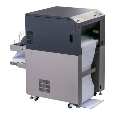
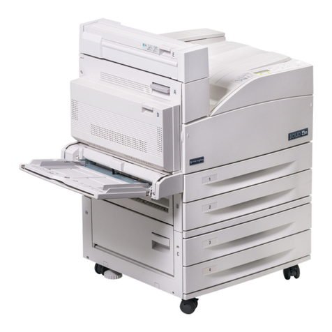
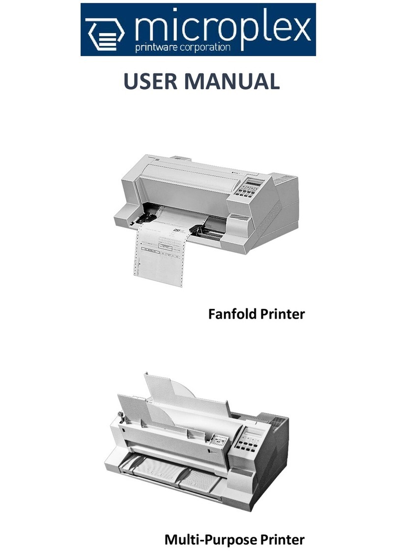
Microplex SOLID F90 HD User manual

________________________________________________________________________________
________________________________________________________________________________
SOLID F90 HD
Operator’s Manual
Edition 1.0

2
_______________________________________________________________________________________________
_______________________________________________________________________________________________

Table of Contents 3
_______________________________________________________________________________________________
_______________________________________________________________________________________________
MICROPLEX Operator’s Manual SOLID F90 HD Edition 1.0
Table of Contents
Chapter Page
1. Introduction 7
1.1. General Description 7
1.2. Conventions 9
1.3. CE — Conformity 10
1.4. General Safety Instructions 11
2. Installation 13
2.1. Check List 13
2.2. Printer Installation (Environment and Power Standards) 14
2.3. Printer Components 16
3. Handling of Consumables 19
3.1. Loading Paper 19
3.2. Replacing the Toner Cartridge 24
3.3. Replacing the Waste Toner Bottle 28
4. Operation and Menu Structure 31
4.1. Attaching the Printer to a Computer 31
4.2. Printer Power on 31
4.3. Control Panel View 32
4.4. Function of the Control Panel Elements 33
4.5. Configuration via the Control Panel 36
4.6. Menu Structure 38
4.7. Syntax of Diagrams 42

4 Table of Contents
_______________________________________________________________________________________________
_______________________________________________________________________________________________
MICROPLEX Operator’s Manual SOLID F90 HD Edition 1.0
Chapter Page
5. Panel Functions 43
5.1. Printing the Status Sheet 43
5.2. Printing the Font List 45
5.3. Choosing Print Resolution 46
5.4. Hexdump Mode Activation 48
5.5. Normal Print Mode Activation (incl. FORM FEED) 49
5.6. Clearing the Input Buffer (Cancel Job) 50
5.7. Printing the Menu Page 51
5.8. Generating Test Prints (Sliding Pattern) 52
5.9. Page Length Adjustment 54
5.10. Selecting the Number of Printpages per Page Format (Two-Up Mode) 56
5.11. Paper Width Adjusting (Format Width) 58
5.12. Print Direction Selection 59
5.13. Data Interface Configuration 60
5.14. Emulation Selection 61
5.15. Display Language Selection 63
5.16. Transparent Code Adjustment 64
5.17. Selection of Memory Distribution (Input Buffer) 65
5.18. Setting to Factory Default 66
5.19. Font Selection 67
5.20. Text Orientation Selection 70
5.21. Symbol Code Selection 71
5.22. Configuration of Text Margins 72
5.23. Image Shifting to the X-Direction 73
5.24. Image Shifting to the Y-Direction 75
5.25. Lines per Inch Setting (Line Spacing) 77
5.26. Number of Characters per Inch Setting (Character Spacing) 78
5.27. Print Density Setting 79
5.28. Configuration of Network Parameters (IP Address, e.g.) 80
6. Printer Cleaning 83
6.1. Cleaning the Elements behind the Front Cover 84
6.2. Cleaning the Transport Unit 88
6.3. Cleaning the Paper Feed Unit 91
6.4. Cleaning the Paper Near End Sensor 92
6.5. Cleaning the Power Stacker 93
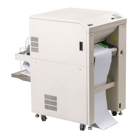
Table of Contents 5
_______________________________________________________________________________________________
_______________________________________________________________________________________________
MICROPLEX Operator’s Manual SOLID F90 HD Edition 1.0
Chapter Page
7. Operator Maintenance 95
7.1. Charger Cleaning 95
7.1.1. Main Charger Cleaning 96
7.1.2. Pre-Charger Cleaning 100
7.1.3. Transfer-/Separator Charger Cleaning 102
7.2. Developer Unit Cleaning 105
7.3. Developer Unit Refurbish, Developer Powder Exchange 110
7.4. Main Charger Replacing 117
7.5. Pre-Charger Replacing 118
7.6. Transfer-/Separator Charger Replacing 120
7.7. Photoreceptor Drum Exchange 122
8. Troubleshooting 131
8.1. Reduced Print Quality 132
8.2. Error Messages 133
8.2.1. Further Error Messages and Error Codes 136
8.3. Paper Jam 139
8.3.1. Paper Jam inside the Tractor 139
8.3.2. Paper Jam inside the Print System 140
8.3.3. Paper Jam within the Power Stacker 145
8.4. Print Repetition after an Error 146
9. Measures for Transport and Shipping (Repacking) 147
10. Specifications 149
11. Index 153

6 Table of Contents
_______________________________________________________________________________________________
_______________________________________________________________________________________________
MICROPLEX Operator’s Manual SOLID F90 HD Edition 1.0

Introduction 7
_______________________________________________________________________________________________
_______________________________________________________________________________________________
MICROPLEX Operator’s Manual SOLID F90 HD Edition 1.0
1. Introduction
1.1. General Description
The print system SOLID F90 HD works on an electrophotographical
base employing an LED array as exposure unit. The maximum
resolution of 600 dots per inch is corresponding to about 24 pixels
per mm.
The print speed is up to 85 pages per minute in the Two-Up mode .
Exclusively continuous media with sprocket holes can be used for the
tractor guiding. The maximum material width is 18 inches, the
printable width is 17 inches. This enables you to print two A4
portrait pages side by side (Two-Up). A stacker is included in the
standard device.
The non-contact Xenon flash fusing system in combination with the
straight paper flow enables you to use the most different paper types
and label materials with a weight from 60 to 204 g/m². Even
demanding media like plastic, PVC etc. can be used.
Consequently there is a multitude of scopes for this print system. It is
suitable for high-speed printing with excellent print quality using
different types of materials.
The high functionality of the MICROPLEX controller specially
qualifies the SOLID F90 HD also for form printing.
The printer is capable of using most of the page description
languages used in the industrial field and also the business standards
known in connection with laser printers can be used.
The capabilities featured include the MICROPLEX page description
language IDOL. Using this language, complex tasks such as the
creation of forms can be carried out by simple software commands
(see separate IDOL manual).
Data can be sent from almost any software platform, because printer
drivers are already available for this.

8 Introduction
_______________________________________________________________________________________________
_______________________________________________________________________________________________
MICROPLEX Operator’s Manual SOLID F90 HD Edition 1.0
The MICROPLEX printer controller has its integrated website, this allows
a printer configuration via Ethernet. See Networking Features of
MICROPLEX Printers for more information.
Consequently there is a multitude of scopes for this print system. It is
suitable for high-speed printing with excellent print quality using different
types of materials.
Printing Basics
The MICROPLEX printer controller enables the connection of this print
system to EDP systems whereby several interfaces, emulations and fonts
are available.
The digital information (e.g. a text file) is transferred from the computer
into the printer memory. The printer’s electronic component (the
controller) combined with the page description language, defines the
letters, numbers, graphics, etc. into bit patterns and posts them into the
controller’s frame store.
In this way, a “pattern“ of the future print page (generated by dots) is
created.
The electronically controlled LED (Light Emitting Diode Array) plots the
dot pattern in rows onto the light-sensitive surface of a rotating pre-
charged drum. Toner is caused to adhere to the electrostatic latent
image formed on the drum surface. This image consisting of toner
particles is electrically transferred onto the paper, that is guided past the
drum.
When transported further, the toner particles, which are affected by the
Xenon flash fusing, are combined resistantly with the paper. The drum is
discharged and cleaned.

Introduction 9
_______________________________________________________________________________________________
_______________________________________________________________________________________________
MICROPLEX Operator’s Manual SOLID F90 HD Edition 1.0
1.2. Conventions
!
ONLINE
blue colored text
[ Menu Level 1 ]
The following conventions should help you to find information
and to understand instructions more easily:
This symbol refers to a possible source of danger. Disregarding
the information identified by this symbol could result in injuries,
a reduction of printer functionality, or damage to the printer or
other objects.
This symbol indicates important hints and suggestions on using
the printer. Disregarding the hints might cause problems with
the printer or within the environments.
This symbol shows a control panel key. Such symbols will be
used in this manual whenever keys have to be pressed in order
to activate certain functions.
Link to another chapter or a different document. By clicking the
blue colored text you'll enter the concerning chapter or
document.
This symbol represents messages shown in the display (panel).
This symbol is used to show a shining LED (light emitting diode).
The SOLID F90 HD printer panel is provided with several LEDs.
The real shape of the LEDs differs from the shape of this symbol
(compare figure in section 4.3).
This symbol will be used in this manual to show a non-shining
LED.

10 Introduction
_______________________________________________________________________________________________
_______________________________________________________________________________________________
MICROPLEX Operator’s Manual SOLID F90 HD Edition 1.0
1.3. CE — Conformity

Introduction 11
_______________________________________________________________________________________________
_______________________________________________________________________________________________
MICROPLEX Operator’s Manual SOLID F90 HD Edition 1.0
1.4. General Safety Instructions
This device produces, employs and possibly radiates high
frequency energy. Because of this, incorrect installation can
disturb radio communications.
This MICROPLEX product and its consumables are designed
and tested according to strict safety standards.
Heeding the following instructions ensures secure operation:
- Make sure that your electricity source is grounded adequately.
- Install the device on solid and level ground.
- Only trained staff is authorized to transport the equipment.
- Only use consumables which are specially developed for this
device.
- Unsuitable consumables may reduce printer output quality or
cause damages.
- No liquids should get on or into the device.
- Do not remove any cover or safety device fastened by screws.

12 Introduction
_______________________________________________________________________________________________
_______________________________________________________________________________________________
MICROPLEX Operator’s Manual SOLID F90 HD Edition 1.0
- Do not bridge a safety device.
- Do not push anything into the ventilation apertures.
- Never perform installations, cleanings or maintenance work
that is not described in this manual. Such work should only be
done by MICROPLEX authorized service personnel.
- To avoid damage, the devices must be switched off (i.e. cut
off from the power supply) before the user begins connecting
the interface line.
In case of emergency, in order to disconnect the printer from the
main power, please note the following:
- For connected printers with plugs, an easily accessible power-
outlet should be installed near the printer.
- For permanently connected printers, an easily accessible
emergency power-off switch should be installed close to the
printer.
- Please do not conceal any disconnect devices with the printer
or other objects.
- Please follow all the information and hints directly attached to
the device and/or described in this manual.
- To ensure optimum printer performance, only use
MICROPLEX consumables.

Installation 13
_______________________________________________________________________________________________
_______________________________________________________________________________________________
MICROPLEX Operator’s Manual SOLID F90 HD Edition 1.0
2. Installation
2.1. Check List
First, place the printer and the accessories onto a level surface until
the definitive location is chosen.
Please make sure that all items are included and that there are no
defects. Immediately inform your supplier of any damage.
Open the cardboard box carefully and check the contents:
1. MICROPLEX Printer SOLID F90 HD
2. Developer Unit
3. Developer (powder)
4. Toner
5. Photoreceptor Drum
6. Cleaning Unit
7. Stacker
8. CD containing:
•Operator’s Manual SOLID F90 HD
•Print drivers
•IDOL Programming Manual
!The printer’s first installation has to be done by a trained service
engineer.
!Please retain the original packing materials in case the printer has
to be transported in the future.
Use the original packing materials and adhesive fasteners to avoid
damage to the internal components.
(See chapter 9 Measures for Transport and Shipping (Repacking)).

14 Installation
_______________________________________________________________________________________________
_______________________________________________________________________________________________
MICROPLEX Operator’s Manual SOLID F90 HD Edition 1.0
2.2. Printer Installation (Environment and Power Standards)
Fig. 2.2.a SOLID F90 HD: Required space (plan view)
- The chosen location should be well ventilated.
- Damaging environmental factors such as metal vapors, oil mist,
corroding lixivium or the like must not come in contact with the
printer.
- Position the printer on solid and level ground.
- Do not expose the printer to shocks or vibrations.
- The printer should not be located near volatile or combustible
materials (e.g. a curtain).
!The printer’s first installation has to be done by a trained service
engineer.
Space required for maintenance service
Space required for usual printer operation
1000 1000
800 800
1 0 0 0 1 0 0 0
5 0 0
78 0
Space required when
front cover is open
( Unit : mm )
SOLID F90 HD
1320
Stacker
Front cover

Installation 15
_______________________________________________________________________________________________
_______________________________________________________________________________________________
MICROPLEX Operator’s Manual SOLID F90 HD Edition 1.0
!
- Avoid locating the printer close to an air current ( e.g. ventilators).
- The printer should not be exposed to direct sunlight.
- Do not touch the drum surface because the material is easy to
damage.
- Do not expose the printer to abrupt temperature changes.
- In order to run the printer reliably, please maintain the following
environmental conditions:
Temperature: +15°C to +30°C (59°F to 86°F) operating
-10°C to +35°C (14°F to 95°F) non-operating
Relative humidity: 30% to 80% operating
10% to 80% non-operating
Power standards:
- Please connect the power plug to
230 V AC, 50 Hz (Europe, United Kingdom e.g.).
- The max. effective power input is appr. 5.5 kVA.
- The voltage support must not be impaired by interference.
- The printer is provided with a flexible 3x2.5 mm² connection cable
including a CEE plug 3x32. The corresponding CEE socket has to
be provided with a ≥25A fuse.
- If using an equivalent fixed connection ensure the grounding is
effected.
- Use the printer only within the allowable fluctuation range +10%
of the power voltage.
Conditional connection for the SOLID F90 HD:
The maximum permissible system impedance Zmax is appr. 0.02 Ohm.
The user of this device has to determine in consultation with the supply
authority, if necessary, that the equipment is connected only to a
supply of that impedance or less!
!To avoid damage, the devices must be switched off (i.e. cut off
from the power supply) before the user begins connecting the
interface line.

16 Installation
_______________________________________________________________________________________________
_______________________________________________________________________________________________
MICROPLEX Operator’s Manual SOLID F90 HD Edition 1.0
2.3. Printer Components
External Views:
Tractor
Control
panel
Lower
Front cover
Front cove
r
Power switch
Paper near end
sensor

Installation 17
_______________________________________________________________________________________________
_______________________________________________________________________________________________
MICROPLEX Operator’s Manual SOLID F90 HD Edition 1.0

18 Installation
_______________________________________________________________________________________________
_______________________________________________________________________________________________
MICROPLEX Operator’s Manual SOLID F90 HD Edition 1.0
Printer interior view:
Front cover
Drum plate
Toner cartridge
Cleaning unit
Developer unit
Power supply
for flash lamp
Transport
unit
Main charger
Waste toner
recovery unit
Fuser unit

Handling of Consumables 19
_______________________________________________________________________________________________
_______________________________________________________________________________________________
MICROPLEX Operator’s Manual SOLID F90 HD Edition 1.0
3. Handling of Consumables
3.1. Loading Paper
!
!
The printer processes continuous paper in lengths from 7 to 24
inches and width from 6 to 18 inches (including the perforated
margins, 17 inches printable).
You can check the printer configuration (inclusive the settings
regarding paper length etc.) by printing a status sheet (see
section 5.1).
If a large quantity of paper with a paper width smaller than
18 inch has been processed, the printer has to be cleaned first
before you start to process paper with a larger paper width.
See chapter 6 Printer Cleaning (especially section 6.2
Cleaning the Transport Unit) and chapter 7 Operator
Maintenance (especially section 7.1 Charger Cleaning).
1. Turn the printer OFF LINE.
2. Make sure the left tractor is in the left position.
Left Tractor

20 Handling of Consumables
_______________________________________________________________________________________________
_______________________________________________________________________________________________
MICROPLEX Operator’s Manual SOLID F90 HD Edition 1.0
3. Place the box containing the fanfold paper below the tractor
unit as shown below.
Mark for the left
paper margin
4. Pass the fanfold paper through the sensor guide (Paper
Near End Sensor PNES).
Folded edge of the paper
Guide with
paper sensor
Table of contents
Other Microplex Printer manuals

Microplex
Microplex iF60C User manual

Microplex
Microplex SOLID 60E-2 User manual

Microplex
Microplex PP 803 User manual

Microplex
Microplex SOLID T8 User manual

Microplex
Microplex PP 404 User manual

Microplex
Microplex SOLID F40 User manual

Microplex
Microplex logiJET TM4 User manual

Microplex
Microplex LOGIJET TC8 User manual

Microplex
Microplex F36C User manual

Microplex
Microplex SOLID 166E User manual