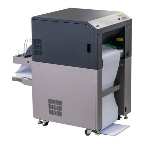
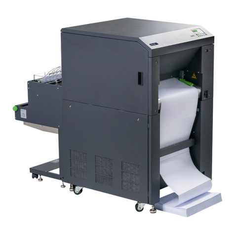
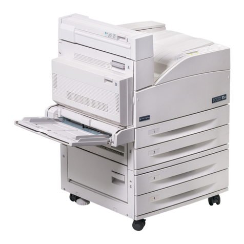
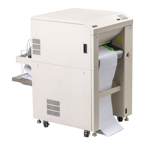
Microplex LOGIJET TC8 User manual

________________________________________________________________________________
________________________________________________________________________________
LOGIJET TC8
Operator’s Manual
Edition 1.1L

_______________________________________________________________________________________________
_______________________________________________________________________________________________

Contents 3
_______________________________________________________________________________________________
_______________________________________________________________________________________________
MICROPLEX Operator’s Manual LOGIJET TC8 Edition 1.1
Table of Contents
Chapter Page
1. Introduction 7
1.1. General Description 7
1.2. Fundamentals of Thermal Printing 8
1.3. Conventions 9
1.4. CE — Conformity 10
1.5. General Safety Regulations 11
2. Installation 13
2.1. Printer Unpacking 13
2.2. Check List 15
2.3. Printer Installation 17
2.4. Printer Components 18
3. Media and Ribbon Requirements 21
4. Basic Operation Sequences 23
4.1. Overview 23
4.2. Characteristics of the LOGIJET TC8 24
5. Handling of Consumables 25
5.1. Continuous Media Handling 27
5.1.1. Media Loading 27
5.1.2. Media Removal 35
5.2. Handling of Ribbon (Foil) 38
5.2.1. Adjusting the Ribbon Mandrels 38
5.2.2. Ribbon Loading 41
5.2.3. Ribbon Tension Adjustment 50
5.2.4. Ribbon Removal 53
5.3. Printhead Pressure Adjusting 59

4 Contents
_______________________________________________________________________________________________
_______________________________________________________________________________________________
MICROPLEX Operator’s Manual LOGIJET TC8 Edition 1.1
Chapter Page
6. Operation and Menu Structure 63
6.1. Attaching the Printer to a Computer 63
6.2. Turning on the Printer 63
6.3. Control Panel View 65
6.4. Function of the Control Panel Elements 65
6.5. Configuration via the Control Panel 68
6.6. Menu Structure 70
6.7. Syntax of Diagrams 74
7. Panel Functions 75
7.1. Media Setting (Material; Label or Continuous) 76
7.2. Page Length Adjustment 77
7.2.1. Starting the (Printer’s) Measurement of Label Length 78
7.2.2. Configuration of Semiautomatic Label Length Measurement 78
7.3. Material Width Adjustment (Paper Width) 79
7.4. Configuration of Text Margins 80
7.5. Printing the Status Sheet 81
7.6. Printing the Font List 83
7.7. Hexdump Mode Activation 84
7.8. Normal Print Mode Activation (incl. FORM FEED) 85
7.9. Clearing the Input Buffer (Cancel Job) 86
7.10. Printing the Menu Page 87
7.11. Generating Test Prints (Sliding Pattern) 88
7.12. Data Interface Configuration 89
7.13. Emulation Selection 90
7.14. Display Language Selection 92
7.15. Transparent Code Adjustment 93
7.16. Selection of Memory Distribution (Input Buffer) 94
7.17. Setting to Factory Default 95
7.18. Font Selection 96
7.19. Text Orientation Selection 99
7.20. Symbol Code Selection 100
7.21. Print Speed Adjustment 101
7.22. Contrast (Density) Setting 102

Contents 5
_______________________________________________________________________________________________
_______________________________________________________________________________________________
MICROPLEX Operator’s Manual LOGIJET TC8 Edition 1.1
Chapter Page
7.23. Image Shifting to the X-Direction 103
7.24. Image Shifting to the Y-Direction 105
7.25. Aligning the Colors to each other (Color Image shifting X/Y-direction) 107
7.26. Selecting and Adjusting the Sync Sensor 108
7.26.1. Selecting the Light Sensor Type (Gap or Reflex) 108
7.26.2. Checking and Adjusting the Position of the Sensors 109
7.26.3 Automatic Adjust of Level and Current 114
7.26.3.1. Overview 114
7.26.3.2. Example 115
7.26.4 Manual Adjusting of Level and Current 116
7.26.4.1. Overview: 117
7.26.4.2. Description of the Working Steps 118
7.26.4.3. Example 119
7.27. Adjusting the Zero Position of the Material Transport (Sync.Sens.Offset) 121
7.28. Peripheral Device Activation (Tear Off Edge, Cutter) 123
7.29. Selecting the Tear Off Mode (Option: Cutting Mode) 125
7.30. Selecting the Print Mode 127
7.31. Adjusting the Tear Off Position (Option: Cutting Position) 130
7.32. Configuration of Network Parameters (IP Address, e.g.) 132
8. Operator Maintenance 135
8.1. Printer Cleaning 135
8.1.1. Printer Cabinet Cleaning 136
8.1.2. Cleaning the Printheads 137
8.1.3. Platen Roller Cleaning 141
8.1.4. Cleaning the Sensors 144
8.2. Avoiding Ribbon Slack and Wrinkles 147
8.3. Check the Printhead Pressure 153
9. Troubleshooting 154
9.1. Error Messages 155
9.2. Reduced Print Quality 158
9.3. Incorrect Media Transport 160
9.4. Clearing Paper Jam 162
9.5. Print Repetition after an Error 165

6 Contents
_______________________________________________________________________________________________
_______________________________________________________________________________________________
MICROPLEX Operator’s Manual LOGIJET TC8 Edition 1.1
Chapter Page
10. Measures for Transport and Shipping (Repacking) 166
11. Specifications 167
12. Appendix 171
12.1. Color Printing with LOGIJET TC8 171
12.2. Basically Approach for Generating Colors 171
12.3. Using the Windows Printer Driver 173
12.3.1. Plug and Play Installation 173
12.3.2. Using the Add Printer Wizard 173
12.3.3. How to access the Driver Screens 174
12.3.4. Driver Settings 175
12.4. Color Support by several Emulations 179
12.4.1. IDOL 179
12.4.2. IGP 180
12.4.3. CODE V 181
12.4.4. Prescribe IIe 182
12.4.5. Epson FX (ESC/P) 182
13. Index 183

Introduction 7
_______________________________________________________________________________________________
_______________________________________________________________________________________________
MICROPLEX Operator’s Manual LOGIJET TC8 Edition 1.1
1. Introduction
1.1. General Description
The LOGIJET TC8 is a 2-color thermal printer perfectly suited for
industrial applications. This printer is equipped with two robust print
modules which can be loaded with ribbons of different colors.
Therefore the printer can be used, for example, for the individual
printing of hazard warning labels in production, chemical,
pharmaceutical, food industry and so on.
This printer is PCL-5 compatible and can thus be operated like a laser
printer. In this way it is not necessary to put up with adaptations and
power drains at SAP-applications or in the progress of changing from
a laser printer to this thermal printer.
The LOGIJET TC8 printer can be used for printing on roll-fed media
as well as for printing on fanfold media. The maximum processable
width of media is 9” (228 mm). Up to 8.64” (219 mm) of that are
printable. The printer is equipped with sensors for Black Mark and
Gap (reflex and transparent).
The wide-opening printheads allow easy access to the media and
the ribbons. Therefore the loading of consumables is quick and
easy.
The print speed is up to up to 6 Inch / second (150 mm / second).
The resolution is 300 dots per inch corresponding to about 12 dots
per millimeter.
The LOGIJET TC8 is provided with a controller that is also used in
SOLID laserprinters. So the advantages of the thermal print
technology are combined with the flexibility of the „laserprinter
intelligence“.
The MICROPLEX printer controller has its integrated website, this
allows a printer configuration via Ethernet. See Networking Features
of MICROPLEX Printers for more information.
Data can be sent without programming expenditure from almost
any software platform, because printer drivers are already
available for this.
8 Introduction
_______________________________________________________________________________________________
_______________________________________________________________________________________________
MICROPLEX Operator’s Manual LOGIJET TC8 Edition 1.1
The capabilities featured include the MICROPLEX page description
language IDOL. Using this language, complex tasks such as the
creation of forms can be carried out by simple software commands
(see separate IDOL manual).
1.2. Fundamentals of Thermal Printing
The thermal print technology enables a quiet and fast print process
with a high resolution output. The printhead produces the image by
heating single elements (dots). So you need a special ribbon (thermal
transfer printing). Ribbons with different colors are available.
While thermal transfer printing the dots touch the thermal ribbon so
that the heating of particular dots leads to a partial melting of the
ribbon. Due to the contact with a media (future carrier of the
information, for example paper) this leads to a transfer of the image
onto the media.

Introduction 9
_______________________________________________________________________________________________
_______________________________________________________________________________________________
MICROPLEX Operator’s Manual LOGIJET TC8 Edition 1.1
1.3. Conventions
!
blue colored text
[Menu Level 1 ]
To find the requested information more quickly and to
understand instructions more easily, the following conventions
are used:
This symbol refers to a possible source of danger. If you do not
pay attention to this information, injuries may result, the function
of the printer could be reduced or objects could be damaged.
This symbol refers to important hints and suggestions on using
the printer. Disregarding these hints might cause problems with
the printer or within the environments.
This symbol shows a key of the control panel. Such symbols will
be used in this manual whenever keys have to be pressed in
order to activate certain functions.
Link to another chapter or a different document. By clicking the
blue colored text you'll enter the concerning chapter or
document.
This symbol represents messages shown in the display (panel).

10 Introduction
_______________________________________________________________________________________________
_______________________________________________________________________________________________
MICROPLEX Operator’s Manual LOGIJET TC8 Edition 1.1
1.4. CE — Conformity

Introduction 11
_______________________________________________________________________________________________
_______________________________________________________________________________________________
MICROPLEX Operator’s Manual LOGIJET TC8 Edition 1.1
1.5. General Safety Regulations
This equipment generates, uses, and can radiate radio
frequency energy and, if not installed and used in accordance
with the instruction manual, may cause harmful interference to
radio communications. Incorrect operation of this equipment in
a residential area is likely to cause harmful interference in
which case the user will be required to correct the interference
at his own expense.
This MICROPLEX product and its consumables are designed
and tested according to strict safety standards.
Heeding the following instructions ensures secure operation:
- Please make sure your electricity source is appropriately
grounded.
- Install the device on solid and level ground.
- Only trained staff are authorized to transport the equipment.
- Only use consumables which are specially developed for this
device.
- Using unsuitable consumables may cause a reduction of output
quality or damages to the device.
- Ensure no liquids get on or into the device.
- Do not remove any cover or safety device fastened by screws.
- Do not remove or bridge over any safety device.

12 Introduction
_______________________________________________________________________________________________
_______________________________________________________________________________________________
MICROPLEX Operator’s Manual LOGIJET TC8 Edition 1.1
- Do not push anything into the ventilation apertures.
- Never carry out installations, cleanings or maintenance
operations which are not described in this manual. This
should only be done by MICROPLEX authorized service
personnel.
- Be careful when operating equipment with opened cover
hoods (setting-up work or service). Rotating parts can cause
injury , and it is also possible for hair, clothing, jewellery,
etc. to be caught in the machinery.
Ribbon and material should only be inserted and changed by
specially instructed personnel.
- Optional device components may only be installed by
authorized personnel, and in accordance with the
appropriate assembly and usage regulations.
- Only plug in or remove interface connectors when the device
is switched off.
In order to disconnect the printer quickly from the main power
in case of emergency please note the following:
- For connected printers with plugs, the power-outlet should
be installed near the printer and easily within reach.
- For permanently connected printers, an easily accessible
emergency power-off switch should be installed close to the
printer.
- Please do not conceal any disconnect devices with the
printer or other objects.
- After switching off the device, wait at least 15 seconds
before the device is switched on again.
- Please follow all the information and hints directly attached
to the device and/or described in this manual.

Installation 13
_______________________________________________________________________________________________
_______________________________________________________________________________________________
MICROPLEX Operator’s Manual LOGIJET TC8 Edition 1.1
2. Installation
2.1. Printer Unpacking
1. Open the box and and remove the packing materials lying on top
to lay open the upper foam damper.
2. Remove the printer accessories, if need be.
Fig. 2.1.a Printer with packing materials
3. Take out the upper foam damper.

14 Installation
_______________________________________________________________________________________________
_______________________________________________________________________________________________
MICROPLEX Operator’s Manual LOGIJET TC8 Edition 1.1
4. Take the printer and lift it out the box carefully.
Get somebody to help you to lift the printer, if necessary.
Take hold of the printer from the bottom of the printer itself.
Get somebody to hold the lower foam damper and the box when
removing the printer.
5. Place the printer onto a suitable base (see chapter 2.3).
Please retain the original packing materials in case the printer
has to be transported in the future.

Installation 15
_______________________________________________________________________________________________
_______________________________________________________________________________________________
MICROPLEX Operator’s Manual LOGIJET TC8 Edition 1.1
2.2. Check List
First of all place the printer and the accessories onto a level
surface until the definitive location is chosen.
Please make sure that all items are included and that there are
no defects.
Immediately inform your supplier of any damage.
Open the cardboard box carefully and check the contents
(compare figure 2.2.a, too):
1. Printer LOGIJET TC8
2. Power cord
3. Ribbon takeup core (option)
4. Ribbon mandrels (4 pieces)
5. CD containing:
•Operator’s Manual for LOGIJET TC8
•Print drivers
•IDOL Programming Manual

16 Installation
_______________________________________________________________________________________________
_______________________________________________________________________________________________
MICROPLEX Operator’s Manual LOGIJET TC8 Edition 1.1
Fig. 2.2.a Accessories for the LOGIJET TC8 (some of them are optional)
"
CD
(in total
4 peaces)

Installation 17
_______________________________________________________________________________________________
_______________________________________________________________________________________________
MICROPLEX Operator’s Manual LOGIJET TC8 Edition 1.1
2.3. Printer Installation
- The chosen location should be well-ventilated, clean and dry.
- Damaging environmental factors such as metal vapors, oil mist,
corroding lixivium or the like must not come into contact with
the printer.
- Position the printer on solid and level ground.
- Do not exposure the printer to shocks or vibrations.
- The printer and socket have to be easily accessible.
- The printer should not be located near volatile or combustible
materials (e.g. a curtain).
- The printer must be connected to an appropriate AC power
source: 100 — 240 V AC ( - 10%, + 6%), 3.2 — 6.4 A, 50/60 Hz
The power source must be properly grounded.
The socket and power cords must not be damaged.
- Use the printer only within the allowed fluctuation range
(the allowed values are listed above).
- The voltage support must not be impaired by interference.
- In order to run the printer reliably, please maintain the
following environmental conditions:
Temperature: +5°C to +35°C
-20°C to +60°C (storage temperature)
Relative atmospheric humidity: 45% to 75% (without
condensation)
- Do not expose the printer to abrupt temperature changes
(heating, window or air condition).
- The printer should not be exposed to direct sunlight.

18 Installation
_______________________________________________________________________________________________
_______________________________________________________________________________________________
MICROPLEX Operator’s Manual LOGIJET TC8 Edition 1.1
2.4. Printer Components
Main view:
Fig. 2.4.a Main view of the printer
Display
Control Panel
LCD grafics display;
2 LEDs and 6 keys;
Displays printer operation
status, enables settings
via the menu.
Paper output
Top cover
Open to insert
material and foil.

Installation 19
_______________________________________________________________________________________________
_______________________________________________________________________________________________
MICROPLEX Operator’s Manual LOGIJET TC8 Edition 1.1
Rear view:
Ethernet interface
Centronics - interface
USB interface
Input power connector
Power switch
RS232/RS422
-interface
Fig. 2.4.b Rear view of the printer
Fig. 2.4.c Opening the printer’s top cover
Embossed
patterns on
the surface
Top cover
of the printer
#
Embossed
patterns on
the surface

20 Installation
_______________________________________________________________________________________________
_______________________________________________________________________________________________
MICROPLEX Operator’s Manual LOGIJET TC8 Edition 1.1
Printer interior view:
Front paper
guide
Rear print
h
ea
d
(Print unit 1)
Front platen roller
Lo
w
er sensor
(Reflex sensor)
Rear platen roller
Uppe
r
senso
r
(Transparent
sensor)
Transparent
sensor guide
Front printhead
(Print unit 2)
Tear ba
r
Rear paper
guide
Fig. 2.4.d Printer opened
Ribbon mandrel
holder
Transparent sensor guide
release lever
Printhead release
lever
Ribbon
guide plate
Printhead adjustment leve
r
Fig. 2.4.e Details at the front print unit (and the rear print unit as well)
Other manuals for LOGIJET TC8
1
Table of contents
Other Microplex Printer manuals

Microplex
Microplex logiJET TM4 User manual

Microplex
Microplex F36C User manual

Microplex
Microplex SOLID 50 A3 - 3 User manual

Microplex
Microplex SOLID 166E User manual

Microplex
Microplex SOLID F90 HD User manual

Microplex
Microplex logiJET T4-2 User manual

Microplex
Microplex SOLID T8 User manual

Microplex
Microplex LOGIJET TC8 User manual

Microplex
Microplex SOLID 60E-2 User manual

Microplex
Microplex SOLID F44 User manual