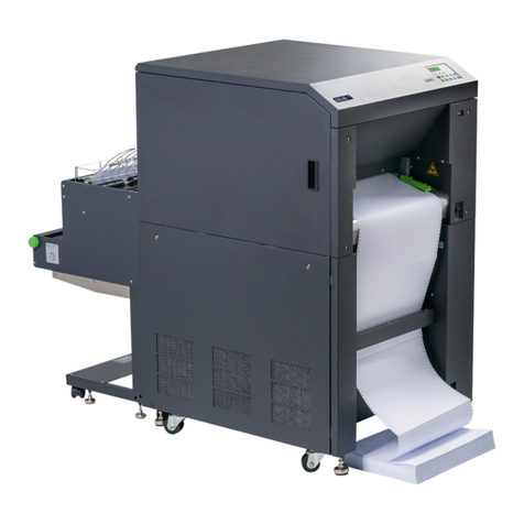
Microplex logiJET TM4 User manual

________________________________________________________________________________
________________________________________________________________________________
logiJET TM4
Operator’s Manual
Edition 1.2p

2
_______________________________________________________________________________________________
_______________________________________________________________________________________________
MICROPLEX Operator’s Manual logiJET TM4 Edition 1.2p
Protected Rights
In MICROPLEX documentations (Operator’s Manuals, Service Manuals etc.) product names are
generally given without any mention of existing patents, registered designs or trademarks. The
absence of a corresponding remark does not give any implication that the name can be used at
will. All trademarks are recognised as protected.
Alterations
No liability is assumed for the accuracy of the contents of the documentations. MICROPLEX
reserves the right to alter technical or other specifications with no prior notice. Deviations in the
documentations from prevailing conditions do not represent an obligation to redeliver.
Product Properties
Due to continuous updating of the products deviations between the documentations and the
relating product can occur.
The manufacturer does not guarantee the existence or non-existence of properties with the
description of subject contents in the documentations. Nor does the manufacturer give any express
or tacit guarantee declarations whatsoever.

Contents 3
_______________________________________________________________________________________________
_______________________________________________________________________________________________
MICROPLEX Operator’s Manual logiJET TM4 Edition 1.2p
Table of Contents
Chapter Page
1. Introduction 7
1.1. General Description 7
1.2. Fundamentals of Thermal Printing 8
1.3. Conventions 9
1.4. General Safety Regulations 10
2. Installation 13
2.1. Printer Unpacking 13
2.2. Check List 15
2.3. Printer Installation 16
2.4. Printer Components 17
3. Basic Operation Sequences 21
3.1. Overview 21
4. Handling of Consumables 23
4.1. Winding Diagram 24
4.2. Handling of Ribbon (Foil) 25
4.2.1. Ribbon Loading 25
4.2.2. Ribbon Removal 29
4.3. Roll-Fed Media Handling 30
4.3.1. Roll-fed Media Loading 30
4.3.2. Media Removal 41
5. Operation 43
5.1. Attaching the Printer to a Network/PC 43
5.2. Printer Power Supply 44
5.3. Control Panel View 46
5.3.1. Function of the Control Panel Elements 47
5.3.2. Setting to Factory Defaults 49

4Contents
_______________________________________________________________________________________________
_______________________________________________________________________________________________
MICROPLEX Operator’s Manual logiJET TM4 Edition 1.2p
Chapter Page
6. Access to the integrated Web Page of the logiJET TM4 51
6.1. Abstract 51
6.2. Connecting the Printer to the Network 51
7. Operating the Printer via the integrated Website (WebPanel) 53
7.1. Overview Page 53
7.2. Configuration Page 55
7.3. Page Setup Page 56
7.4. Network Page 57
7.5. Device Status Page 59
7.6. EEPROM Page 60
7.7. User Control Page 62
8. Operating the Printer via the IP-Admin Panel User Interface 63
8.1. IP-Admin Panel 64
8.1.1. Details of the IP-Admin Panel Elements 65
8.1.2. Configuration via the Control Panel 66
8.2. Menu Structure 68
8.2.1. Syntax of Diagrams 73
8.3. Panel Functions 74
8.3.1. Adjusting the Printer to the Print Material (Paper Type) 75
8.3.2. Adjusting the Sync Sensors 76
8.3.3. Print Process Selecting 89
8.3.4. Adjusting the Zero Position of the Material Transport (Sync.Sens.Offset) 91
8.3.5. Page Length Adjustment 93
8.3.6. Material Width Adjustment (Paper Width) 96
8.3.7. Configuration of Text Margins 98
8.3.8. Show Info (IP Address, Firmware Release …) 99
8.3.9. Printing the Status Sheet 100
8.3.10. Printing the Font List 102
8.3.11. Hexdump Mode Activation 103
8.3.12. Normal Print Mode Activation (incl. FORM FEED) 104

Contents 5
_______________________________________________________________________________________________
_______________________________________________________________________________________________
MICROPLEX Operator’s Manual logiJET TM4 Edition 1.2p
Chapter Page
8.3.13. Clearing the Input Buffer (Cancel Job) 105
8.3.14. Printing the Menu Page 106
8.3.15. Generating Testsheets (Sliding Pattern) 107
8.3.16. Print Direction Selection 108
8.3.17. Data Interface Configuration 109
8.3.18. Emulation Selection 110
8.3.19. Menu Language Selection 112
8.3.20. Transparent Code Adjustment 113
8.3.21. Selection of Memory Distribution (Input Buffer) 114
8.3.22. Setting to Factory Default 115
8.3.23. Font Selection 116
8.3.24. Print Speed Adjustment 119
8.3.25. Density (Contrast) Setting 120
8.3.26. Configuration of Network Parameters (IP Address, e.g.) 121
9. Operator Maintenance 125
9.1. Printer Cleaning 125
9.1.1. Printer Cabinet Cleaning 126
9.1.2. Printhead Cleaning 127
9.1.3. Platen Roller Cleaning 129
10. Troubleshooting 131
10.1. Printer Error Messages 132
10.2. Reduced Print Quality 135
10.3. Incorrect Media Transport 137
10.4. Print Repetition after an Error 139
11. Measures for Transport and Shipping (Repacking) 141
12. Specifications 143
13. Index 147

6Contents
_______________________________________________________________________________________________
_______________________________________________________________________________________________
MICROPLEX Operator’s Manual logiJET TM4 Edition 1.2p

Introduction 7
_______________________________________________________________________________________________
_______________________________________________________________________________________________
MICROPLEX Operator’s Manual logiJET TM4 Edition 1.2p
1. Introduction
1.1. General Description
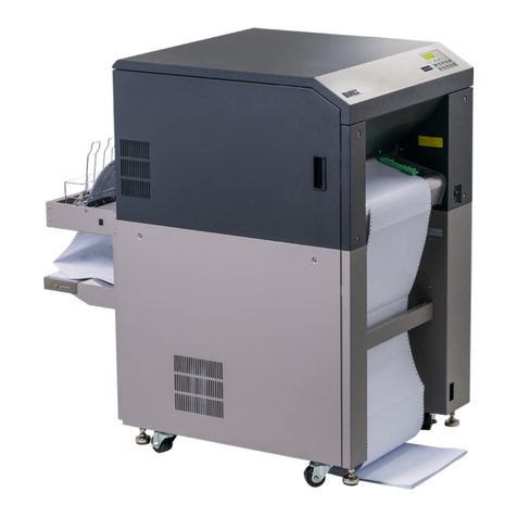
The logiJET TM4 is a multifunctional non-impact printer based on
thermal print technology. The very compact design, the sturdy metal
housing and the option to use supply voltages of 12V, 24V or 48V
make this device an ideal printer for so called “mobile printing”.
A so called mounting plate (option) can be used to fix this printer to
a forklift truck, for example.
The device can be used for thermal transfer printing as well as for
thermal direct printing. It can be used to print all kind of information
as barcodes, alphanumerical characters and vector graphics e.g. .
This printer not only knows one device-specific page description
language as standard thermal printers usually do, but most of the
languages used in the industrial field and the well-known market
standards of laserprinters, too.
For this printer options are available (for example, cutter).
The logiJET TM4 printer is provided with a controller that is also
used in SOLID laserprinters. So the advantages of the thermal print
technology are combined with the flexibility of the „laserprinter
intelligence“.
The MICROPLEX printer controller has its integrated website, this
allows a printer configuration via Ethernet. See Networking
Features of MICROPLEX Printers for more information.
Data can be sent without programming expenditure from almost
any software platform, because printer drivers are already
available for this.
The capabilities featured include the MICROPLEX page description
language IDOL. Using this language, complex tasks such as the
creation of forms can be carried out by simple software commands
(see separate IDOL manual).
The resolution is 300 dots per inch corresponding to about 12 dots
per mm.
8Introduction
_______________________________________________________________________________________________
_______________________________________________________________________________________________
MICROPLEX Operator’s Manual logiJET TM4 Edition 1.2p
The print speed is up to 6 inch/second (up to 150mm/second).
Roll-fed media as well as continuous-media can be printed on.
The minimum width of media is 25.4mm (1”). The maximum processable
width of media for the logiJET TM4 is up to 118mm (4.64”). 106mm
(4.17”) of that are printable.
1.2. Fundamentals of Thermal Printing
The thermal print technology enables a quiet and fast print process with a
high resolution output. The printhead produces the image by heating
single elements (dots). So you need a special ribbon (thermal transfer
printing) or a special kind of paper (thermal direct printing).
While thermal transfer printing the dots touch the thermal ribbon so that
the heating of particular dots leads to a partial melting of the ribbon. Due
to the contact with a media (future carrier of the information, for example
paper) this leads to a transfer of the image onto the media.
While thermal direct printing the dots touch the thermal paper directly.
The dyes and developers within the paper respond to the heat of
particular dots, change their colour to black and so the wanted image
emerges.
The printer logiJET TM4 can be used for both methods of printing.

Introduction 9
_______________________________________________________________________________________________
_______________________________________________________________________________________________
MICROPLEX Operator’s Manual logiJET TM4 Edition 1.2p
1.3. Conventions
blue colored text
[Menu Level 1 ]
To find the requested information more quickly and to
understand instructions more easily, the following conventions
are used:
This symbol refers to a possible source of danger. If you do not
pay attention to this information, injuries may result, the function
of the printer could be reduced or objects could be damaged.
This symbol refers to important hints and suggestions on using
the printer. Disregarding these hints might cause problems with
the printer or within the environments.
This symbol shows a key of the control panel.
Such symbols will be used in this manual whenever keys have to
be pressed in order to activate certain functions.
Link to another chapter or a different document. By clicking the
blue colored text you'll enter the concerning chapter or
document.
This symbol represents messages shown in the display (panel).

10 Introduction
_______________________________________________________________________________________________
_______________________________________________________________________________________________
MICROPLEX Operator’s Manual logiJET TM4 Edition 1.2p
1.4. General Safety Regulations
This device produces, employs and possibly radiates high
frequency energy. Because of this, incorrect installation can
disturb radio communications.
This MICROPLEX product and its consumables are designed and
tested according to strict safety standards.
Heeding the following instructions ensures secure operation:
- In both cases, while using the mains connection and while
“mobile printing”, please make sure your electricity source is
appropriately grounded.
- Set the DIPswitch located on the DC/DC converter PCB to the
nominal voltage supplied by the vehicle’s electric system and
always use a suitabele fuse (details are described in chapter 5).
- Install the device on solid and level ground.
For “mobile printing” the printer has to be fixed firmly to the
vehicle by using the so called mounting plate (option).
- Only use consumables which are specially developed for this
device.
- Using unsuitable consumables may cause a reduction of output
quality or damages to the device.

Introduction 11
_______________________________________________________________________________________________
_______________________________________________________________________________________________
MICROPLEX Operator’s Manual logiJET TM4 Edition 1.2p
- Ensure no liquids get on or into the device.
- Do not remove any cover or safety device fastened by screws.
- Do not remove or bridge over any safety device.
- Do not push anything into the ventilation apertures.
- Never carry out installations, cleanings or maintenance
operations which are not described in this manual. This should
only be done by MICROPLEX authorized service personnel.
- Be careful when operating equipment with opened cover
hoods (setting-up work or service). Rotating parts can cause
injury , and it is also possible for hair, clothing, jewellery,
etc. to be caught in the machinery.
Ribbon and material should only be inserted and changed by
specially instructed personnel.
- Optional device components may only be installed by
authorized personnel, and in accordance with the
appropriate assembly and usage regulations.
- The cutter may only be installed by trained personnel.
- Only attach or remove the printhead when the device is
switched off.
After switching off the device, wait at least 3 minutes before
removing the printhead.
- Only plug in or remove interface connectors when the device
is switched off.

12 Introduction
_______________________________________________________________________________________________
_______________________________________________________________________________________________
MICROPLEX Operator’s Manual logiJET TM4 Edition 1.2p
In order to disconnect the printer quickly from the main power
in case of emergency please note the following:
- If the printer is connected to the mains supply, the power-outlet
should be installed near the printer and easily within reach.
- For permanently connected printers, an easily accessible
emergency power-off switch should be installed close to the
printer.
- Please do not conceal any disconnect devices with the
printer or other objects.
- After switching off the device, wait at least 15 seconds
before the device is switched on again.
- Please follow all the information and hints directly attached
to the device and/or described in this manual.

Installation 13
_______________________________________________________________________________________________
_______________________________________________________________________________________________
MICROPLEX Operator’s Manual logiJET TM4 Edition 1.2p
2. Installation
2.1. Printer Unpacking
1. Open the box and remove the accessory parts.
Hint: The shipping box etc. of your printer may differ in
form and optic from the parts shown in the
following 2 figures.
Fig. 2.1.a Printer in the shipping box
2. Take the printer and lift it out the box carefully. Get
somebody to hold the box when removing the printer.
Take hold of the printer from the bottom.
Do not use other parts of the printer (e.g. plastic parts at the
printer's front or rear side ...) to lift the device!
Box contains
accessories
Printer

14 Installation
_______________________________________________________________________________________________
_______________________________________________________________________________________________
MICROPLEX Operator’s Manual logiJET TM4 Edition 1.2p
Fig. 2.1.b Lifting the printer
3. Remove the foil covering the printer.
4. Place the printer onto a suitable base (see section 2.3).
Please retain the original packing materials in case the printer
has to be transported in the future.

Installation 15
_______________________________________________________________________________________________
_______________________________________________________________________________________________
MICROPLEX Operator’s Manual logiJET TM4 Edition 1.2p
2.2. Check List
First of all place the printer and the accessories onto a level
surface until the definitive location is chosen.
Please make sure that all items are included and that there are
no defects.
Immediately inform your supplier of any damage.
Open the cardboard box carefully and check the contents:
1. Printer logiJET TM4
2. Power cord
3. Data cable (USB)
4. Ribbon supply spindle + Ribbon rewind spindle
(eventually both parts are already mounted in the device)
5. empty Ribbon Sleeve (Ribbon Core)
6. Two so called Spacers + two Centering sleeves, each with a
knurled screw (all these parts belong to the media supply
spindle, eventually these parts are already mounted in the
device)
7. CD containing:
Operator’s Manual for logiJET TM4
Print drivers
IDOL Programming Manual

16 Installation
_______________________________________________________________________________________________
_______________________________________________________________________________________________
MICROPLEX Operator’s Manual logiJET TM4 Edition 1.2p
2.3. Printer Installation
- The chosen location should be well-ventilated, clean and dry.
- Damaging environmental factors such as metal vapors, oil mist,
corroding lixivium or the like must not come into contact with
the printer.
- Position the printer on solid and level ground.
- Do not exposure the printer to shocks or vibrations.
- The printer and socket or rather the connection cables have to
be easily accessible.
- The printer should not be located near volatile or combustible
materials.
- The printer must be connected to an appropriate AC power
source 100 –240 VAC, 1.6 A, 50 - 60 Hz.
The socket and the power cord must not be damaged.
- If the printer is equipped with the corresponding option,
power sources with 12V, 24V or 48V can be used, too
(on-board-electrical system of a forklift truck, for example).
-Use the printer only within the allowed range of connection
values (see chapter Specifications).
- In order to run the printer reliably, please maintain the
following environmental conditions:
Temperature: +5°C to +40°C (operating)
-20°C to +50°C (storage temperature)
Relative atmospheric humidity: 30% to 85% (without
condensation)

Installation 17
_______________________________________________________________________________________________
_______________________________________________________________________________________________
MICROPLEX Operator’s Manual logiJET TM4 Edition 1.2p
2.4. Printer Components
Main view:
Fig. 2.4.a Main view of the printer logiJET TM4
Cover
Open to insert material
and foil.
Control Panel
2 keys + 2 LEDs
(they indicate the
printer’s operating
status)
Window
Check the material / foil
supply without opening
the cover.
Handle to open
the cover

18 Installation
_______________________________________________________________________________________________
_______________________________________________________________________________________________
MICROPLEX Operator’s Manual logiJET TM4 Edition 1.2p
Fig. 2.4.b Side view of the printer
Fig. 2.4.c Rear view of the printer
Interfaces
Option:
Switch + Socket
(12V, 24V, 48V)
Power switch +
Power socket
(100 - 240 V AC)

Installation 19
_______________________________________________________________________________________________
_______________________________________________________________________________________________
MICROPLEX Operator’s Manual logiJET TM4 Edition 1.2p
Fig. 2.4.d Inside View of the printer
Fig. 2.4.e Mounting Plate for the printer (this Mounting Plate is optional)
Fig. 2.4.f Mounting Plate: view from below
Printhead release
levers
Printhead unit
( here without
Ribbon,
R. supply spindle
and
R. rewind spindle)
Media supply
spindle
Locking device
(to get the printer
connected to the
mounting plate or to
release the mechanical
lock)

20 Installation
_______________________________________________________________________________________________
_______________________________________________________________________________________________
MICROPLEX Operator’s Manual logiJET TM4 Edition 1.2p
Details on mounting the printer to a forklift truck:
The Mounting Plate (optional part of the printer) is equipped with 4 rubber feet.
In the bottom of each foot there is a bore hole to incorporate a M4 fastening screw.
The following drawing of the Mounting plate shows the construction offsets of the 4
rubber feet:
Fig. 2.4.g Drawing of the 4 fixing holes in the Mounting Plate
Drill the 4 bore holes (threaded holes or through bores for M4 screws + nuts) into the the
surface of your forklift truck (matching the target position of the printer).
Notes on the electrical connection of the printer can be found in section 5.2
Printer Power Supply.
Please assemble the Mounting Plate to the forklift truck using four M4 screws.
Then assemble the printer logiJET TM4 to the Mounting Plate (the locking device must
engage, compare fig. 2.4.f).
Table of contents
Other Microplex Printer manuals

Microplex
Microplex F36C User manual

Microplex
Microplex SOLID F44 User manual

Microplex
Microplex SOLID F40 User manual

Microplex
Microplex iF60C User manual

Microplex
Microplex SOLID T11 DT User manual

Microplex
Microplex SOLID 60E-2 User manual

Microplex
Microplex LOGIJET TC8 User manual

Microplex
Microplex SOLID T8 User manual

Microplex
Microplex logiJET T4-2 User manual

Microplex
Microplex PP 404 User manual