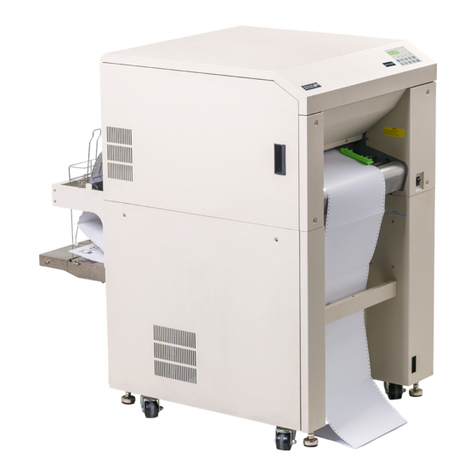
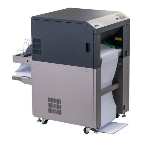
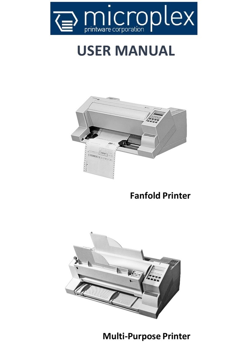
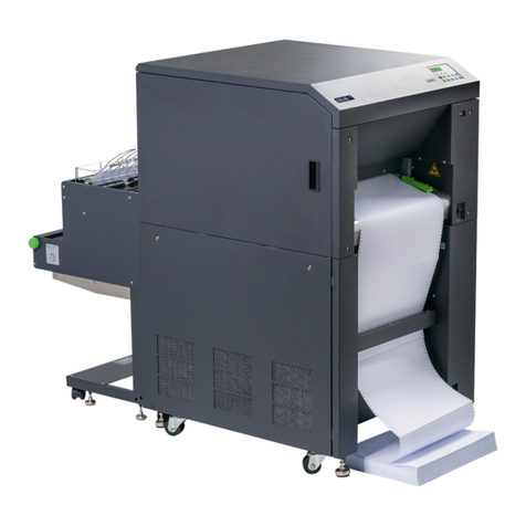
Microplex SOLID 50 A3 - 3 User manual

________________________________________________________________________________
________________________________________________________________________________
SOLID 50 A3 - 3
Operator’s Manual
Edition 2.1

2
_______________________________________________________________________________________________
_______________________________________________________________________________________________

Table of Contents 3
_______________________________________________________________________________________________
_______________________________________________________________________________________________
MICROPLEX Operator’s Manual SOLID 50 A3 - 3 Edition 2.1
Table of Contents
Chapter Page
1. Introduction 7
1.1. General Description 7
1.2. Conventions 9
1.3. CE - Conformity 10
1.4. General Safety Instructions 10
2. Installation 13
2.1. Check List 13
2.2. Printer Unpacking 14
2.3. Preparing the Printer 17
2.4. Printer Installation 26
2.5. Printer Components 30
3. Handling of Consumables 32
3.1. Print Media Handling (Paper, e.g.) 32
3.1.1. Loading Cassettes 1 and 2 32
3.1.2. Loading the Multipurpose Feeder 38
3.1.3. Using the Output Bins 41
3.1.4. Changing the Paper Size Setting 42
3.2. Toner Cartridge Replacing 44
3.3. Drum Cartridge Replacing 51
4. Operation and Menu Structure 59
4.1. Attaching the Printer to a Computer 59
4.2. Turning on the Printer 59
4.3. Control Panel View 61
4.4. Function of the Control Panel Elements 62
4.5. Configuration via the Control Panel 64
4.6. Menu Structure 65
4.7. Syntax of Diagrams 70

4Table of Contents
_______________________________________________________________________________________________
_______________________________________________________________________________________________
MICROPLEX Operator’s Manual SOLID 50 A3 - 3 Edition 2.1
Chapter Page
5. Panel Functions 71
5.1. Printing the Status Sheet 71
5.2. Printing the Font List 73
5.3. Choosing Print Resolution 74
5.4. Hexdump-Mode Activation 76
5.5. Normal Print Mode Activation (incl. FORM FEED) 77
5.6. Clearing the Input Buffer (Cancel Job) 78
5.7. Printing the Menu Page 79
5.8. Generating Testsheets (Sliding Pattern) 80
5.9. Feeder (Cassette) Selection 81
5.10. Stacker Selection 83
5.11. Print Mode Selection (Simplex/Duplex) 85
5.12. Paper Size Selection 87
5.13. Enabling Format Check 88
5.14. Print Direction Selection 89
5.15. Data - Interface Configuration 90
5.16. Emulation Selection 91
5.17. Display Language Selection 93
5.18. Transparent Code Adjustment 94
5.19. Selection of Memory Distribution (Input Buffer) 95
5.20. Setting to Factory Default 96
5.21. Font Selection 97
5.22. Text Orientation Selection 100
5.23. Symbol Code Selection 101
5.24. Configuration of Text Margins 102
5.25. Image Shifting to the X-Direction 103
5.26. Image Shifting to the Y-Direction 105
5.27. Lines per Inch Setting (Line Spacing) 107
5.28. Number of Characters per Inch Setting (Character Spacing) 108
5.29. Print Density Setting 109
5.30. Configuration of Network Parameters (IP Address, e.g.) 110

Table of Contents 5
_______________________________________________________________________________________________
_______________________________________________________________________________________________
MICROPLEX Operator’s Manual SOLID 50 A3 - 3 Edition 2.1
Chapter Page
6. Operator Maintenance 113
6.1. Printer Cleaning 113
6.1.1. Printer Cabinet Cleaning 113
6.2. Replacing the Transfer Roller and Fuser 114
7. Troubleshooting 125
7.1. Error in the Print Process 126
7.2. Reduced Print Quality 127
7.3. Error Messages 128
7.3.1. Consumables Missing 128
7.3.2. Error in Paper Transport 129
7.3.3. Service Call 129
7.4. Print Media Jam 130
7.4.1. Avoiding Jams 130
7.4.2. Clearing Jams from the Printer 132
7.4.3. Clearing Jam inside Cassette 1 and the Toner Cartridge Area 135
7.4.4. Clearing Jam inside Cassette 2 138
7.4.5. Clearing Jam inside Cassette 3 and Cassette 4 140
7.4.6. Clearing Jam inside the Multipurpose feeder 142
7.4.7. Clearing Jam inside the Duplex Unit 143
7.4.8. Solving Paper Feed Problems 145
7.5. Print Repeat after an Error 147
8. Measures for Transport and Shipping (Repacking) 149
9. Specifications 151
10. Index 155

6Table of Contents
_______________________________________________________________________________________________
_______________________________________________________________________________________________
MICROPLEX Operator’s Manual SOLID 50 A3 - 3 Edition 2.1

Introduction 7
_______________________________________________________________________________________________
_______________________________________________________________________________________________
MICROPLEX Operator’s Manual SOLID 50 A3 - 3 Edition 2.1
1. Introduction
1.1. General Description
The print system SOLID 50 A3 - 3 works on an electrophotographical
base employing a laser as exposure unit.
The resolution of 600 dots per inch is corresponding to about
24 pixels per mm (see section 5.3: Choosing Print Resolution).
The maximum print speed is 50 pages per minute (Letter or A4).
This SOLID printer is able to process different paper qualities with a
weight from 64 to 163 g/m. Paper sizes like A3, A4 and A5 are
fed from adjustable cassettes.
The SOLID 50 A3 - 3 ships with two adjustable 500 sheets
cassettes, a multipurpose feeder and a duplex unit for automatic
front and back side printing as a standard.
A multitude of options are available:
two additional 500 sheets cassettes
a 3,500-sheets finisher/stacker
a 2,000-sheets high capacity feeder
This listing of options isn’t complete – please ask your supplier for
more information. All options promote the excellent paperhandling
functionality of the SOLID 50 A3 - 3 printers.
The special advantage for SOLID-system users is based on the
integrated MICROPLEX high performance controller. The controller
prints different information, such as text, bar code, vector graphics
and TIFF images in rated speed.
The controller understandsmost of the current emulations and is
compatible with different types of networks.
More importantly, the MICROPLEX controller offers its own
language, known as IDOL. The IDOL emulation offers a multitude of
convenient forms management and copying functions.
The MICROPLEX printer controller has its integrated website, this
allows a printer configuration via Ethernet. See Networking
Features of MICROPLEX Printers for more information.
8Introduction
_______________________________________________________________________________________________
_______________________________________________________________________________________________
MICROPLEX Operator’s Manual SOLID 50 A3 - 3 Edition 2.1
Fundamentals of Digital Printing
Digital information (like a form with text, a company logo and
vector graphics) is transfered from the EDP - system to the
laserprinter’s input buffer in a coded manner called an
“emulation“ or “page description language“. The controller
decodes information and defines letters, numbers, graphics, etc.
into bit patterns and posts them into the controller’s frame store.
This way, a copy of the future print which is generated by dots
is produced.
The electronically controlled laserbeam now plots this dot
pattern in rows onto a rotating, light-sensitive negatively
charged drum. At those drum spots impacted by the light the
electronic charge is extinguished. The negatively charged toner
will stick to these spots. Because similar charges repulse each
other the remaining drum surface stays blank. The paper is
guided past the drum, while the electrostatically charged toner
particles are attracted by the paper. This process is supported
by a positively charged field that is below the paper (transfer
charger). When transported further, the toner particles, which
are affected by heat and pressure, are combined resistantly with
the paper inside the fusing unit. The drum is discharged and
cleaned.

Introduction 9
_______________________________________________________________________________________________
_______________________________________________________________________________________________
MICROPLEX Operator’s Manual SOLID 50 A3 - 3 Edition 2.1
1.2. Conventions
blue colored text
[Menu Level 1 ]
To find the requested information more quickly and to
understand instructions more easily, the following symbols are
used:
This symbol refers to a possible source of danger. If you do not
pay attention to this information, injuries may result, the
functioning of the printer could be reduced, or the device could
be damaged.
This symbol refers to important hints and suggestions on using
the printer. Disregarding these hints might cause problems with
the printer or within the environments.
This symbol represents a key of the control panel. Such symbols
will be used in this manual whenever control panel buttons must
be pushed in order to activate certain functions.
Link to another chapter or a different document. By clicking the
blue colored text you'll enter the concerning chapter or
document.
This symbol represents messages shown in the display.
This symbol shows a shining LED (light emitting diode). The
SOLID printer panel is provided with one LED.
This symbol shows a flashing LED.
This symbol will be used in this manual to show an LED that is
not shining.

10 Introduction
_______________________________________________________________________________________________
_______________________________________________________________________________________________
MICROPLEX Operator’s Manual SOLID 50 A3 - 3 Edition 2.1
1.3. CE - Conformity
The manufacturer hereby declares that the device complies with the
following guidelines.
2004/108/EG (EMC directive)
2006/95/EG (Low-voltage directive)
Applied harmonized standards:
EN 55022:2006 Class A (Information technology equipment -
Radio disturbance characteristics –Limits
and methods of measurement)
EN 61000-6-2:2005 (EMC: Immunity for industrial environments)
1.4. General Safety Instructions
This device produces, employs and possibly radiates high
frequency energy. Because of this, incorrect installation can
disturb radio communications.
Laser Notice
This printer is certified as a Class 1 laser product
(DHHS Department of Health and Human Services).
The laser system and printer are designed so there is never
any human access to laser radiation above a Class 1 level
during normal operation, user maintenance, or prescribed
service condition.
All handling or procedures that differ from the ones being
described in this manual are to be omitted. Disregarding might
release dangerous laser radiation.

Introduction 11
_______________________________________________________________________________________________
_______________________________________________________________________________________________
MICROPLEX Operator’s Manual SOLID 50 A3 - 3 Edition 2.1
This MICROPLEX product and its consumables are designed and
tested according to strict safety standards.
By heeding the following instructions, the user is ensured safe
operations:
- Please make sure your electricity source is properly grounded.
- Install the device on solid and level ground.
- Only trained staff are authorized to transport the equipment.
- Only use consumables which are specially developed for this
device.
- Using improper consumables may cause a reduction of
output quality or damage to the device.
- Ensure no liquids get on or into the device.
- Do not remove any cover or safety device fastened by screws.
- Do not bridge a safety device.
- Do not push anything into the ventilation apertures.
- Never carry out installations, cleanings, or maintenance operations
which are not described in this manual. These operations should
only be done by MICROPLEX authorized service personnel.

12 Introduction
_______________________________________________________________________________________________
_______________________________________________________________________________________________
MICROPLEX Operator’s Manual SOLID 50 A3 - 3 Edition 2.1
In order to disconnect the printer quickly from the main power in
the event of an emergency, please note the following:
- For printers connected by a plug, the power-outlet should
be installed near the printer and easily within reach.
- For permanently connected printers, an easily accessible
emergency power-off switch should be installed close to the
printer.
- Please do not conceal the disconnect devices with the printer
or other objects.
- Please follow all the instructions and hints directly attached to
the device and/or described in this manual.
- To ensure optimum printer performance, only use
MICROPLEX consumables.

Installation 13
_______________________________________________________________________________________________
_______________________________________________________________________________________________
MICROPLEX Operator’s Manual SOLID 50 A3 - 3 Edition 2.1
2. Installation
2.1. Check List
First, place the printer and the accessories onto a level surface
until the final location of the printer is chosen.
Please make sure that there are no transport damages and that
everything is included.
Damages should be reported to the supplier immediately.
Carefully open the box to make sure the following contents are
included:
1. SOLID 50 A3 - 3 printer
2. Drum cartridge
3. Toner cartridge
4. Power cord
5. CD containing:
SOLID 50 A3 - 3 Operator‘s Manual
Print drivers
IDOL Manual
Please retain the original packing materials in case the printer has
to be transported in the future.
Use the original packing materials and adhesive fasteners to avoid
damage to the internal components.
(See chapter 8 Measures for Transport and Shipping (Repacking)).

14 Installation
_______________________________________________________________________________________________
_______________________________________________________________________________________________
MICROPLEX Operator’s Manual SOLID 50 A3 - 3 Edition 2.1
2.2. Printer Unpacking
1. Open the cardboard box as shown in the following figure
and remove the top element.
Fig. 2.2.a Opening the cardboard box
CAUTION! The printer weighs approximately 48 kg (106 lbs)
and requires at least two people to lift it safely.
2. Carefully take out the SOLID printer.
Fig. 2.2.b Lifting and transporting the printer safely

Installation 15
_______________________________________________________________________________________________
_______________________________________________________________________________________________
MICROPLEX Operator’s Manual SOLID 50 A3 - 3 Edition 2.1
3. Place the printer in an acceptable atmosphere (see section 2.4:
Printer Installation).
4. Remove all the packing materials and the adhesive fasteners
(compare the following figure).
Fig. 2.2.c Removing the packing materials and adhesive fasteners

16 Installation
_______________________________________________________________________________________________
_______________________________________________________________________________________________
MICROPLEX Operator’s Manual SOLID 50 A3 - 3 Edition 2.1
Fig. 2.2.d View of a SOLID 50 A3 - 3 printer
Please retain the original packing materials in case the printer
has to be transported in the future.
Multipurpose
feeder

Installation 17
_______________________________________________________________________________________________
_______________________________________________________________________________________________
MICROPLEX Operator’s Manual SOLID 50 A3 - 3 Edition 2.1
2.3. Preparing the Printer
You have unpacked your printer and chosen a location for it.
Now you are ready to set up printer supplies.
Installing the Drum Cartridge
1. Pull up on the handle to open the printer side door (Door A).
2. Gently lower the door to the open position.
Fig. 2.3.a Opening the side door (door A)

18 Installation
_______________________________________________________________________________________________
_______________________________________________________________________________________________
MICROPLEX Operator’s Manual SOLID 50 A3 - 3 Edition 2.1
3. Using the handholds located on each side, pull open the
printer front door (Door F).
Note: You must open the printer side door since some of the
following working steps cannot be performed with just the
printer front door opened.
Fig. 2.3.b Opening the printer’s front door (door F)
Please store the drum cartridge in its original packing until it is
installed.
Extreme fluctuations of atmospheric humidity and/or temperature
are not allowed.
The values listed in section 2.4 need to be met.
Handholds
Door F

Installation 19
_______________________________________________________________________________________________
_______________________________________________________________________________________________
MICROPLEX Operator’s Manual SOLID 50 A3 - 3 Edition 2.1
4. Take the new drum cartridge out of its packing.
Save the plastic bag.
Do not remove the yellow tape from the drum cartridge at this
point. This has to be done in step 10.
Fig. 2.3.c Unpacking the new drum cartridge
5. Turn the drum cartridge so that the handle is on top.
6. Remove the tape (on the top of the cartridge; see figure 2.3.d)
and then gently pull the protective paper straight up and out
of the cartridge.

20 Installation
_______________________________________________________________________________________________
_______________________________________________________________________________________________
MICROPLEX Operator’s Manual SOLID 50 A3 - 3 Edition 2.1
Fig. 2.3.d Removing the protective paper of the new drum cartridge
Do not leave the drum cartridge exposed to light for extended
periods of time.
Fig. 2.3.e Hints about the drum cartridge
Protective paper
Tape
Table of contents
Other Microplex Printer manuals

Microplex
Microplex LOGIJET TC8 User manual

Microplex
Microplex logiJET T4-2 User manual

Microplex
Microplex PP 404 User manual

Microplex
Microplex iF60C User manual

Microplex
Microplex SOLID F90 HD User manual

Microplex
Microplex PP 803 User manual

Microplex
Microplex SOLID T11 DT User manual

Microplex
Microplex SOLID T8 User manual

Microplex
Microplex LOGIJET TC8 User manual

Microplex
Microplex F36C User manual