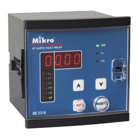
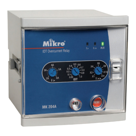
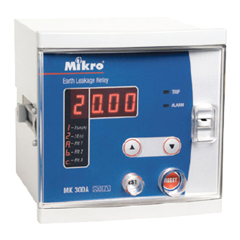
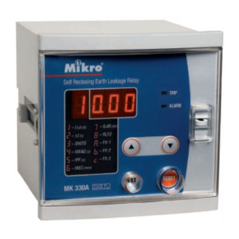
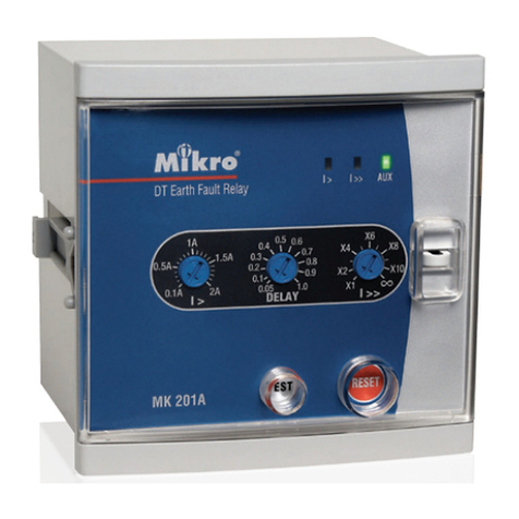
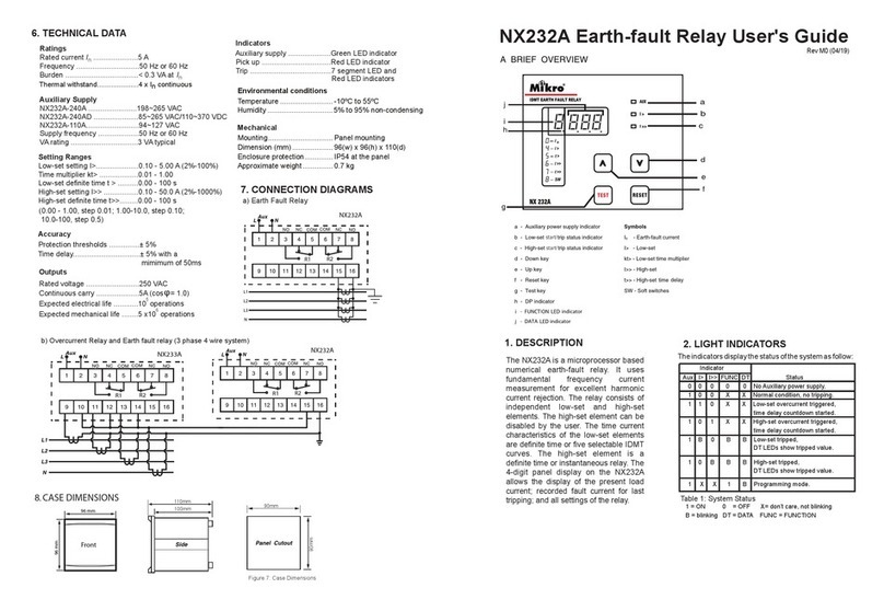
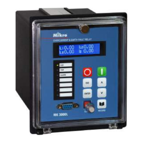
Mikro MK2000 User manual

MK2000
User’s Manual
Features
Multifunction numerical relay
Programmable control outputs
Metering
Fault value recording
MIKRO
Combined Overcurrent and Earth-Fault Relay

MK2000
Page1
Table of Contents Page
1.Introduction 2
2.Description ofoperation 3
3.Characteristic curves 13
4.Soft Switches 18
5.Connection Diagram& TerminalConnection 30
6.Case Dimensions 34
7.Technical Data 35
8.Tests andStandards 37
9.AppendixA 38

MIKRO Page2
The MK2000 combined overcurrent and earth-fault relay is a digital
microprocessor based relay. This relay employs extensive advanced
numerical techniques which are implemented in real time, for the
computation of measured input quantity. Other advanced features
include programmable control output, metering and fault data storage.
A fully digital user interface with bright seven-segment display provides a
very user-friendly access to all the relay settings, meters and fault data.
1. Introduction

2. Description of Operation
The MK2000 relay provides three independent phase overcurrent elements
and one non-directional earth-fault element. All these elements are connected
to the current transformers of the feeder to be protected.
2.1 Phase Overcurrent Protection
When the phase current exceeds the low-set I> setting value, the overcurrent
low-set element starts and delivers a start signal to the display panel and a
group of pre-assigned relay outputs. After a delay time, determined by the
inverse time current characteristic curve selected and measured current, this
overcurrent element operates and delivers a trip signal to the display panel
and a group of relay outputs that are configured to link to the low-set phase
overcurrent tripping.
When the phase current exceeds the high-set I>> setting value, the
overcurrent high-set element starts and delivers a start signal to the display
panel and a group of pre-assigned relay outputs. After a pre-set time,
determined by t>>, this overcurrent element operates and delivers a trip
signal to the display panel and a group of relay outputs that are configured to
link to high-set phase overcurrent tripping.
2.2 Earth-Fault Protection
When the earth-fault current exceeds the low-set IO> setting value, the earth-
fault low-set element starts and delivers a start signal to the display panel
and a group of pre-assigned relay outputs. After a delay time, determined by
the inverse time current characteristic curve selected and measured current,
this earth-fault element operates and delivers a trip signal to the display
panel and a group of relay outputs that are configured to link to the low-set
earth-fault tripping.
When the earth-fault current exceeds the high-set I
O>> setting value, the
earth-fault high-set element starts and delivers a start signal display panel
and a group of pre-assigned relay outputs. After a pre-set time, determined by
tO>>, this earth-fault element operates and delivers a trip signal to the display
panel and a group of relay outputs that are configured to link to high-set
earth-fault tripping.
MK2000
Page3

2.3 Measuring Elements
All the three overcurrent elements and one earth-fault element are provided
with user configurable 1A or 5A current transformer inputs. The MK2000
settings are normalized to 1A. If 5A current transformers are used, the user is
required to connect the current transformers to the 5A block terminal inputs
and normalize all required setting values to 1A before entering it into the
relay.
For each measuring elements, there is one independent high-set and one
independent low-set. The elements' overcurrent or earth-fault low-set tripping
time current characteristics are selectable between inverse definite minimum
time (IDMT) normal inverse curve, long time inverse curve, very inverse curve
and extremely inverse curve. The overcurrent elements and earth-fault
element tripping time current characteristic curves are individually selectable.
The high-set tripping characteristic for both overcurrent element and earth-
fault element are of the definite time type. Instantaneous tripping is made
possible by setting the time to minimum.
2.4 Digital Inputs
The functions of this external binary inputs are
•Blocking the operation of one or more protection stages.
•Resetting a latched output relay in the manual reset mode.
The input can be both ac or dc source. For dc input, the positive (+) terminal is
34 and the negative (-) terminal is 35.
MIKRO Page4

OutputOutput Selectable FunctionSelectable Function
TS1
START1
•Linked to low-set overcurrent and/or earth-fault trip signal.
•Linked to low-set overcurrent and/or earth-fault start signal.
•Linked to high-set overcurrent and/or earth-fault trip signal.
•Linked to high-set overcurrent and/or earth-fault start signal.
•Backup for circuit breaker failure protection.
TS2
TRIP
•Linked to low-set overcurrent and/or earth-fault trip signal.
•Linked to high-set overcurrent and/or earth–fault trip signal.
This is the default trip signal output for both overcurrent and earth-
fault.
SS1
START2 •Linked to low-set overcurrent and/or earth-fault start signal.
•Linked to high-set overcurrent and/or earth-fault start signal.
SS2
SIGNAL1 •Linked to low-set overcurrent and/or earth-fault trip signal.
•Linked to high-set overcurrent and/or earth-fault trip signal.
SS3
SIGNAL2 •Linked to low-set overcurrent and/or earth-fault trip signal.
•Linked to high-set overcurrent and/or earth-fault trip signal.
2.5 Output Contacts
The MK2000 has six relay outputs, namely, TRIP(TS2), START1(TS1), START2
(SS1), SIGNAL1(SS2), SIGNAL2(SS3) and IRF. The functions of the relay
outputs are user programmable as follow:
IRF relay is not user programmable. The function of this relay is for signaling
an internal relay failure. When the auxiliary power of the relay is switched on
and the MK2000 is functioning normally, the IRF relay output will be
energized hence the NC contact will open and the NO contact will close.
MK2000
Page5

i)
This light indicates the presence of auxiliary power supply.
ii)
This light indicates the relay is in start or trip condition. [Refer to section xv.
(page 9) on trip status display].
2.6 Display
MIKRO Page6

iii)
The 3-digit display indicates the value of the item selected.
iv)
If any of the above light is on, the relay is in metering mode. The 3-digit
display indicates the corresponding phase current or earth-fault current.
v)
When this indicator is lighted, the 3-digit display simultaneously indicates the
overcurrent low-set current setting.
vi)
When this indicator is lighted, the 3-digit display simultaneously indicates the
overcurrent time multiplier setting.
vii)
When this indicator is lighted, the 3-digit display simultaneously indicates the
overcurrent high-set current setting.
viii)
When this indicator is lighted, the 3-digit display simultaneously indicates the
overcurrent high-set delay time setting.
MK2000
Page7

ix)
When this indicator is lighted, the 3-digit display simultaneously indicates
the earth-fault low-set current setting.
x)
When this indicator is lighted, the 3-digit display simultaneously indicates
the earth-fault time multiplier setting.
xi)
When this indicator is lighted, the 3-digit display simultaneously indicates
the earth-fault high-set current setting.
xii)
When this indicator is lighted, the 3-digit display simultaneously indicates
the earth-fault high-set delay time setting.
xiii)
When this light is on, the relay is in software switch setting mode. The 3-digit
display indicates the soft switch number and the switch setting.
xiv)
When this light is on, one of the indicators IL1, IL2, IL3 or Iowill switch on
simultaneously. The 3-digit display then indicates the stored value of the
corresponding phase or earth-fault current during the previous tripping of
the relay.
Note that the fault values recorded are at the moment of tripping.
SWITCH
NUMBER SWITCH
VALUE
MIKRO Page8

xv) Start and trip status display
a) Normal condition
Under normal operating condition, all the light indicators are switched
off except the AUX indicator. If the RESET/STEP key is pressed, the
corresponding indicator and the 3-digit display will light up. After 6
minutes, the indicator and the 3-digit display will automatically switch
off if no further key is pressed.
b) Relay start condition
When the overcurrent elements or the earth-fault element measure an
input current higher than the set value, the relay starts and the START
indicator light up. If the measured current subsequently drops below
the set value before reaching trip condition, the START indicator will
switch off.
c) Relay trip condition
MK2000
Page9
One of these indicators blinks to indicate the
source of tripping.
One of these indicators blinks to indicate high-
set or low-set tripping element.
The 3-digit display indicates the tripping value
Under relay trip condition, the START/TRIP
indicator lights up until the relay is reset.

2.7 Key Button Input
i). RESET/STEP key
There are two functions associated with this key.
•Reset the system when in trip mode.
•Scroll the display to view the measured current, recorded fault current and
the relay current setting and time setting.
The scrolling sequence is as follow:
IL1
IL2
IL3
IO
IL1 Data
IL2 Data
IL3 Data
IOData
IO>/In
KtO>
IO>>/In
tO>>
I>/In
Kt>
I>>/In
t>>
START
MIKRO Page10

MK2000
Page11
ii) The PROGRAM key
Pressing this key once to enter into programming mode for the selected
items (e.g. I/In). The light indicator for the selected item blinks to indicate
that the relay is in programming mode. By pressing this PROGRAM key
again while in the programming mode, the new value of the selected item is
saved, the relay then exits from programming mode and the light indicator
for the selected item stop blinking.
iii) The UP and DOWN keys
These keys are for changing the value of the selected item while in
programming mode.
iV) The SWITCH key
Press this key to scroll through all the software switches.

2.8 Key Operation of Setting
i) To program the settings for I>/In, kt>, I>>/In, t>>, Io>/In, kto>, Io>>/In and
to>>.
Step 1
Select the required item by stepping through all the items using the RESET/
STEP key. The corresponding light of the selected item will be lighted.
Step 2
Press the PROGRAM key once, the indicator light of the selected item will
blink to indicate that the system is now in programming mode.
Step 3
Use the UP or DOWN key to select the desired value. Holding down the key
until the desired value appears.
Step 4
To save the selected value, press the PROGRAM key once. The indicator
light stop blinking and the setting is saved.
To abort without saving the selected setting, press the RESET/STEP key.
ii) To program the software switch setting
Step 1
Press the SWITCH key until the desired switch number appears on the
display.
Step 2
Press the PROGRAM key to enter into programming mode. The SWITCH light
will blink to indicate that the system is in switch programming mode.
Step 3
Use the UP or DOWM key for changing the soft switch setting.
Step 4
To save the change, press the PROGRAM key again until SWITCH light stop
blinking .
To abort the change, press the SWITCH key or RESET/STEP key.
MIKRO Page12

Both the low-set overcurrent and earth-fault elements can be independently
configured to have following IDMT characteristic curves :-
•Normal inverse
•Very inverse
•Extremely inverse
•Long-time inverse
The relationship between current and time for the above curves comply with the
standard IEC255-4 and may generally be expressed as :
___kβ__
( I/I>)α-1
Where t = operating time in seconds
k = time multiplier
I = measured current
I> = set current
α= constant
β= constant
Both the high-set overcurrent and high-set earth-fault elements are
independently configured with definite time delay only. The time delay can be
from 0.05 sec (instantaneous) to 300 sec. The high-set feature can also be
disabled by the user.
MK2000
Page13
3. Characteristic Curves
Characteristic curveCharacteristic curve αβ
Normal Inverse 0.02 0.14
Very Inverse 1.0 13.5
Extremely Inverse 2.0 80.0
Long-time Inverse 1.0 120.0
t =

MIKRO Page14
NORMAL INVERSE
1 10
0.1
1
10
0.05
0.1
0.2
0.3
0.4
0.5
0.6
0.7
0.8
0.9
1.0
20
k
t/s
I/I>

MK2000
Page15
VERY INVERSE
1 10
0.01
0.1
1
10
0.05
0.1
0.2
0.3
0.4
0.5
0.6
0.8
1.0
20
k
t/s
I/I>

MIKRO Page16
EXTREMELY INVERSE
1 10
0.01
0.1
1
10
100
0.05 0.1 0.2
0.3
0.4
0.5
0.6
0.8
1.0
20
k
t/s
I/I>

MK2000
Page17
LONG-TIME INVERSE
1 10
0.1
1
10
100
0.05
0.1
0.2
0.3
0.4
0.5
0.6
0.8
1.0
20
200
k
t/s
I/I>

These soft switches are for configuring and testing of the MK2000 relay. The
functions for all these switches are listed below. Please note that the switch
settings are in hexadecimal format.
4.1 Switch Group 1
This switch allows the user to activate the relay output one-by-one. Once
entered into the switch programming mode, the output can be switched on by
using the UP and DOWN key.
MIKRO Page18
4. Soft Switches
Switch ValueSwitch Value FunctionFunction
00 All relays de-activated
01 Only TS1 activated (START1)
02 Only TS2 activated (TRIP)
03 Only SS1 activated (START2)
04 Only SS2 activated (SIGNAL1)
05 Only SS3 activated (SIGNAL2)

4.2 Switch Group 2
This switch configures the blocking signal and high-set elements selection.
BLOLBLOL -Block Low-set Overcurrent
This switch enables or disables the low-set overcurrent blocking function by the
digital input signal.
1 = I> stage blocking enabled.
0 = I> stage blocking disabled.
BLOHBLOH -Block High-set Overcurrent
This switch enables or disables the high-set overcurrent blocking function by
the digital input signal.
1 = I>> stage blocking enabled
0 = I>> stage blocking disabled.
BLELBLEL -Block Low-set Earth-Fault
This switch enables or disables the low-set earth-fault blocking function by the
digital input signal.
1 = IO> stage blocking enabled.
0 = IO> stage blocking disabled.
BLEHBLEH -Block High-set Earth-Fault
This switch enables or disables the high-set earth-fault blocking function by the
digital input signal.
1 = IO>> stage blocking enabled.
0 = IO>> stage blocking disabled.
MK2000
Page19
RSVRSV RSVRSV HEESHEES HOESHOES BLEHBLEH BLELBLEL BLOHBLOH BLOLBLOL
Default value 00000000
Default hexadeci-
mal value 00
User setting 00
User hexadecimal
value*
* Refer to Appendix A for the corresponding hexadecimal value.
Table of contents
Other Mikro Relay manuals
