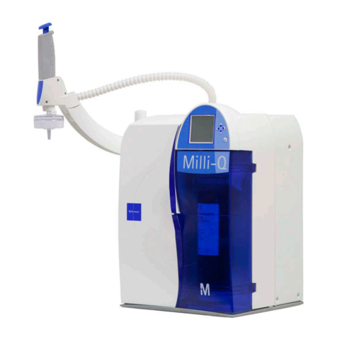
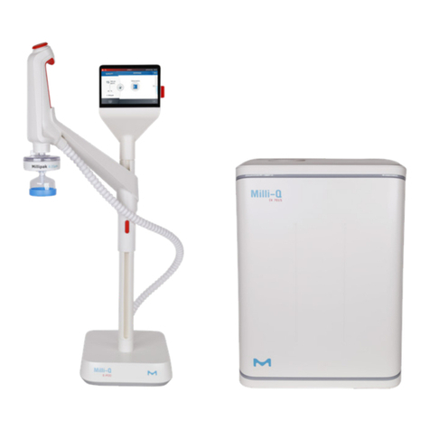
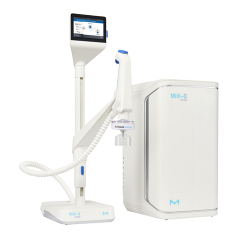
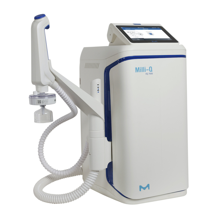
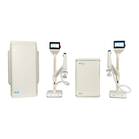
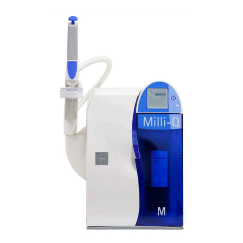
Milli-Q HX Series User manual

Milli-Q® HX 7040-7150 / HR 7060-7220
User Manual


Contents
Legal Information............................................................................................5
Safety Information...........................................................................................6
Recycling.........................................................................................................7
Preface.............................................................................................................8
Specifications..................................................................................................9
Feed Water Specifications..........................................................................................10
Product Water Specifications......................................................................................10
System Dimensions....................................................................................................12
Weight Specifications..................................................................................................13
Electrical Specifications..............................................................................................13
Environmental Specifications......................................................................................14
System Overview.......................................................................................... 15
Operating Principle .................................................................................................... 16
Distribution loop management and configurations......................................................17
System Display..............................................................................................18
How to Navigate Between Overview and Workspace Screens.................................. 18
Overview Screen.........................................................................................................19
How to Change the System from Standby to Ready.................................................. 23
Workspace Screens....................................................................................................25
Glance Workspace.............................................................................................26
Maintenance Workspace................................................................................... 30
Configuration Workspace...................................................................................32
How to View Hidden Applications......................................................................35
Alarms and Alerts - Definition..................................................................................... 36
How to Acknowledge Alarms and Alerts............................................................37
Screensaver................................................................................................................38
Maintenance.................................................................................................. 39
How to Use Maintenance Wizard................................................................................40
RO Cleaning tools.......................................................................................................41
RO Cleaning............................................................................................................... 42
Communication Ports & Software...............................................................43
How to Change the Network Configuration.................................................................44
How to Power On and Power Off the Water System..................................46
How to Use the Distribution Schedule........................................................47
How to Flush the Tank..................................................................................49
Contents | 3

Ordering Information....................................................................................50
Consumable Catalogue Numbers...............................................................................51
Accessory Catalogue Numbers ................................................................................. 52
System Catalogue Numbers.......................................................................................53
Appendix........................................................................................................54
Display Icon Description............................................................................................. 55
System Operating modes........................................................................................... 58
Emergency Procedure in Multi-system configuration..................................................59
4| Contents

Legal Information
Notice
It has always been Millipore S.A.S. policy to continuously improve its products.
The information in this document is subject to change without notice and should not be
construed as a commitment by Millipore S.A.S. Millipore S.A.S. assumes no responsibility
for any errors that might appear in this document. This manual is believed to be complete
and accurate at the time of publication. In no event shall Millipore S.A.S. be liable for
incidental or consequential damages in connection with or arising from the use of this
manual.
We manufacture and sell water purification systems designed to produce pure or ultrapure
water with specific characteristics (µS/cm, °C, TOC, CFU/ml, EU/ml) when it leaves the
water purification system provided that the systems are fed with water quality within
specifications, and properly maintained as recommended by the supplier.
We do not warrant these systems for any specific application. It is up to the end user to
determine if the quality of the water produced by our systems matches his expectations, fits
with norms/legal requirements and to bear responsibility resulting from the usage of the
water.
Product Warranty and limitation of liability
The applicable warranty and limitation of liability for the products listed in this publication
may be found at http://www.merckmillipore.com/ or http://www.emdmillipore.com/ within the
"Conditions of Sale" applicable to your purchase transaction.
Copyright
©2017 MILLIPORE S.A.S. PRINTED IN FRANCE. ALL RIGHTS RESERVED. THIS BOOK
OR PARTS THEREOF MAY NOT BE REPRODUCED IN ANY FORM WITHOUT THE
WRITTEN PERMISSION OF MILLIPORE S.A.S.
The photographs illustrating the products are non-contractual.
Trademarks
Elix and Progard are registred trademarks of Merck KGaA, Darmstadt, Germany.
The " M " logo is registered trademark of Merck KGaA, Darmstadt, Germany.
All other trademarks are trademarks of their respective manufacturers.
Document Reference: USER-LRG2-ELIX-EN
Revision: V4.0
Legal Information | 5

Safety Information
Symbol What it means
This UV RADIATION sticker is used to refer to a position on the system cabinet
or inside of it where exposure to UV light is possible.
This HAZARD sticker is used to refer to a position on the system cabinet or
inside of it that could be hazardous.
This ELECTRICAL GROUND sticker is used to refer to a position on the
system cabinet or inside where an electrical ground connection is made.
This ELECTRICAL HAZARD sticker is used to refer to a position on the system
cabinet or inside where an electrical danger could exist.
This HOT SURFACE sticker is used to refer to a position on the system cabinet
or inside where a hot surface could exist.
• The System must be connected to a source of electrical power that is
earth grounded.
• Only an authorized person following the local safety regulations can work
on this equipment.
• Unplug the electrical power cord before plugging in or removing any
components on the electronic board(s).
6| Safety Information

Recycling
Directive 2002/96 EC: For European users only.
The symbol "crossed bin" on a product or its packaging
indicates that the product should not be treated like
household waste when discarded. Instead, the product
should be disposed of at a location that handles discarded
electric or electronic equipment.
Proper disposal of equipment containing electric or
electronic components will help to reduce pollution effects to
the environment or to human health. Proper recycling of
these products helps in environmental preservation and
helps to protect natural resources. For more information
about recycling of products containing electric or electronic
components, please contact your local recycling
representative or organization.
Recycling | 7

Preface
Thank you for purchasing our water purification system.
For correct operation, read and fully understand the contents of this user manual before
attempting to use the system. It is recommended to store this user manual in a safe and
convenient place where it can be easily referred to when required.
This user manual is intended for use with a Milli-Q®HX 7040-7150 - HR 7060-7220 water
purification system.
The word "system" is used to refer to Milli-Q®HX 7040-7150 - HR 7060-7220 unless
specified otherwise in the text.
The abbreviations "LC" and "HC" used after HX 7040-7080 and HR 7060-7120 refer to
systems for Low Chlorine and High Chlorine feed water.
The words "display" or "MMI" (Man-Machine Interface) are used to refer to the user
interface in this document.
The words "master" and "slave" have been replaced respectively by "primary" and
"auxiliary" for systems with software package >35.
Depending on the system type and options that are purchased, some of the features
described may not apply to the system you are using.
For any questions or requests, please contact your Sales Specialist or Qualified Service
Representative.
8| Preface

Specifications
Specifications | 9

Feed Water Specifications
The system has been designed to operate within feed water specifications:
Parameter Value or range (HX and HR Systems)
Pressure 2 – 6 bar
Flow rate > 10 L/min @ 2 bar
Feed water type Potable water
Temperature 5 – 35° C
Conductivity 10 – 2000 µS/cm @ 25° C
pH 4 - 10
Hardness (as CaCO3) < 300 ppm
Silica concentration < 30 ppm
Carbon Dioxide concentration (CO2) < 30 ppm
Langelier Saturation Index (LSI) < 0.3
Fouling Index (FI5) or Silt Density Index
(SDI) ≤ 7 (*)
Total Organic Carbon (TOC) ≤ 1 ppm
Free chlorine for LC systems < 1.5 ppm
Free chlorine for HC systems 1.5 ppm - 3 ppm
* < 12 when the optional UF pretreatment unit is installed.
Product Water Specifications
The system has been designed to produce water according to specifications when
operating within Feed Water Specifications.
Parameter HX Systems: Value or
range HR Systems: Value or
range
Resistivity > 5 MΩ.cm @ 25°C NA
Conductivity < 0.2 µS/cm @ 25 °C 95% ionic rejection (99%
Particulates rejection)
Total Organic Carbon (TOC) < 30 ppb 99% organic rejection for
MW>200 Dalton
Bacteria < 10 CFU/mL NA
Silica <3ppb ( rejection > 99,9% ) NA
10 | Specifications

Applicable standards TO HX system:
The system has been designed to be compliant with water quality standards in the
laboratory.
The system produces water that meets the following requirements:
• ISO 3696: 1996 Grade 2 Water for Analytical laboratory use
• GB/T6682-2008 Grade 2 Water for Analytical laboratory use
• ASTM D1193 type 2 (2006 Reapproved 2011) Reagent Grade Water
• Japanese Industrial Standard JIS K 0557, A3 – 2008
•European Pharmacopeia Purified water 8.0
• United States Pharmacopeia Purified water (USP37)
• Chinese Pharmacopeia (2010 appendix XVII A-227) Water for Pharmaceutical Purposes
• Japanese Pharmacopeia (17-2016) Purified Water
Specifications | 11

System Dimensions
HX and HR System dimensions:
12 | Specifications

Weight Specifications
The location where the Water Purification System is installed will need to fully support its
Operating Weight:
System type Dry weight (Kg/Lb) Shipping weight (Kg/Lb)
Milli-Q®HX 7040 78 / 172 97 / 213
Milli-Q®HX 7080 86 / 190 105 / 231
Milli-Q®HX 7120 94 / 208 113 / 249
Milli-Q®HX 7150 105 / 232 124 / 273
Milli-Q®HR 7060 72 / 166 91 / 207
Milli-Q®HR 7120 75 / 179 94 / 220
Milli-Q®HR 7170 78 / 192 97 / 233
Milli-Q®HR 7220 84 / 221 103 / 252
Shipping Weight is defined as a dry system in its shipping container. It does not include
the consumable or any accessories.
Dry Weight is defined as a system without its shipping container. It does not include the
consumable or any accessories.
The UF pre filtration option weight is 22 kg / 121.3 lb
Electrical Specifications
The systems can be supplied by Mains electricity 90-253 VAC with a frequency range from
48 to 62Hz.
System type Voltage Power Consumption (VA)
Milli-Q®HX 7040/7080 220-240 VAC @ 50/60 Hz 750
Milli-Q®HX 7120/7150 220-240 VAC @ 50/60 Hz 870
Milli-Q®HX 7040/7080 120 VAC @ 60 Hz 775
Milli-Q®HX 7120/7150 120 VAC @ 60 Hz 900
Milli-Q®HX 7040/7080 100 VAC @ 50/60 Hz 775
Milli-Q®HX 7120/7150 100 VAC @ 50/60 Hz 900
Milli-Q®HR 7060/7120 220-240 VAC @ 50/60 Hz 620
Milli-Q®HR 7170/7220 220-240 VAC @ 50/60 Hz 750
Milli-Q®HR 7060/7120 120 VAC @ 60 Hz 620
Milli-Q®HR 7170/7220 120 VAC @ 60 Hz 750
Milli-Q®HR 7060/7120 100 VAC @ 50/60 Hz 620
Milli-Q®HR7170/7220 100 VAC @ 50/60 Hz 750
The source of electrical power must be earth grounded.
Specifications | 13

Environmental Specifications
Environmental specifications have been defined for normal system operation.
Altitude ≤ 2000 m
Ambient operating temperature 10 – 40 °C
Relative humidity 80% up to 31°C (decreasing linearly to 50 %
relative humidity at 40 °C)
Ambient storage temperature 0 – 40 °C
Ambient storage humidity 10 – 95 %
Installation category I
Pollution degree 2
Noise level < 50 db at 1 meter
For indoor use only
14 | Specifications

System Overview
System, components and connections.
1. Display 12. DRP port (Data report: 2 Alarm output and 2
measure output)
2. System name 13. External solenoid valve port
3. USB port 14. Ethernet port
4. Matrix code (containing system serial number and
type) 15. System type identification label
5. Progard®pack(s) 16. Inlet connector (3/4" BSP)
6. Wheel locking nut 17. Outlet connector (3/4" Tri-Clamp)
7. Securing bracket 18. External pretreatment port
8. Water system backpanel 19. Leak detector port
9. Waste outlet 20. Tank monitoring port (Tank level, overflow)
10. Power Entry (Mains) & switch 21. Device control port (ASM, UV lamp)
11. C2 Out port (Distribution interfaces)
Note: The system covers can be cleaned or disinfected by using alcohol (Ethanol
and Isopropanol).
System Overview | 15

Operating Principle
The Elix water system is designed to produce Type 2 water to feed a SDS 500 reservoir or
a custom tank and to manage a distribution loop and accessories when installed. The
system can be installed in a single or multi-system configuration.
• The water system purifies tap water using a Progard®Pack(s) and Reverse Osmosis
followed by Elix®Technology. This process is called Makeup (I).
• The purified water is then stored in a tank (SDS 500 or custom tank). This is referred to
as Storage (II).
•The stored water can be distributed to a loop . This process is called Distribution (III).
HX 7040 flow schematic:
HR 7060 flow schematic:
This view and more information about components can be retrieved using the Flow
Schematic application at
(Glance Workspace > Flow Schematic)
The volume of water in the Tank controls Makeup water production.
The storage part of the system is passive. The volume of water in the tank is a function of
both the Makeup and Distribution processes.
Ready mode is used to get the processes operating.
Standby mode is used to stop the corresponding process in the event of a leak or
maintenance purpose.
System operating modes are listed in the Appendix.
The Makeup and Distribution are two independent processes. When one of the processes
is in standby, alarm stop or maintenance it will not stop the other process from working.
16 | System Overview

Distribution loop management and configurations
A system can be installed as a single system or as part of a multi-system configuration. If
installed, a system can manage a distribution loop and its accessories.
System not managing a distribution loop
When the system does not manage a distribution loop, the system needs to get information
from the external sensors as the system needs to stop in certain conditions, for example if
an external tank is full or in the case of water detected. The following signals are taken into
account by the system:
• Tank level
• Water Sensor
• Overflow
System in a single-system configuration managing a distribution loop
The system is connected to the external sensors and actuators linked to the distribution
loop:
• The pump in simplex or duplex mode
• Tank level mangement
• The ASM
• UV lamp
• Dumping valve
•Leak detection
• Overflow
System in a multi-system configuration
In a multi-system configuration, the systems are connected together in order to share the
same information (For example: tank level sensor information, or a water detection alarm
that will stop all systems) and to synchronize the production processes.
In this configuration, one system is called the “Primary” and the other system(s) is/are
called the “auxiliary(s)”. A maximum of 3 systems can be installed in this way.
The connections related to the distribution are connected to the primary system. In this
configuration the primary system manages the distribution loop and the related consumable
lifetimes.
System Overview | 17

System Display
The main display on the system is a touchscreen. Tapping display button icons moves the
display between screens and launches applications.
The Overview screen is the main screen. The Workspace screens ( Glance, Maintenance
and Configuration) contain the system applications.
How to Navigate Between Overview and Workspace Screens
Procedure
•Navigation between the Overview screen and the Workspace screens is done using
the display icon buttons on the bottom right of the screens.
•From Overview when tapping the arrow icon , Glance Workspace is always the first
screen opened.
•The return to Overview can be made from any of the three Workspace screens by
using the Exit icon .
18 | System Display

Overview Screen
The Overview screen is the default view on the system display. It is divided into 3 sections
and each section represents one of the 3 parts of the water system.
Figure 1: Overview Screen
(1): Makeup - information on Makeup process
(2): Storage - information on Storage portion
(3): Distribution - information on Distribution process
(A): Top banner - System Information
A1: Screen Identifier - Overview
A3: Connectivity (external interfaces: Ethernet and USB)
(B): Water System Process Identifier and Operating Mode
B1: Makeup process is in READY mode.
B3: Distribution process is in RECIRCULATION mode. The Distribution process can also
be NOT ACTIVE or in MULTI-SYSTEM auxiliary mode.
The system operating modes are described in the appendix.
(C): Measure Widgets (measure widgets are blue when the process is active or grey if it is
not active)
C1: Measures from the Makeup process
1 Bar graph showing water quality in MΩ.cm @ 25°C and the
alarm setpoint (black triangle). Available only on HX systems.
2Displays Makeup water quality in a user defined unit. TC is
displayed when Temperature Compensation (TC) mode is on.
On HR systems, the unit is µS.
If the water quality measured is under the setpoint, this value
blinks between blue and red.
3Displays Makeup water temperature in a user defined unit.
System Display | 19

C2: Measures from the Storage process
1 Bar graph showing tank level in %.
• Top arrow indicates Tank Filling Restart setpoint
•Bottom arrow indicates TANK EMPTY alarm setpoint
2Displays volume of water in the Tank in a user defined unit.
3Displays tank level in %.
C3: Distribution process.
The distribution can be in the following modes:
Distribution in Forced mode:
Distribution process is forced to ON. Distribution loop in this
mode is always recirculating.
Note: This function can be used to refresh the water from
the distribution loop, for example after a loop sanitization
or prior a sampling procedure use.
Distribution in Scheduled mode:
The Distribution is activated based on defined schedule.
Note: It is recommended to activate this mode for normal
use of the system and distribution loop.
Distribution in Auto-recirculation mode:
An automatic recirculation occurs once every hour (15 to 60
min/h depending on the software configuration).
Note: It is recommended to activate this mode when the
System and distribution loop are not used for a period of
time.
Distribution is Inactive :
The system is not managing a distribution loop or the
distribution loop is managed by a primary.
20 | System Display
This manual suits for next models
9
Table of contents
Other Milli-Q Water Filtration System manuals
Popular Water Filtration System manuals by other brands

BioQuest
BioQuest BIO2 201-PS-C Operator's manual

Franke
Franke FilterFlow mini Installation guide & technical information

NKT Photonics
NKT Photonics SuperK VARIA Product guide

Premier
Premier Whole House Filtration 500221 Installation, operation and maintenance manual

velda
velda FLOATING COMBI FILTER User instructions

Nikken
Nikken PiMag Aqua Pour deluxe operating manual