miniDSP NANOSHARC User manual

miniDSP Ltd, Hong Kong / www.minidsp.com / Features and specifications subject to change without prior notice 3
CONTENTS
Important Information ...............................................................................................................................................4
System Requirements.............................................................................................................................................4
Disclaimer/Warning................................................................................................................................................4
Warranty Terms......................................................................................................................................................5
FCC Class B Statement ............................................................................................................................................5
CE Mark Statement.................................................................................................................................................5
A note on this manual ............................................................................................................................................5
1 Product Overview ................................................................................................................................................6
1.1 The miniDSP concept..................................................................................................................................6
1.2 Choosing a plugin .......................................................................................................................................7
1.3 Ordering plugins .........................................................................................................................................7
2 Board Layout and Connectivity............................................................................................................................8
2.1 Board layout ...............................................................................................................................................8
2.2 DC power ....................................................................................................................................................8
2.3 USB connectivity.........................................................................................................................................9
2.4 Optical digital audio input ..........................................................................................................................9
2.5 I2S expansion header pinouts ....................................................................................................................9
2.6 I2S overview ...............................................................................................................................................9
2.7 I2S details................................................................................................................................................. 10
2.8 Additional I2S usage notes ...................................................................................................................... 11
3 USB Audio ......................................................................................................................................................... 12
3.1 Mac OS X.................................................................................................................................................. 12
3.2 Windows.................................................................................................................................................. 13
3.2.1 Driver installation ............................................................................................................................ 13
3.2.2 Configuration................................................................................................................................... 13
4 Infrared remote control.................................................................................................................................... 14
5 Additional information...................................................................................................................................... 15
5.1 Specifications........................................................................................................................................... 15
5.2 MCU firmware update............................................................................................................................. 16
5.3 Troubleshooting ...................................................................................................................................... 17
5.4 Obtaining support.................................................................................................................................... 17

miniDSP Ltd, Hong Kong / www.minidsp.com / Features and specifications subject to change without prior notice 4
IMPORTANT INFORMATION
Please read the following information before use. In case of any questions, please contact miniDSP via the
support portal at minidsp.desk.com.
SYSTEM REQUIREMENTS
To configure the miniDSP audio processor, you will require a Windows PC or Apple Mac OS X computer with the
following minimum specification:
Windows
•PC with 1GHz or higher processor clock speed. Intel® Pentium®/Celeron® family, or AMD K6®/AMD
Athlon®/AMD Duron® family, or compatible processor recommended.
•512 megabytes (MB) of RAM or higher
•Keyboard and mouse or compatible pointing device
•USB 2.0 port
•Microsoft• ® Windows® Vista® SP1/ XP pro SP2/Win7/Win8.1/Win10
•Microsoft• ® .NET framework v3.5 or later
•Adobe AIR environment (latest version)
•Adobe Flash player (latest version)
Mac OS X
•Intel-based Mac with 1 GHz or higher processor clock speed
•512 megabytes (MB) of RAM or higher
•Keyboard and mouse or compatible pointing device
•USB 2.0 port
•Mac OS X 10.8 or higher
•Adobe AIR environment (latest version)
•Adobe Flash player (latest version)
DISCLAIMER/WARNING
miniDSP cannot be held responsible for any damage that may result from the improper use of this product or
incorrect configuration of its settings. As with any other product, we recommend that you carefully read this
manual and other technical notes to ensure that you fully understand how to operate this product. The miniDSP
audio processor is a powerful tool, and misuse or misconfiguration, such as incorrectly set gains or excessive
boost, can produce signals that may damage your audio system.
As a general guideline, you should perform the initial configuration of the miniDSP audio processor before
enabling audio through any connected output device or amplification. Doing so will help ensure that the
software is correctly configured.

miniDSP Ltd, Hong Kong / www.minidsp.com / Features and specifications subject to change without prior notice 5
Finally, note that the miniDSP audio processor is a very flexible device, and many of the questions we receive at
the tech support department are already answered in this user manual and in the online application notes on
the miniDSP.com website. So please take the time to carefully read this user manual and the online technical
support. Thanks for your understanding!
WARRANTY TERMS
miniDSP Ltd warrants this product to be free from defects in materials and workmanship for a period of one
year from the invoice date. Our warranty does not cover failure of the product due to incorrect connection or
installation, improper or undocumented use, unauthorized servicing, modification or alteration of the unit in any
way, or any usage outside of that recommended in this manual. If in doubt, contact miniDSP prior to use.
FCC CLASS BSTATEMENT
This device complies with Part 15 of the FCC Rules. Operation is subject to the following two conditions:
•This device may not cause harmful interference.
•This device must accept any interference received, including interference that may cause undesired
operation.
Warning: This equipment has been tested and found to comply with the limits for a Class B digital device,
pursuant to Part 15 of the FCC Rules. These limits are designed to provide reasonable protection. This
equipment generates, uses and can radiate radio frequency energy and, if not installed and used in accordance
with the instructions, may cause interference to radio communications. However, there is no guarantee that
interference will not occur in a particular installation. If this equipment does cause harmful interference to radio
or television reception, which can be determined by turning the equipment off and on, the user is encouraged to
try to correct the interference by one or more of the following measures:
•Reorient or relocate the receiving antenna.
•Increase the separation between the equipment and receiver.
•Connect the equipment into an outlet on a circuit different from that to which the receiver is connected.
•Consult the dealer or an experienced radio/TV technician for help.
Notice: Shielded interface cable must be used in order to comply with emission limits.
Notice: Changes or modification not expressly approved by the party responsible for compliance could void the
user’s authority to operate the equipment.
CE MARK STATEMENT
The nanoSHARC has passed the test performed according to European Standard EN 55022 Class B.
ANOTE ON THIS MANUAL
This User Manual is designed for reading in both print and on the computer. If printing the manual, please print
double-sided. The embedded page size is 8 ½” x 11”. Printing on A4 paper will result in a slightly reduced size.

miniDSP Ltd, Hong Kong / www.minidsp.com / Features and specifications subject to change without prior notice 6
1PRODUCT OVERVIEW
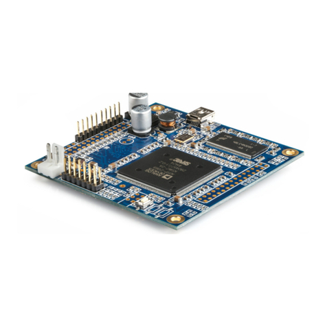
Thank you for choosing the nanoSHARC audio processor board. The nanoSHARC is a tiny yet extremely powerful
and flexible digital audio processing circuit board intended for OEM applications and advanced DIY enthusiasts.
It includes an onboard optical digital input and asynchronous USB audio input. Audio output and additional
audio inputs are to be provided by the system integrator via I2S interfaces.
The audio processing functionality of the board is implemented via the use of a software plugin. For more
information on available plugins, see Choosing a plugin on page 7.
The nanoSHARC is an evolution of miniDSP’s existing audio processing solutions. For those seeking a ready-made
“in the box” solution with similar capabilities, please see our 2x4 HD, DDRC-24, and other products.
1.1 THE MINIDSP CONCEPT
The miniDSP concept is “one hardware unit + one software plugin = audio processing solution.” This concept
leverages the inherent flexibility of DSP (digital signal processing) to deliver a range of flexible but cost-effective
solutions.
Hardware unit
In this case, the hardware unit is the miniDSP nanoSHARC board.
Software plugin
The software plugin is installed on your PC or Mac, and determines the processing that the DSP
will perform. It provides a friendly user interface, and downloads instructions into the miniDSP
hardware unit that tell it how to process the audio signal. See Choosing a plugin on page 7for
more information on plugins.

miniDSP Ltd, Hong Kong / www.minidsp.com / Features and specifications subject to change without prior notice 7
1.2 CHOOSING A PLUGIN
Currently, a single plugin is available for the nanoSHARC board. Its key features are summarized below. (This
table will be expanded when future plugins become available.)
Table 1. nanoSHARC plugins
2x4 HD1
DDRC-24 plugin
Internal sample rate
96 kHz
48kHz
Number of input channels
2
2
Number of output channels
4
4
Access to I2S input1
✓
✓
Access to I2S output1
✓
✓
Number of FIR taps (total)
4096
N/A
Minimum FIR taps per channel
6
N/A
Maximum FIR taps per channel
2048
N/A
PEQ bands per input channel
10
N/A
PEQ bands per output channel
10
10
Crossover
LPF&HPF up to
48db
LPF&HPF up to
48db
Compressor block
✓
✓
Max per-channel time delay
80 ms
30 ms
1. Requires suitable hardware/interface circuitry.
For detailed information on the 2x4 HD1 plugin, see Sections 3.1 and 5 of the miniDSP 2x4 HD User Manual.
For detailed information on the DDRC-24 plugin, please see the miniDSP DDRC-24 User Manual.
1.3 ORDERING PLUGINS
Plugins must be ordered in addition to the hardware:
•2x4 HD1 plugin
•DDRC-24 plugin

miniDSP Ltd, Hong Kong / www.minidsp.com / Features and specifications subject to change without prior notice 8
2BOARD LAYOUT AND CONNECTIVITY
This section describes the board and its interfaces.
2.1 BOARD LAYOUT
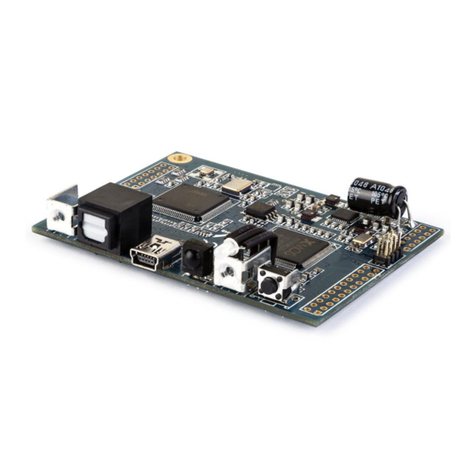
This diagram shows the layout of the nanoSHARC board.
2.2 DC POWER
Provide DC power between pins 9 and 10 (ground) and pins 11 and
12 (12 V DC) of header J2. The supply voltage must be 12V DC, or the
board may malfunction or be damaged. We strongly caution users to
double check their power supply before connecting it to the board.
A polarized molex connector (2.54mm pitch as shown on picture) can
be pre-installed on request to easily connect to a panel mount
2.1mm DC barrel connector.

miniDSP Ltd, Hong Kong / www.minidsp.com / Features and specifications subject to change without prior notice 9
2.3 USB CONNECTIVITY
Connect mini USB port (mini type B) to a computer to configure the board. The USB port also provides
asynchronous USB Audio (Class 2) streaming at all standard sample rates from 44.1 to 192 kHz (see Section 3).
USB Audio input is selected from within the plugin or via remote control.
2.4 OPTICAL DIGITAL AUDIO INPUT
Connect the optical port to a digital source. Thanks to the onboard ASRC (asynchronous sample rate convertor),
sample rates from 20 to 216 kHz are accepted. Optical digital audio input is selected from within the plugin or
via remote control.
2.5 I2S EXPANSION HEADER PINOUTS
Headers J2 and J5 are provided for connection of I/O circuitry via I2S. The pinouts are shown in Table 2 and
Table 3. Note that I2C_SCL and I2C_SDA are intended for miniDSP use only – they are not documented or
supported for other use.
Table 2. J2 expansion header pinout
Pin
Function
Pin
Function
1
I2S_LRCLK
2
I2S_BCLK
3
GND
4
MCLK
5
I2S_OUT0
6
I2S_OUT1
7
I2C_SCL
8
I2C_SDA
9
GND
10
GND
11
+12V
12
+12V
Table 3. J5 expansion header pinout
Pin
Function
Pin
Function
1
I2S_LRCLK
2
I2S_BCLK
3
GND
4
MCLK
5
I2S_OUT0
6
I2S_OUT1
7
I2S_OUT2
6
I2S_OUT3
9
GND
10
GND
11
I2S_IN0
12
I2S_IN1
13
I2S_IN2
14
I2S_IN3
2.6 I2S OVERVIEW
I2S, or Inter IC Sound, is an electrical serial bus used to interface digital audio devices at the chip and circuit
board level. An I2S interface consists of up to three clocks, and a data line for each pair of channels. There are
three types of clock:

miniDSP Ltd, Hong Kong / www.minidsp.com / Features and specifications subject to change without prior notice 10
MCLK The master clock that the nanoSHARC uses internally. This clock is always provided as an output
by the nanoSHARC, and connected circuitry can choose whether or not to use it.
LRCLK The frame synchronization clock, also known as the word clock. This clock is equal to the
sampling frequency (Fs) of the audio signal.
BCLK The bit clock (also known as shift clock or system clock). This is always equal to 64 x Fs.
Table 4 summarizes the relation between the clocks for the 96 kHz plugin.
Table 4. I2S clock ratios
Plugin
Plugin sample rate (LRCLK)
Master clock (MCLK)
Bit clock (BCLK)
MCLK/LRCLK
BCLK/LRCLK
2x4HD1
96 kHz
24.576 MHz
6.144 MHz
256
64
DDRC-24
48 kHz
24.576 MHz
3.072 MHz
512
64
The timing of data lines is determined by the bit clock and the word clock, as illustrated in the following diagram:
The nanoSHARC board has four I2S input data lines and four I2S output data lines, each carrying two channels of
audio. Note, however, that the input data lines for channels 3 though 8 and output data lines for channels 5
through 8 are not used by current plugins.
Table 5. Input and output mapping
Plugin selection
Selected input
Available outputs
Analog
I2S_IN0
I2S_OUT0, I2S_OUT1
Digital
Optical digital
I2S_OUT0, I2S_OUT1
USB
Asychronous USB audio
I2S_OUT0, I2S_OUT1
2.7 I2S DETAILS
The nanoSHARC acts in master mode with respect to I2S clocking.
That is, the nanoSHARC provides the I2S clocks and the connected devices are expected to transmit and receive
data using those clocks. The clocks will match the sample rate of the plugin loaded onto the nanoSHARC. (See
the miniSHARC User Manual for more information about I2S master and slave modes). A typical connection
scenario is shown in Figure 1.
1. The connected devices may or may not use MCLK. This is dependent on the specifics of the devices.
2. The digital optical and asynchronous USB audio inputs use an onboard asynchronous sample rate
convertor to convert the incoming sample rate to the nanoSHARC’s clock domain.

miniDSP Ltd, Hong Kong / www.minidsp.com / Features and specifications subject to change without prior notice 11
3. External digital input circuitry will need to use an asynchronous sample rate convertor to convert the
incoming sample rate to the nanoSHARC’s clock domain.
2.8 ADDITIONAL I2S USAGE NOTES
Note that I2S is not a “plug and play” protocol. It requires attention to technical details such as clocking and wire
layout. It is a solution for OEMs and advanced DIYers (or professionals) with suitable knowledge, skills and
measurement equipment. For off-the-shelf completed units with similar capabilities, please see our 2x4 HD,
DDRC-24, and other products.
Be sure to take the following precautions when designing your I2S interface and wiring:
General I2S usage notes
•Unbuffered I2S lines must be kept short to ensure clock and data integrity.
•If driving longer lines, buffers may be required for the clock signals (MCLK, LRCLK, and BLCK).
•Observe correct grounding and shielding, and keep analog and digital grounds separated.
•Ensure that the clock ratios (as listed in Table 4) are compatible with connected circuits.
3.3V logic level
All lines use a 3.3V logic level. Ensure that connected circuits use a compatible level (1.8V, for example, will
not work).
Figure 1. nanoSHARC I2S connections

miniDSP Ltd, Hong Kong / www.minidsp.com / Features and specifications subject to change without prior notice 12
3USB AUDIO
The miniDSP nanoSHARC accepts stereo PCM audio at sample rates of 44.1, 48, 88.2, 96, 176.4, and 192 kHz on
its USB audio input. The same USB connector is used both for streaming audio and configuration.
3.1 MAC OS X
Open the program Audio MIDI Setup (in Applications->Utilities). The nanoSHARC will appear as “miniDSP2x4n”
in the list on the left hand side. Clicking on it will show the input and output channels. Sample rate and number
of bits (16 or 24) can be selected in the dropdown menus:
To set the nanoSHARC as the default audio output device, right-click and select “Use this device for sound
output”.

miniDSP Ltd, Hong Kong / www.minidsp.com / Features and specifications subject to change without prior notice 13
3.2 WINDOWS
3.2.1 Driver installation
1. Connect the nanoSHARC to the computer using a suitable USB cable, and apply power.
2. Navigate to the WinDrivers folder of the software download and double-click on the appropriate installer:
•miniDSP_UAC2_v2.29.0_ForWinXP_Vista.exe for Windows XP and Vista
•miniDSP_UAC2_v3.34.0_ForWin7_8_10.exe for Windows 7, 8, and 10
(The version number embedded in the filename may be different.)
We recommend accepting the default installation location. Once the driver installation completes, click the
Finish button.
The Windows PC will not be able to communicate properly with the nanoSHARC if you did not have
the nanoSHARC connected by USB and powered on when you installed the driver. If that is the case,
you will need to uninstall the driver, connect the nanoSHARC, power it on, and run the installer again.
3.2.2 Configuration
To configure the nanoSHARC, open the miniDSP UAC2 Control Panel (from Start Menu -> miniDSP Ltd). For
further information on the UAC driver, see Section 6 of the miniDSP 2x4 HD User Manual.

miniDSP Ltd, Hong Kong / www.minidsp.com / Features and specifications subject to change without prior notice 14
4INFRARED REMOTE CONTROL
An infrared remote can be used to control volume, mute, preset selection, and input selection. The nanoSHARC
can “learn” the control codes of your current remote if it supports one of the following remote control codes:
•NEC
•Sony
•Philips RC6
•Apple
To initiate the learning process, connect the nanoSHARC to the computer and connect. Drop down the IR
Remote menu and select IR learning. Click on the Learn button for an operation, and then press the desired
button on the remote control. If the code is accepted, the status will change to show a tick.
This screenshot shows the IR learning screen:
To "unlearn" a command, press the Learn button and wait for the plugin to time out.

miniDSP Ltd, Hong Kong / www.minidsp.com / Features and specifications subject to change without prior notice 15
5ADDITIONAL INFORMATION
5.1 SPECIFICATIONS
Computer connectivity Driverless USB 2.0 control interface for Windows and Mac OS X
USB audio input XMOS asynchronous USB audio, 44.1 to 192 kHz, USB Audio Class 2
compliant. ASIO driver for Windows, driverless for Mac OS X.
Digital audio input TOSLINK optical. A high quality onboard Asynchronous Sample Rate
Converter ensures compatibility with most sample rates, from
20−216kHz.
Audio resolution 24-bit input and output
2x4 HD1 plugin: 96 kHz internal sample rate
DDRC-24 plugin: 48kHz internal sample rate
Audio processing Analog Devices ADSP21489 SHARC 32-bit floating-point processor
Specific processing functionality depends on loaded plugin.
Storage/presets
All settings controllable in real time from software user interface.
Up to 4 presets stored in local flash memory.
Infrared remote “Learning remote” capabilities (NEC, Philips, Sony, Apple)
Controls master volume, mute, digital input selection, preset selection.
Power supply 12 V DC
Dimensions (board only, H x W x D) 62 x 65 x 15 mm

miniDSP Ltd, Hong Kong / www.minidsp.com / Features and specifications subject to change without prior notice 16
5.2 MCU FIRMWARE UPDATE
miniDSP may occasionally provide an update to the processor's MCU firmware to enable new features.
Currently, firmware upgrade is supported from the Windows platform only.
DO NOT DISCONNECT THE USB CABLE OR POWER FROM THE PROCESSOR WHILE FIRMWARE UPDATE
IS IN PROGRESS. DOING SO MAY “BRICK” YOUR PROCESSOR.
To update the MCU firmware:
1. Download and install the latest version of the appropriate plugin from the User Downloads section of the
miniDSP website.
2. Connect the processor to your computer via USB.
3. Start the plugin (if it is not already running).
4. Click on the Connect&Synchronize button and select the Synchronize option from the dialog.
5. From the menus, select Restore -> Upgrade Firmware. The processor will be put into boot loader mode
and the miniDSP upgrade utility will start. The status line should display “Device attached”.
6. Click on the Open Hex File button and select the .hex file included in the download. It will have a name like
ENC_nanoSHARC_Ver2.18_SS.hex.
7. Click on the Program/Verify button. The status bar will indicate progress. Do not disconnect or power off
the processor during the firmware upgrade!
8. After the status indicates that the verification step has completed successfully, click on the Reset Device
button, and then quit the upgrade utility.
9. Return to the plugin. (If there is a dialog informing "Connection to DSP closed," click on OK.) Click on the
Connect button, and then on About this product from the Help menu to verify the new firmware version.

miniDSP Ltd, Hong Kong / www.minidsp.com / Features and specifications subject to change without prior notice 17
5.3 TROUBLESHOOTING
The following table lists the most common causes of issues. If following this table does not provide a solution,
see Obtaining Support below.
Item# Symptoms Troubleshooting recommendation
1 Cannot install software a. Confirm that you downloaded and installed the required
frameworks first (see Software Installation).
2 Software running in
background but not
showing
a. The Adobe Air environment may need a network connection
the first time you run a plugin. Close the plugin program,
ensure that your computer has a network connection, and
restart the plugin.
b. The Adobe Air environment may require a version update.
Download the latest version from http://get.adobe.com/air/.
3 Cannot connect to the
board by USB
a. Reset the processor by power-cycling the unit.
b. Make sure the processor is seen in the device manager as a
HID device.
4 Cannot reload a
configuration
a. Confirm the file format of your file (.xml).
b. Confirm the version of the file.
5.4 OBTAINING SUPPORT
1. Check the forums on miniDSP.com to see if this issue has already been raised and a solution provided.
2. Contact miniDSP via the support portal at minidsp.desk.com with:
a. The specific product you are having an issue with (in this case, nanoSHARC board or accessories).
b. A clear explanation of the symptoms you are seeing.
c. A description of troubleshooting steps (see Troubleshooting above) performed and your results.
Please note that miniDSP is only able to provide support for the hardware and functions documented in this
manual, and only for problems specifically related to the miniDSP hardware and software functions. Any other
items, such as designing or debugging your I2S interface circuitry or layout or interfaces to third-party hardware,
are specifically excluded from the scope of miniDSP support.
Other manuals for NANOSHARC
1
Table of contents
Other miniDSP Computer Hardware manuals

miniDSP
miniDSP WI-DG User manual

miniDSP
miniDSP DDRC-88A User manual

miniDSP
miniDSP Flex Eight User manual

miniDSP
miniDSP DDRC-88D User manual

miniDSP
miniDSP DDRC-88A Use and care manual

miniDSP
miniDSP NANOSHARC User manual

miniDSP
miniDSP DDRC-22 User manual

miniDSP
miniDSP DDRC-24 User manual

miniDSP
miniDSP MINISHARC User manual

miniDSP
miniDSP Home Theater Series User manual