Echogear EGLD1 User manual
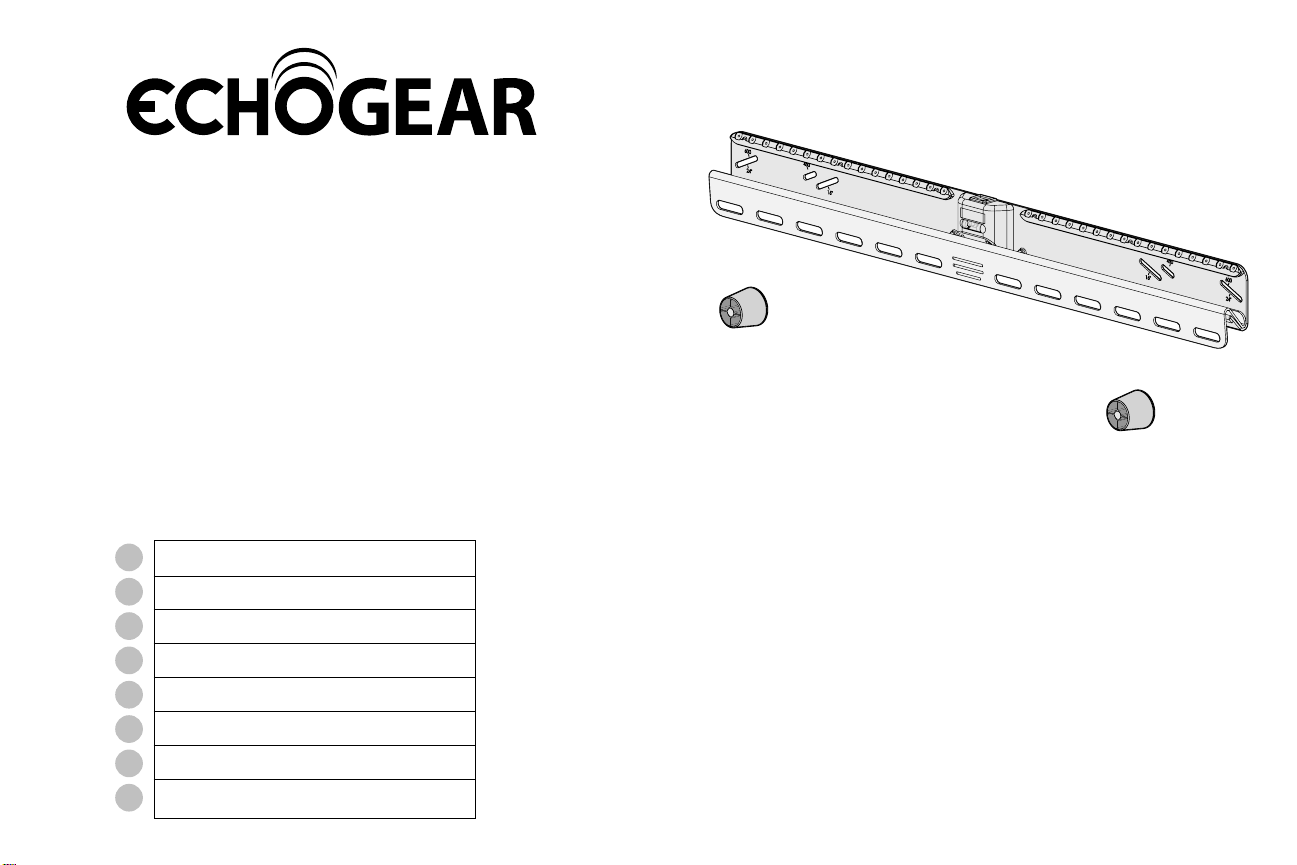
EGLD1
Drywall TV Mount
Instruction Manual
#YourGearUpgraded
Texto en español, página 24
Texte français page 27
Deutscher Text Seiten 30
Nederlandse tekst op pagina 33
Svensk text sida 36
日本語は39ページ
42
Русский текст: стр. 45
ES
FR
DE
NL
SV
JA
ZH
RU

2
IMPORTANT SAFETY INSTRUCTIONS. READ ENTIRE MANUAL PRIOR TO USE. SAVE These INSTRUCTIONS
Yea, the boring stuff ... but read it, so you don’t jack things up!
1
2
ACCEPTABLE
WALL TYPES
Wood studs
Drywall
Perfect! Perfect!*
Perfect!
TV (PLUS ACCESSORIES)
WEIGHT LIMIT
DO NOT EXCEED
Solid concrete or
concrete block UUHHH?!?
Unsure?
Contact The
Echogear Pros
(see back page)
for
Solid
concrete
or concrete
block
for
Wood
studs
for
Drywall
135 lbs.
(61.2 kg) 135 lbs.
(61.2 kg)
100 lbs.
(45.3 kg)
CAUTION:
DO NOT install into
plaster &lath walls
Metal Lath
Wood Lath
*Concrete kit is
NOT INCLUDED.
Call The Echogear
Pros for kit #CMK3.
Rough Plaster Surface
“You can think about it ...
but doooon’t do it.”
If your TV
weighs more,
this mount is
NOT compatible.
Visit echogear.
com to find
a compatible
mount.

3
Please read through these instructions completely to be sure you’re comfortable with this
easy install process. Also check your TV owner’s manual to see if there are any special
requirements for mounting your TV.
If you do not understand these instructions or have doubts about the safety of the
installation, assembly or use of this product, contact The Echogear Pros.
GRAB YOUR TOOLS
3
4
CAUTION: Avoid potential personal injuries and property damage!
This product is designed for use with wood studs, solid concrete and concrete block walls, and
drywall only.
The wall must be capable of supporting five times the weight of the TV and mount combined.
Do not use this product for any purpose not explicitly specified by manufacturer.
Manufacturer is not responsible for damage or injury caused by incorrect assembly or use.
MORE STUFF
TO READ
Drywall
Applications
NO DRILL
OPTION
Wood Stud
Applications
Concrete
Applications
1/8 in. (3.2 mm)
Wood
5/16 in. (8 mm)
Masonry
Phillips Screwdriver
Tape
Measure Stud Finder
Hammer
Hammer
Awl
Pencil
Drill Bit
Drill Bit
Electric
Drill
Electric
Drill
"Give it back
to Phil when
you finish"

4
M8 x 50mm
M8 x 25mm
M8 x 35mm
M8 x 16mm
M6 x 12mm M6 x 20mm M6 x 35mm
M4 x 12mm M4 x 35mm
What’s in the box ... What’s in the boooooxx
WARNING: DON'T FEED TO CHILDREN —This product contains small items that could be a choking
hazard if swallowed. Before starting assembly, verify all parts are included and undamaged. If any parts are
missing or damaged, do not return the damaged item to your dealer; contact The Echogear Pros.
Never use damaged parts!
NOTE: Not all hardware included will be used.
STUFF FOR STEP 1STUFF FOR STEP 1
TV Screws (qty. 2 each)
[Only one size fits your TV]
Washers
Spacers
[If necessary]
TV Bracket
qty.1
qty.2
qty.2
qty.2qty.4
M6
M6/M8
M8
01 02
03
04
M4
M4 qty.2

5
#10 x 2 ½in.
Fischer UX8 x 50R
14 ga. x 1 ¼in.
For CONCRETE installations ONLYFor DRYWALL installations ONLY
*WARNING:Thisproduct contains
a magnet. If an implanted medical device
such as a pacemaker or implantable
cardioverter defibrillator (ICD) is in
use, magnetic fields may aect the
operation of those devices, resulting in
serious injury or death. If you have an
implanted medical device, keep at least
13 cm (5 in.) between your device and
the magnet. Please consult with your
physician or medical professional prior
to using this product.
C1
Wall Plate
Concrete
Anchors
Nail
Washers
(Wood Screws)
Stando*
(Magnetic Leveling Feet)
Disc
(Adhesive backed)
(Wall Plate Screws)
FOR STEP 2B and STEP 2C ONLY
Wood
Screws
CAUTION: FOR STEP 2C ONLY:
Do not use in drywall or wood.
CAUTION: FOR STEP 2A ONLY:
Do not use in concrete or
plaster &lath.
NOTE: Anchors are NOT INCLUDED.
Contact The Echogear Pros to inquire about
anchor kit #CMK3.
STUFF FOR STEP 2STUFF FOR STEP 2 STUFF FOR STEP 3STUFF FOR STEP 3
Square
Driver Bit
TOY SURPRISETOY SURPRISE
Inside Every Box
FREE
qty. 1
05
qty. 1
11
qty. 2
06
#10
qty. 2
qty. 32
08
qty. 2
07
qty. 2
09
qty. 2
10
Built-in Level
Locking Mechanism
KEEP IN THE LOCKED POSITION
until instructed. UNLOCKED
LOCKED
6
1
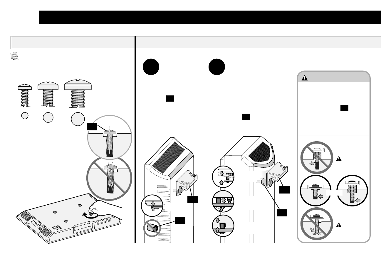
1.1 Select TV Screw Diameter 1.2 Determine TV Screw Length
NOTE: Only one screw size fits
your TV.
M6
M8
• Flat Back TV • Rounded Back TV
• Flat Back TV With
Extra Space Needed
[for cables or inset holes]
A
Too Short
Too Long
CAUTION:
Verify adequate thread
engagement with your screw/
washer/spacer combination
AND TV Bracket
04
.
-Too short will not hold the TV.
-Too long will damage the TV.
Correct
B
spacers
03 are
not necessary.
Rounded
Back
Flat Back
Cable
Interference
Inset
Holes
Use spacers
03 to create
extra space between the TV
and TV bracket.
04
04
Attach TV Bracket to Your TV
"Suggested uses for the
extra screws:
board game pieces,
industrial jewelry, sweet
corn holders, musical
instruments–like
maracas or 'monsoon'
sticks, stocking stuers,
currency (not most
countries) ..."
03
03
01
M4

7
Attach TV Bracket to Your TV
1.3 Attach the TV Bracket
04
• Flat Back TV
A
B• Rounded Back TV
• Extra Space Needed
Top of TV
02 01
0203 01
Spacer Options
8
2
IMPORTANT:
You must
determine your
wall construction
to correctly
secure the wall
plate to the wall.
Follow the
corresponding
step for your
installation
method.
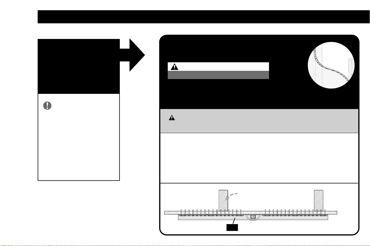
Attach Wall Plate to Wall
STEP 2A
on PAGE 10
DRYWALL
[TVs up to 100 lbs. (45.3 kg)]
CAUTION: Avoid potential personal
injuries and property damage!
DO NOT mount to patched areas/drywall seams /uneven walls
Drywall must be of sound construction with no water damage
If water damage ever occurs - remove the TV immediately
Your TV MUST be centered on the wall plate
Wood stud(s) are
okay to nail through
05
CAUTION:
DO NOT install into plaster &lath walls
9
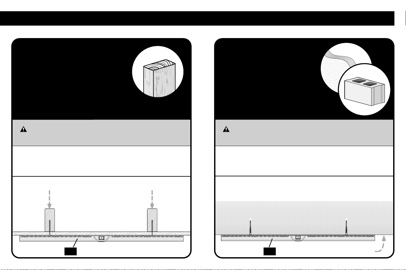
STEP 2B
on PAGE 12
WOOD STUD
[TVs up to 135 lbs.
(61.2 kg)]
Two stud centers must be located for
proper installation.
CAUTION: Avoid potential personal
injuries and property damage!
Attach Wall Plate to Wall
STEP 2C
on PAGE 14
SOLID CONCRETE
and
CONCRETE BLOCK
[TVs up to 135 lbs. (61.2 kg)]
CAUTION: Avoid potential personal
injuries and property damage!
The mount must be installed directly onto
the concrete surface (no surface covering).
05 05

10
2A
CAUTION: Avoid potential
personal injuries and property damage!
Drywall covering must be 3/8 in.
(9.5 mm) or greater
Drywall must be mounted on studs, no
more than 24 in. (609 mm) on center,
[minimum stud size: nominal 2 x 4 in. (51 x
102 mm) actual 1½x 3½in. (38 x 89 mm)]
Drywall must be sound with no water
damage. If water damage ever occurs
—remove the TV immediately
DO NOT mount to patched areas,
on drywall seams or uneven walls
Your TV MUST be installed centered
on the wall plate
CAUTION: Avoid potential personal injuries and property damage!
If ANY of the 32 nails
08 encounter excessive resistance (metal object) -
STOP and call The Echogear Pros.
DO NOT reuse nails
08 after removing. DO NOT use store-bought nails.
2A.1 Verify Your Wall 2A.2 Attach the Wall Plate
DRYWALL (only) INSTALLATION
[TVs up to 100 lbs. (45.3 kg)]
Min.
3/8 in. (9.5 mm)
1 2
05
05
05
OUTER HOLE OUTER HOLE
Position wall plate
05
on your wall, and secure a nail
08
in BOTH OUTER holes.
IMPORTANT: Wall plate
05
MUST be level when securing the second nail
08
.
DO NOT install into plaster &lath walls
08 08

11
DRYWALL (only) INSTALLATION
[TVs up to 100 lbs. (45.3 kg)]
IMPORTANT: Alternate installing the remaining thirty (30) nails
08 from side to side.
CAUTION: Avoid potential personal injuries and property damage! Thirty-two (32) nails
08 total,
must be used in wall plate
05 .
3
05
(qty. 30)
08
“naaailed it !”
“we can’t have
nice things!”
Go to STEP 3 on PAGE 16.
12
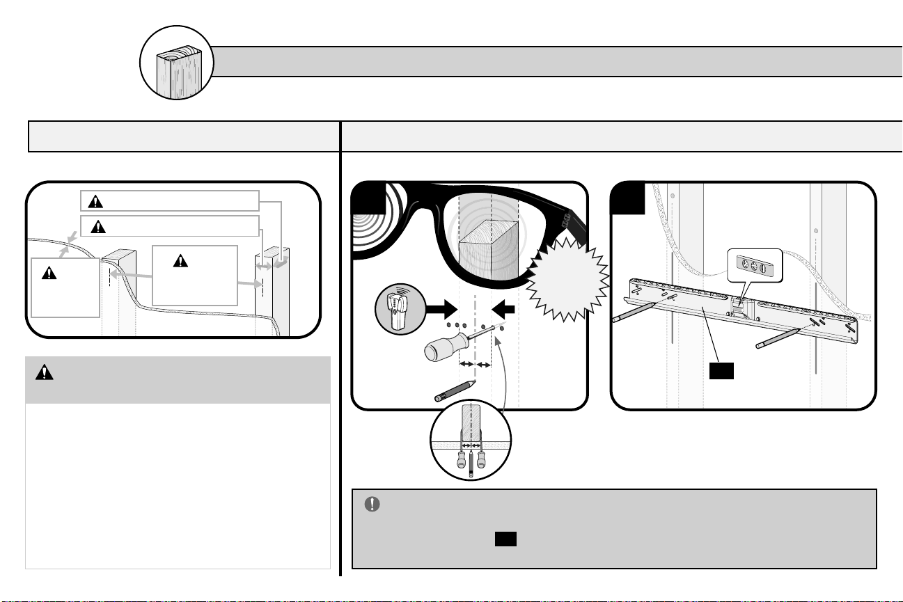
2B
CAUTION: Avoid potential personal
injuries and property damage!
Drywall covering the wall must not exceed
5/8 in. (16 mm)
Minimum wood stud size: nominal 2 x 4 in.
(51 x 102 mm) actual 1½x 3½in. (38 x 89 mm)
Minimum horizontal space between
fasteners: 16 in. (406 mm)
Stud centers must be verified – not all walls have
conventional 16 in. (406 mm) stud spacing
2B.1 Verify Your Wall
WOOD STUD INSTALLATION [TVs up to 135 lbs. (61.2 kg)]
1
Max.
5/8 in.
(16 mm)
Min.
16 in.
(406 mm)
Min. 1
½
in. (38 mm)
Min. 3
½
in. (89 mm)
2B.2 Attach the Wall Plate
2
05
IMPORTANT: If you DO NOT have two studs that are 16
inches (406 mm) to 24 inches (609 mm) apart –OR –you cannot
center wall plate
05 on your studs, follow STEP 2A on PAGE 10,
for drywall installation.
X-Ray
Specs
sold
separately
"favorite
pokey
device"
13
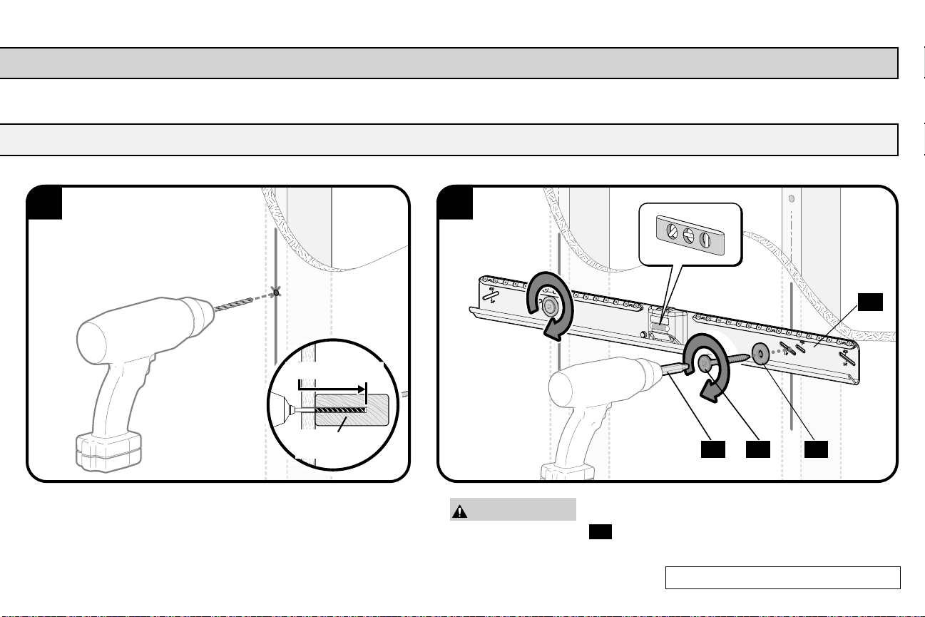
WOOD STUD INSTALLATION [TVs up to 135 lbs. (61.2 kg)]
3 4
CAUTION: Improper use could reduce the holding
power of screws
07 . DO NOT over-tighten the screws.
05
2½in. (63 mm)
1/8 in.
(3.2 mm) 11 07 06
Go to STEP 3 on PAGE 16.
2X
14
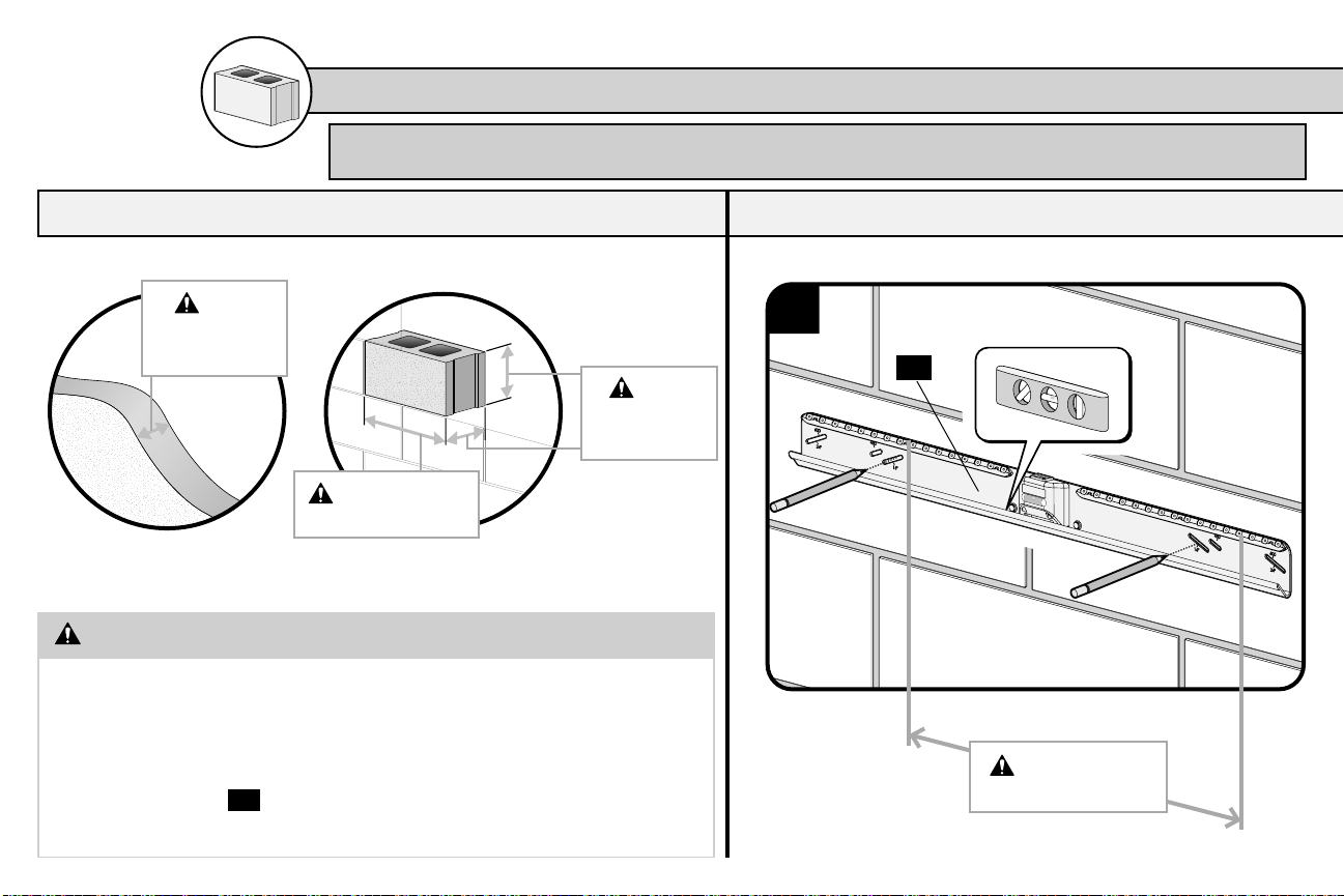
2C
2C.1 Verify Your Wall
SOLID CONCRETE /CONCRETE BLOCK INSTALLATION [TVs up to 135 lbs. (61.3 kg)]
CAUTION: Avoid potential personal injuries and property damage!
Minimum solid concrete thickness: 8 in. (203 mm)
Minimum concrete block size: 8 x 8 x 16 in. (203 x 203 x 406 mm)
Minimum horizontal space between fasteners: 16 in. (406 mm)
Mount wall plate
05
directly onto the concrete surface (no
wall covering)
2C.2 Attach the Wall Plate
05
1
Min. 16 in.
(406 mm)
Min.
8 in.
(203 mm)
Min. 16 in.
(406 mm)
Min.
8 in.
(203 mm)
Concrete Installation Kit is required [NOT INCLUDED].
Contact The Echogear Pros to inquire about kit #CMK3.
Solid Wall Block Wall

15
SOLID CONCRETE /CONCRETE BLOCK INSTALLATION [TVs up to 135 lbs. (61.3 kg)]
IMPORTANT: Never drill
into the mortar between blocks.
CAUTION: Improper use
could reduce the holding power
of screws
07 . DO NOT over-
tighten the screws.
002862.eps
5/16 in.
(8 mm)
2¾in. (70 mm)
2 3 4
C1 05
11 07 06
2X 2X
Flush

16
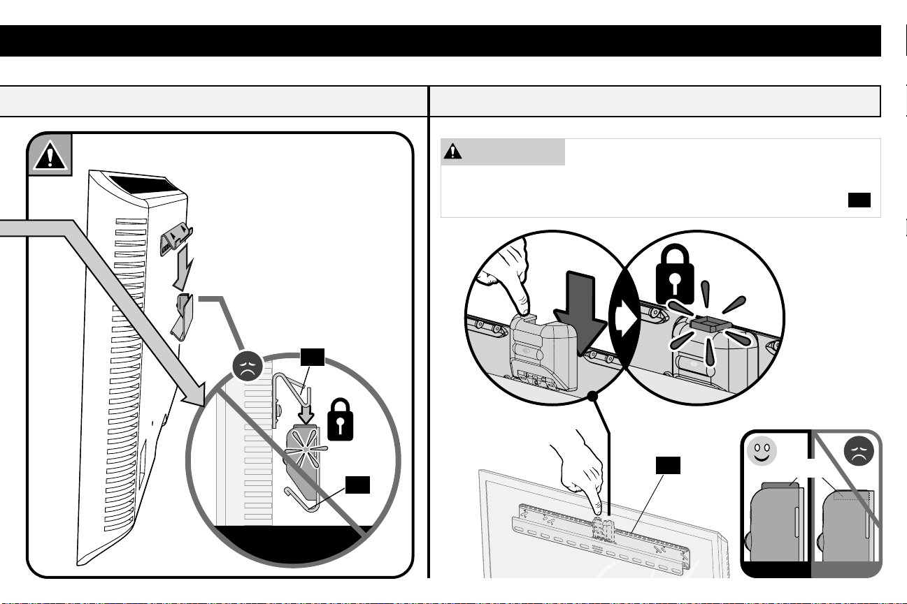
3
3.1 Unlock the Wall Plate 3.2 Hang Your TV
HEAVY! You may need assistance with this step.
Side View
05
0504
04
05
Let’s Hang
IMPORTANT: DO NOT lower TV straight down onto
wall plate
05 -- this will engage the lock. Safety latch must
be released for proper installation (See STEP 3.1).
"look with
your eyes"
17
Side View
04
05
Let’s Hang
3.3 Lock the Wall Plate
CAUTION: Avoid potential personal injury or
property damage! The locking mechanism must be
locked, so the TV is securely fastened to the wall plate
05
.
05
Side View Side View
Button
18
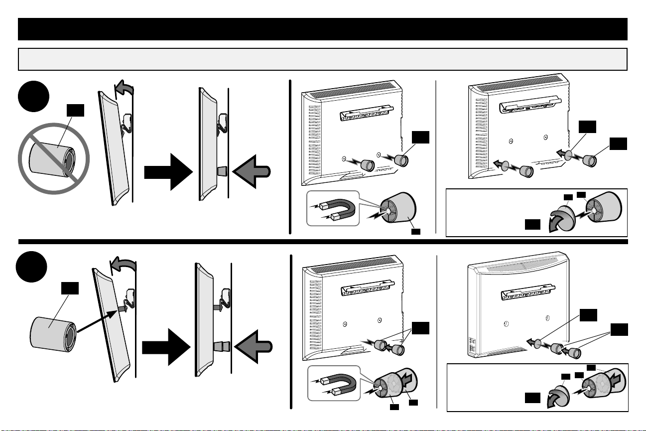
3.4 No Tilt Feature (OPTIONAL)
A
B
Let’s hang some more
03
03
For non-metal
back TVs, use
adhesive disc
10 .
For non-metal
back TVs, use
adhesive disc
10 .
09
09
09
09
10
10
09
10 09
10 09
09
09
09

19
Power it up
CAUTION: Avoid potential personal
injury or property damage!
DO NOT force open your TV when adding
cables. STOP lifting the bottom outward
when you feel resistance.

20
Adjustments
SIDE-TO-SIDE SHIFT
Slide the TV side to side to adjust positioning.
NOTE: Safety stops prevent over-shifting.
Make sure your TV is locked to wall plate
05
(STEP 3.3).
CAUTION: Avoid potential personal
injury or property damage!
FOR DRYWALL INSTALLATIONS:
DO NOT slide the TV side-to-side.
05
Table of contents
Other Echogear TV Mount manuals

Echogear
Echogear EGXLF1-KIT User manual

Echogear
Echogear EGLF3 User manual

Echogear
Echogear EGCM1 User manual

Echogear
Echogear EGLT3 User manual

Echogear
Echogear EGLF324 User manual

Echogear
Echogear EGLL2 User manual

Echogear
Echogear EGCM2 User manual

Echogear
Echogear EGMF1 User manual

Echogear
Echogear EGLT2 User manual

Echogear
Echogear EGAV-RTVSS1 User manual


