manuals.online logo
Brands
  1. Home
  2. •
  3. Brands
  4. •
  5. Mitsubishi Electric
  6. •
  7. Air Conditioner Accessories
  8. •
  9. Mitsubishi Electric PLP-6EAJ User manual

Mitsubishi Electric PLP-6EAJ User manual

Other manuals for PLP-6EAJ

1

This manual suits for next models

1

Other Mitsubishi Electric Air Conditioner Accessories manuals

Mitsubishi Electric PAC-SNH21HS-E User manual

Mitsubishi Electric

Mitsubishi Electric PAC-SNH21HS-E User manual

Mitsubishi Electric EHGT17D-YM9ED User manual

Mitsubishi Electric

Mitsubishi Electric EHGT17D-YM9ED User manual

Mitsubishi Electric PAC-RB01BC User manual

Mitsubishi Electric

Mitsubishi Electric PAC-RB01BC User manual

Mitsubishi Electric RG79F146H03 User manual

Mitsubishi Electric

Mitsubishi Electric RG79F146H03 User manual

Mitsubishi Electric PAC-SG85DR-E User manual

Mitsubishi Electric

Mitsubishi Electric PAC-SG85DR-E User manual

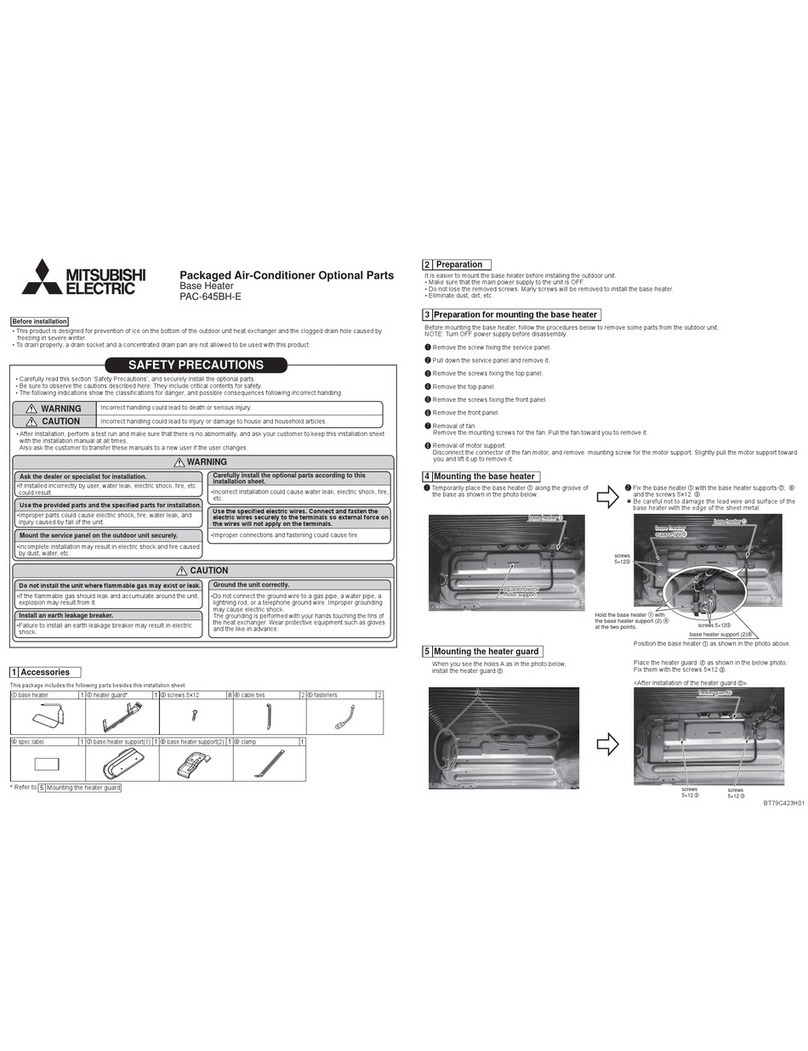
Mitsubishi Electric PAC-645BH-E User manual

Mitsubishi Electric

Mitsubishi Electric PAC-645BH-E User manual

Mitsubishi Electric PAC-SG95LE-E User manual

Mitsubishi Electric

Mitsubishi Electric PAC-SG95LE-E User manual

Mitsubishi Electric RCN-K-E User manual

Mitsubishi Electric

Mitsubishi Electric RCN-K-E User manual

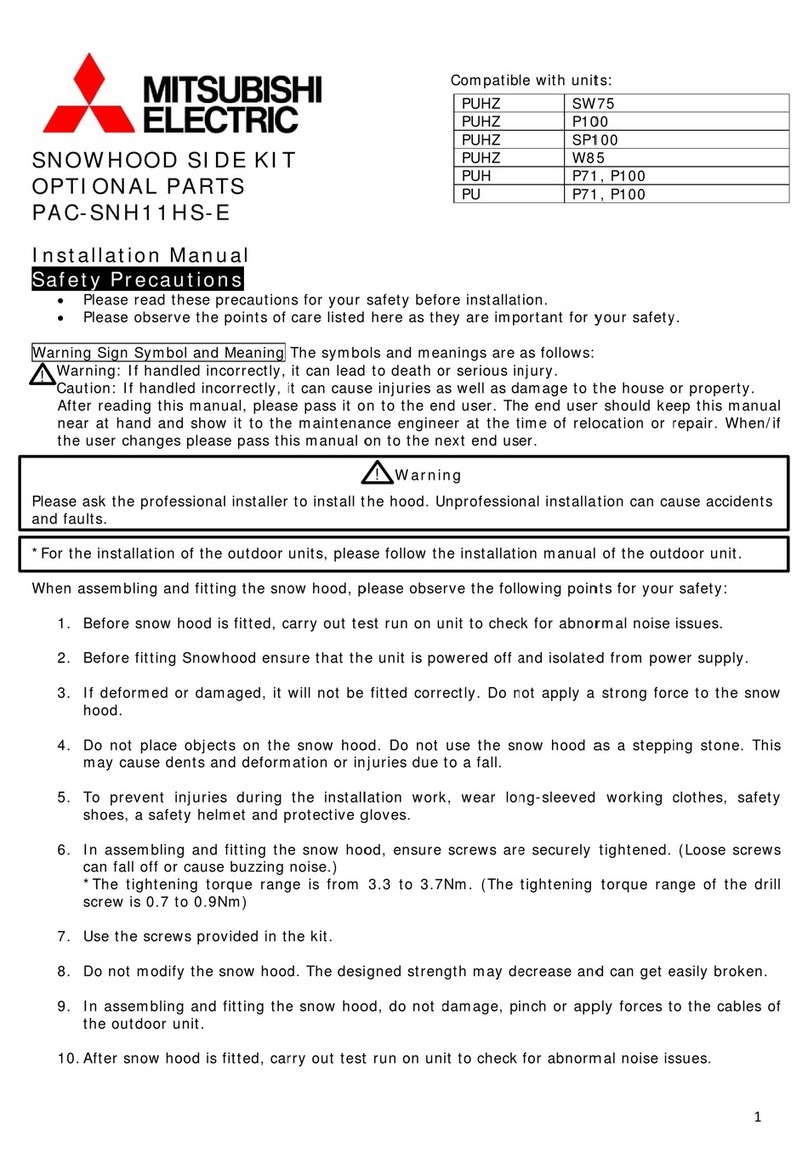
Mitsubishi Electric PAC-SNH11HS-E User manual

Mitsubishi Electric

Mitsubishi Electric PAC-SNH11HS-E User manual

Mitsubishi Electric FR-A800 User manual

Mitsubishi Electric

Mitsubishi Electric FR-A800 User manual

Mitsubishi Electric AE-200A-50A User manual

Mitsubishi Electric

Mitsubishi Electric AE-200A-50A User manual

Mitsubishi Electric MSZ-RW25VG User manual

Mitsubishi Electric

Mitsubishi Electric MSZ-RW25VG User manual

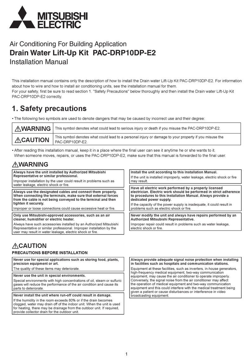
Mitsubishi Electric PAC-DRP10DP-E2 User manual

Mitsubishi Electric

Mitsubishi Electric PAC-DRP10DP-E2 User manual

Mitsubishi Electric PFR-12-18 Instruction sheet

Mitsubishi Electric

Mitsubishi Electric PFR-12-18 Instruction sheet

Mitsubishi Electric PAC-645BH-E User manual

Mitsubishi Electric

Mitsubishi Electric PAC-645BH-E User manual

Mitsubishi Electric PAC-SNH21HB-E User manual

Mitsubishi Electric

Mitsubishi Electric PAC-SNH21HB-E User manual

Mitsubishi Electric PAC-SNH11HB-E User manual

Mitsubishi Electric

Mitsubishi Electric PAC-SNH11HB-E User manual

Mitsubishi Electric CMY-Q100CBK User manual

Mitsubishi Electric

Mitsubishi Electric CMY-Q100CBK User manual

Mitsubishi Electric PRE-12 Instruction sheet

Mitsubishi Electric

Mitsubishi Electric PRE-12 Instruction sheet

Mitsubishi Electric PAC-SK38HR-R User manual

Mitsubishi Electric

Mitsubishi Electric PAC-SK38HR-R User manual

Mitsubishi Electric PAC-TZ02-E User manual

Mitsubishi Electric

Mitsubishi Electric PAC-TZ02-E User manual

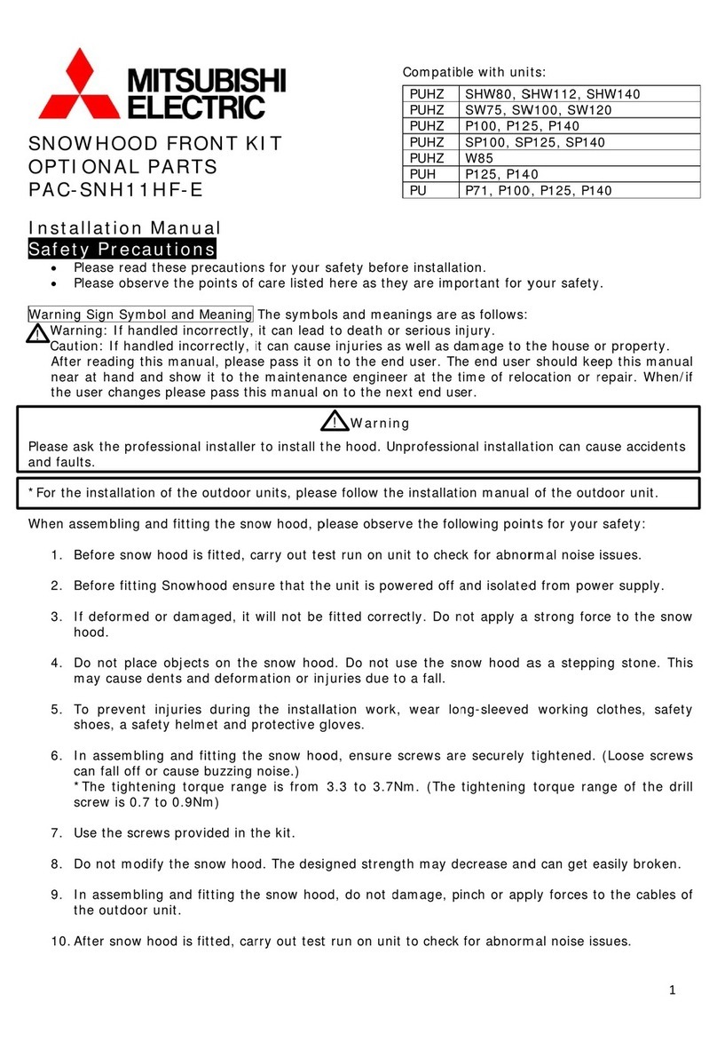
Mitsubishi Electric PAC-SNH11HF-E User manual

Mitsubishi Electric

Mitsubishi Electric PAC-SNH11HF-E User manual

Mitsubishi Electric SPTB1 User manual

Mitsubishi Electric

Mitsubishi Electric SPTB1 User manual

Popular Air Conditioner Accessories manuals by other brands

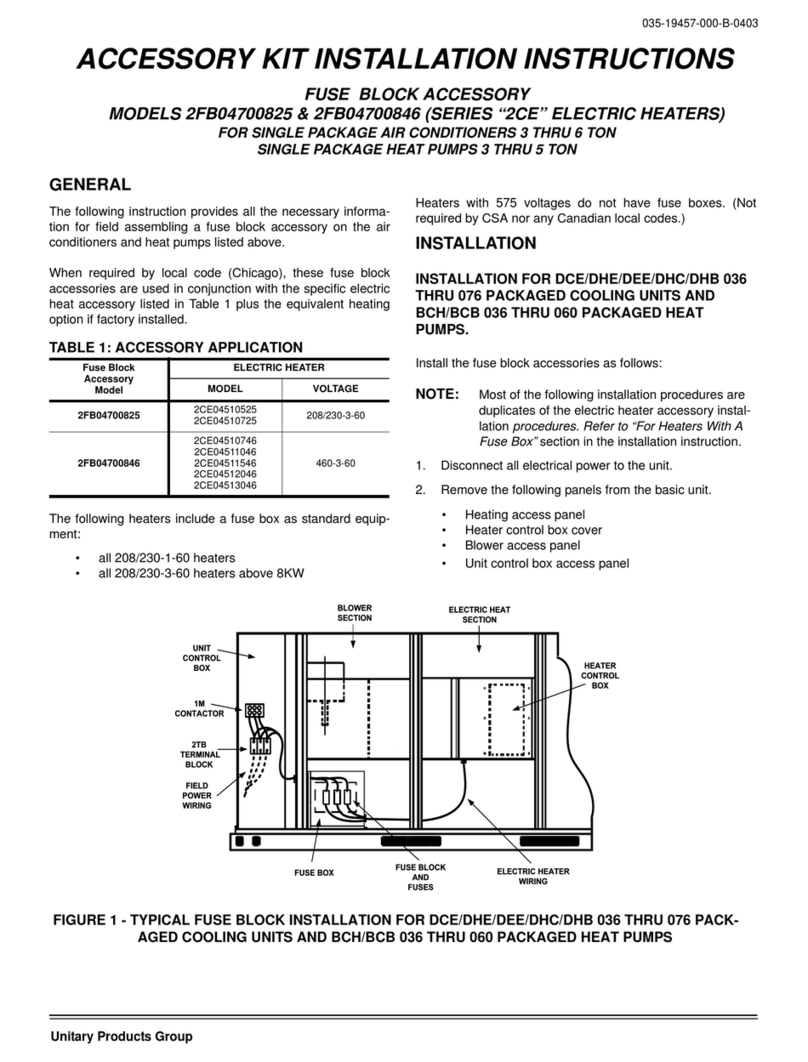
Unitary products group 2CE Series installation instructions

Unitary products group

Unitary products group 2CE Series installation instructions

Qlima EU-ODZ104 user manual

Qlima

Qlima EU-ODZ104 user manual

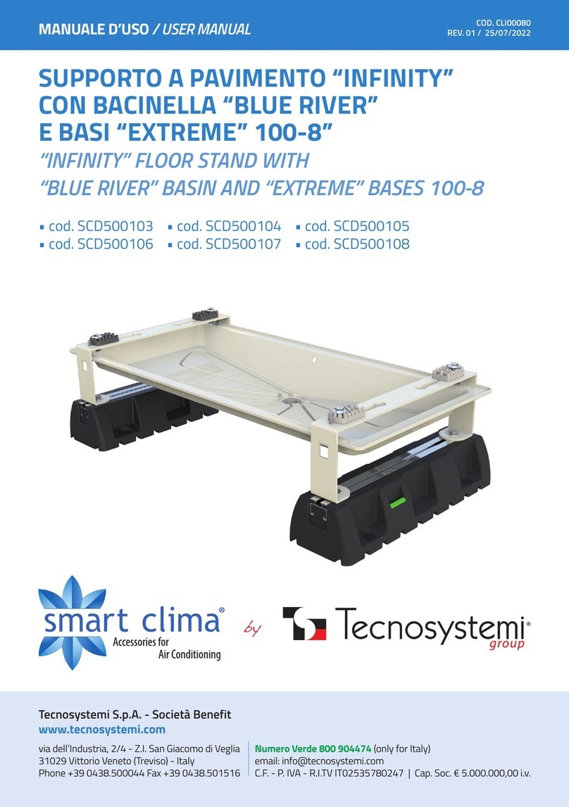
Tecnosystemi smart clima SCD500163 user manual

Tecnosystemi

Tecnosystemi smart clima SCD500163 user manual

Waeco AirCon Service Center ASC 5300 G operating manual

Waeco

Waeco AirCon Service Center ASC 5300 G operating manual

American Standard BAYSQRD001AA Installer's guide

American Standard

American Standard BAYSQRD001AA Installer's guide

Bimar AP11 Instruction booklet

Bimar

Bimar AP11 Instruction booklet

Mitsubishi PAC-SJ41TM-E installation manual

Mitsubishi

Mitsubishi PAC-SJ41TM-E installation manual

Tecnosystemi Smart Clima SCD500084 user manual

Tecnosystemi

Tecnosystemi Smart Clima SCD500084 user manual

Samsung MIM-H04U User & installation manual

Samsung

Samsung MIM-H04U User & installation manual

Waeco AirConServiceCenter ASC 3500 G LE operating manual

Waeco

Waeco AirConServiceCenter ASC 3500 G LE operating manual

Fujitsu UTZ-KXGC installation manual

Fujitsu

Fujitsu UTZ-KXGC installation manual

Hitachi E-52XN installation manual

Hitachi

Hitachi E-52XN installation manual

ActronAir LR7-1W Operation manual

ActronAir

ActronAir LR7-1W Operation manual

EMI 550000565 installation instructions

EMI

EMI 550000565 installation instructions

Tecnosystemi ARIA 2 ELEGANCE CR user manual

Tecnosystemi

Tecnosystemi ARIA 2 ELEGANCE CR user manual

GE RAB71B Standard installation instructions

GE

GE RAB71B Standard installation instructions

RRS Jade XRD-01RDHAM3 Series Installation instruction

RRS

RRS Jade XRD-01RDHAM3 Series Installation instruction

Galletti estro UTN PWN quick start guide

Galletti

Galletti estro UTN PWN quick start guide

manuals.online logo
manuals.online logoBrands
  • About & Mission
  • Contact us
  • Privacy Policy
  • Terms and Conditions

Copyright 2025 Manuals.Online. All Rights Reserved.

BH79A277H01
•
MITSUBISHI
....
ELECTRIC
MITSUBISHI ELECTRIC Package Air-Conditioner Grille {Optional Part)
Automatic Filter Elevation Panel Installation Manual (PLP-6EAJ I
PLP-6EAJE (with "i-see Sensor"))
•11,4;,,~)k4!i!iit·
1
it'I
•
Before
installation,
make
sure
to
read
all
the
"Safety
precautions
that
must
be
followed"
and
perform
it
accurately.
•
The
precautions
herein
provide
very
important
points
regarding
safety
.
Make
sure
you
follow
them
.
•
Symbols
used
in
this
manual
are
categorized
as
follows
according
to
the
degree
of
risk
when
used
improperly:
~
Warning
Describes
warnings
that
must
be
observed
to
prevent
serious
consequences,
such
as
serious
injury
or
death
of
the
user.
Lt,Caution
Describes
precautions
that
must
be
observed
to
prevent
damage
to
the
unit.
•
After
installation,
describe
the
user
"Safety
Precautions
",
how
to
use,
and
how
to
care
for
and
clean
the
unit
following
the
operation
manual
,
and
test
run
the
unit
to
check
whether
there
are
any
problems.
In
addition,
direct
the
user
to
keep
this
installation
manual
together
with
the
operation
manual,
and,
should
the
users
change,
to
give
the
manuals
to
the
new
user.
~Warning
Wiring
must
be
done properly using specific cables and fixed
so
Do not mixsubstances otherthan the designated refrigerant
in
that external pressurefrom the cable will not transmitto
the
the refrigerant cycle when installing and/or moving the unit.
terminal area. Neversplice the cables
for
wiring. •
If
air
or
other substances
mix
in, abnormal high-pressure will occur
in
•
If
the connection and/orfixation are notdone properly,
or
if
the cables the refrigerant cycle, which may cause explosion.
are spliced, heat
or
fire may result.
The
unit
must not
be
moved
or
reinstalled by the user.
Never makealterations
to
the
unit.
•
If
the unit
is
installed improperly, water leakage, electric shock
or
fire
• Consult with a dealer
for
repairs.
If
alterations
are
doneon the unit
or
may result.
Ask
the
dealer
or
an authorized company to do so.
the unit
is
repaired improperly, waterleakage, electric shock
or
fire
Use genuine Mitsubishi parts such as humidifierand high
may result. performancefilters (sold separately).
Ask
the dealer or an authorized technician to install the unit. •
Ask
an authorized company
to
install.
If
the unit is installed by the
user improperly, waterleakage, electric shock
or
fire may result.
•
If
the unitis installed improperly by the user, water leakage, electric
shock
or
fire
may
result. Terminal board cover (panel)
of
the indoor/outdoorunitmustbe
Installation must be properly donefollowing this installation manual. inSialled properly.
•
If
the unitis installed improperly, water leakage, electric shock
or
fire • Ifthe terminal board cover (panel)
is
installed improperly, fire
or
It electric shock may result due to dust
or
water.
;:=
m=a=y=r=e=s=u=·
=========================================:
;:
================================================
='.
Installation
must
be done in proper order in case
of
strongwind Make sure the refrigerant has not leaked after installation.
such as storms and earthquakes. •
In
case the refrigerant leaks into the room and comes in contactwith
•
If
the unit is installed improperly, there
is
a riskthat a fall may result. a fan heater, heater,
or
stove burner, noxious fumes maybe produced.
The unitmust be securely installed on a surface that
is
able
to
support
the
weight ofthe unit.
•
If
the surface does nothave sufficientstrength, accidents may result
dueto falling
of
the unit.
If
the unit
Is
to
be Installed In a small room, takemeasures to
prevent exceeding the concentration limit
of
refrigerant in the
case
of
refrigerant leakage.
•
Ask
a dealeraboutmeasures
to
prevent the exceeding the
concentration limit.
If
there is anychance
of
refrigerant leakage and
its concentration exceedsthe limit,
it
may result in lack
of
oxygen.
Before installation(Environment)
Electrical work must
be
done by an authorized engineerfollowing
"Technical standards for electrical equipment", "Extension Code"
and this installation manual and using dedicated communication
circuit and rated powervoltage/circuit breakers.
• Ifthe electrical circuit does not have sufficient capacity
or
if
the unit is
installed improperly, electricshock
or
fire may result.
Turn
off
the main power before
the
installation work.
• Otherwise, injury
or
electricshock may result.
Ventilate the room
if
refrigerant leaks outduring installation.
• When refrigerant comes in contact with fire, noxious fumes may be
produced.
J
~Caution
Do not usethe unit in unusual environment. The unitmust not
be
used
for
special purposes such as
•
If
used in
an
environmentwith a large amount
of
volatile oil
(including mechanical oil), steam,
or
sulfidizing
gas
or
where it is high
in salt content such as a seashorewhere
the
outdoor unit may
become blocked bysnow, performance
may
dropsignificantly
or
parts
may become damaged.
the
storage
of
precision apparatuses, food, animals and plants,
and
art
objects.
•
It
may cause deterioration in quality
of
the objects.
Do not Install the
unit
above objects that should not getwet.
Do not Install
the
unit
In
an area where flammable
gas
may be
generated, flow in, be retained or leaked.
• In case gas leaks around the unit, fire or explosion may result.
•
In
case humidityexceeds 80%
or
the drain outlet is blocked, dew
may
fall from the indoor unit. When the heating function is on, waterleaks
from the outdoor unit; intensive drain work
may
be done to the
outdoorunit as needed.
If
the unit
Is
Installed
In
a hospital or telecommunlcatlons office, preparation
for
noise
must
be adequately completed.
• The effect
of
inverterequipment, private power generators, high-frequency medical devices and radio communication devices may result in
malfunctions and/ordamage
of
the air-conditioner. Air-conditioners may affectmedical devices
or
telecommunications devicesto interfere with
medical treatment
or
cause adverse effects such as disturbance
of
broadcasting and/or noise bursts.
1.
IIncluded partsI(This manual and following parts are included.)
Standard grille
Part
Number/ 0 Grille
Name
Quantity
Shapes/
Sizes
Grille with i-see Sensor
@ Installation gauge @Tag Wireless remote
© controller forAutomatic @ Battery
FilterElevation Panel
0
Lithium battery
CR2025
3V
Remote
@controller
holder ©
screw
2
@
Screw
®i-see Sensorcorner panel Note: Neverforce pressure on thevane,
it
may result in damage.
Parts
G)
to
(J)
above and
...!J
4><16
L!J
jf"
0 :i
·~
,.
-~"fl
Neverforce pressureon the lens
of
!@
I-see Sensor cornerpanel,
it
may result in damage.
' Ceiling surface
Main unit
,,
2,
IPreparation before installing the grille I
I
Confirming
the
location
of
the
main
unit
I
•Check
whetherthe opening holes
of
the ceiling are within
the
following range:
860
><
860
to 910
><910
Measurement
@Installation gauge
of
opening holes
(Insert into the main unit)
of
the ceiling
•Using
included installation gauge@, locatethe ceiling surface and the main unit.
If location
of
the ceiling s
urf
a
ce
and the main unit does not match, wind leakage,
dewfail
or
damage
of
the vane
may
result. Note:
The
ga
mustbe in the ran e
of
17 to
22
.
Ifit exceeds
or
fails below
the
range,
•Turn
off
the main power(short circuit breaker).
~
Turn
off
the
main
ower.
~
Warning
•If
the main poweris notturned
off
,
injury
or
electric shockmay result.
[Remarks]
The
grille
must
not
be
painted
by
the
user.
•Itmay result extreme malfunction
or
the damage
of
parts.
Ask
the
dealer
or
an authorized technician
to
aint.
I
Installing
the
wired
remote
controller
I
•The
intake grille elevation function can be controlled with the wired remote controller. There are 2 methods
for controlling
the
intake grille elevation function: Use the elevation function
for
all
the
main units which are
controlled by the remote controller
at
once, and use the elevation function for each main unit individually.
(Please refer to
the
oper
ation manual
for
the operation method.)
Install
the
remote controller
in
a place where you can observe all the indoor units managed with it.
Otherwise,
the
lowering grille may hit people
or
objects and cause damage
to
them.
I
Installing
the
remote
controller
holder
(For Automatic Filter Elevation Pane
l)
I
•The
remote controller holder
is
included. Use the holderto prevent losing
the
wireless remote controller.
•In
stall
the
wir
eless remote controllerfor Automatic FilterElevation Panel
in
the following locations.
• Locations that
ar
e notexposed to dire
ct
sunlight • Locations
in
which
it
is
ea
sy tooperate the
• Locations that are not ne
ar
sources
of
heat remote controller and see its display
• Locations
th
at are not exposed to
co
ld
air
(hotair) • Locations thatare
out
of
the reach
of
children
being blown from
the
indoorunit • Locations that are
not
exposed to oilysmoke, and so on
•To
install
the
wireless r
em
o
te
controller for Automatic Filter Elevation Panel, secure the remote controller holder
to a wail using the included screws, a
nd
then
fit
the wireless remote controller
for
Automatic Filler Elevation
Panel into the holder.
I
Removing
the
intake
grille!
•Remove
the tape that secures the intake grilleand remove the intake grille from t
he
grille.
Not
e: You will find the limit switch for storing and
det
ecting intake grille shown
in
the
right figure.
Make sure you do not damage the limitswitch when operating.
I
Removing
the
corner
panel
I
~
lScrew
-r
~~
lo
se-
up
• Loose the 4 screws on the corner,
I..':&>!
slide the corner panel in the
dir
ection
LI
~c
rew
of
the
arrow
(1)
in
the
figure and
A:f
¥ ~
remove the corner panel. Cornerpanel
@Wireless remote
controller for Automatic
Filter Elevation Panel
!ID
Remote controller holder
--
----
-
---------
~
---------
~
3,
ISelection
of
airoutlets I
•You can sele
ct
11
differe
nt
patterns
of
air
outlet directions on this grille.
•Sel
ect
a pa
tt
ern
of
air outlet directions.
More than two directions must be selected.
Notes 1. When
ch
anging the number
of
directions, you need an air
outlet shutter plate, which is optional part. An air outlet shutter
plate will be
att
ached to the indoor unit; configurati
on
must be
done before attaching the grille on
the
main unit.
2. Do notselect 2 directions in a hotand humid environment.
(Dew
formation
or
dew drop may r
es
ult.)
4 dir
ec
tions 3
dir
ections 2 directions
§ ( 1 pattern ) ( 4 patterns ) ( 6 patterns )
'fl
Initial setting Block 1
of
the
air
outlets on Block 2 of the air outlets on
~
the main unitwith shutter the ma
in
unitwith s
hutt
er
'5
❖
·-o
'¢.oo.
~
V
c>~~
~
0
"'
i
CL
Before installation(Relocation)
~Caution
Do
not neglect damaged platforms.
•
If
leftdamaged, the unitmayfail and result in injury.
Transport
of
the product must be done carefully.
•
In
principle, products over 20
kg
must be carried
by
two
or
more
people. Make sure you move the product holding onlythe designated
handle but nota PP band and such. Use protectors to prevent injury;
do not touch the fins
or
the
edge
of
part
with your bare hands.
Appropriately dispose
of
packages.
• Packaging may contain metal objects such as "nails" and wood chips.
So injury may result ifdisposal is neglected.
Make sure that
the
joints are locked securely and they
do
not
come
off
from all
of
4 holes.
• Otherwise,
the
intake grille may drop
off
and cause an injury
or
a
failure.
Before electrical work
Do notwash the air-conditioner.
• Doing
so
maycause electric shock. J
Drain piping must be done properly according tothe installation
manual
to
drain
water
and
must
be
heat Insulated to prevent bedewlng.
•
If
piping is notproperlyinstalled, waterleakage mayresult, which will
make the ceilings, floors
or
otherhousehold Items wet.
Make sure heat insulation
for
refrigerant piping
is
properly
installed to prevent bedewing.
•
If
heat insulation is not done properly, bedewing
of
the surfaces such
as piping mayresult, which will make the ceilings, floors,
or
other
valuable items wet.
• Insulation forthe
joint
part must be done afteran
air
tightness test.
Make sure
to
hang the safety strap
of
the intake grille while
temporarily installing the grille.
• Otherwise, the intake grille may drop
off
and cause an injury
or
a failure.
~Caution
Makesure to install a short circuit breakerto the power. Unit must be grounded.
•
If
a
short
circuit breakeris not installed, electric shock mayresult.
Use properelectrical cables to meet the standard for current
capacity.
• Do notconnectthe ground wires with ground wires for gas pipes,
waterpipes, conductor rods,
or
telephones.
If
the unit is notproperly
grounded, electric shock may result.
•
If
improperelectrical cables are used, shortcircuit, heat,
or
fire may
result. Use fuses with appropriate capacity such as short circuit breaker,
hand switch (switch +type B fuse), and circuit breakers forwiring
devices.
Electrical wiring must be done without tension.
•
If
there istension
on
the cables, wire disconnection, electric shock,
or
fire may resuIt.
•
If
fuses, wires, and copper wires with larger capacities are used,
damage
or
fire may result.
Start
the
electrical work after turning
off
the main power.
• Otherwise, electric shock, damage,
or
failure may result.
Before test runs
~Caution
Do not operate the unitwithout the grille
or
guard. Do nottouch refrigerant piping when operating with bare hands.
•
If
you touch rotating, hot
or
high-voltage parts
of
the equipment,
injury may result from being snagged or burnt,
or
from electric shock. • Refrigerant piping when operating becomes cold and hot, depending
on the condition
of
the flowing refrigerant.
If
touched with bare
ha
nds,
frostbite
or
burns may result.
Do
notoperatethe unitwith wet hands. Do notturn
the
unit
off
soon after operation stops.
• Electricshock may result.
Turn It on more than 12 hours before operation.
• Make sure you wait
for
more than 5 minutes.
If
it is turned
off
too
soon, water leakage
or
damage may result.
Do notoperate the unit without
air
filters.
•
If
operation starts as soon as the unit
is
turned on, damage may
result. Do not turn it
off
during the season. • Dirt mayget clogged inside and may result in damage.
3,ISelection
of
airoutlets I(continued from the previous page)
•Change
the settings depending on the number
of
air
outlets and the ceiling heightwhere the main unitis installed.
If
not changed, failure may result
or
users mayfeel discomfort.
Note: Do not
set
up for lowceilings
in
a hotand humid environment. (Dew drop may result.)
I
When
used
in
combination
with
PLA-EA
I
Configuration will be done on the remote controller. Refer
to
the section "Function Se
tt
ing" in the installation manual
of
the
remote controller
or
the section "Function Setting on the Remote Controller" in the installation manual
of
the main unit.
I
When
used
in
combination
with
PLFY-EM
I
Set up the switches on controller board
of
the main unit as shown in the following table.
<Ceiling
height
and
number
of
air
outlets>
Main unitType 20
to80
Type
Low ceiling Standard High ceiling Low ceiling 100to 125Type
Standard High ceiling
sw21-1
l
sw21-2
sw21-1lsw21-2
sw21-1
l
sw21-2
sw21-1
lsw21-2
sw21-1
I
sw21-2
sw21-1
lsw21-2
OFF I ON OFF I
OFF
ON I OFF OFF I ON
OFF
I OFF ON I OFF
4 directions SW21-3 OFF 2.5m 2.7m 3.5m 2.7m 3.2m 4.5m
SW21-4 ON
3 directions SW21-3 OFF 2.7m 3.0m 3.5m 3.0m 3.6m 4.5m
SW21•4 OFF
2 directions SW21-3 ON 3.0m 3.3m 3.5m 3.3m 4.0m 4.5m
SW21-4 OFF
Note: Swit
ch
setting is necessary exceptfor the column highlighted in gray. (Column highlighted in
gr
ay is the initial setting).
4.1
Installing grilleI <Hook is in the raised position>
1)
Preparations
Make
sur
e
to
flip 2 hookson the grille up.
2)
Temporary
installation
of
grille
Join t
he
corner
of
drain pipe on the main unitwith
the cornerwith hole on the grille and putthem
togethertemporarily
by
hanging the hook
of
the
grille
to
the claw
of
the main unit.
•Make
sure the lead wires
of
the grille do not
get
caught between the main unit and the grille.
•Never
force pressure on
the
grillewhile the
tempora
ry
installation. It may result in accident
and damage.
3)
Fixing
the
grille
•By
tightening the pre-installed screws,
fix
the grille onto the main unit.
Note: Make sure there is
no
gap between
the
main unitand the grille
or
between the grille and the ceiling surface.
r !~~
~·
'"
C
·1·
c::::
rf
\
eI
Ing su ace Grille
•If
there is a gap between the grille and
the ceiling: With the grille a
tt
ached, slightly
adjust the installation height
of
the main unit
and clear the ga
p.
[Remarks] When tightening the screw, make sure that
the tightening torque is 2.8N• m
to
3.6N · m.
Neveruse an impact screw driver.
• It may result in parts damage.
Lead wires of
the grille
4)
Wiring
conn
e
ctions
r
..l!L
~
+-
--1
--ir-
CNV connector
I
Wiring
connections
for
van
e
motor
I
1.
Loose the 2 screws fixing the electrical box cover on the main unit, and slide the coverto open.
2. Make sure to connect a connec
tor
forvane motor(white, 20 poles) to
CNV
connector(white)
on the controller board
of
the main unit.
3. Lead wires thatlead
off
the
grille must be held togetherwithoutslackusing a clamp into the
electrical box. /'ii
Note: Lead wires
of
thegrille must be held together using a clamp on the main unit
so
Electri
ca
l box ·,
that
th
ey do notcont
ac
t the strings of elevation machine motor box.
!Wiring
connections
for
elevation
machine
I
4. Ro
ule
the lead wires (blue, 4 poles)
of
the elevation m
ac
hine of the grille from the side of the
electrical box on the main unit.
5. Make sure to connect them
to
CN4G (blue) on the controller bo
ar
d
of
the main unit.
6. Earth wires
of
the grille must be fixed with the included
sc
rews in the el
ec
trical box
of
the main unit.
Indoor
unit
must
be grounded.
~Caution
• Do notconn
ec
t
th
e ground wires with ground wires for gas pipes,
water pip
es
, conduct
or
rods, or telephon
es
.
If
the indoor unit is
no
t
prope
rl
y grounded, electric shock may result.
Ground wire
fixing position
7. Lead wires for elevation machine
of
the grille mustbe fixed with the cable band without sla
ck
inside the electrical box.
on the
co
ntroller
board
Cl
amp
Continued to the next page
5,
IInstalling corner panels I
IInstalling
of
corner panels I
Slide the corner panelsto each cornertowards the arrow and
fix
with
the
provided screws.
Signal receiver
for the remote
controller
(default position)
Intake grille
Installation location
for
the i-
see
Sensor
corner panel
(default position)
~~-
Drain pipe
....__
Refrigerant pipe
~
l~rew
··
c,~,paoell [
~~"PS
f~
.
~
crew
•For
the cornerpanels with safety strap, make sure to hang the strap
on
the
hook
of
the grille securely.
Note:
If
the
safety
strap
is
not
hanged
properly,
there
is
a
risk
the
corner
panel
may
fall.
IInstalling signal receiver corner panel (default position) I
1. Route the lead wires (white, 9 poles)
for
signal receiver cornerpanel
from the side
of
the electrical box
on
the
main unit. Claw
of
bellmouth
2. Make sure to connect
to
CN90 (white)
on
the controller board
of
the main unit.
3. Make sure that lead wires
of
signal receivercornerpanel is passed through the
claw
of
bellmouth.
Theremaining lead wires must be held togetherwithout slack using the clamp
into the electrical box;
so
that they
do
notcontact the strings
of
elevation
machine motorbox.
4. The electrical box
cover
of
the main unitis closed again with 2 screws.
5. Install thesignal receiver corner panel with to the grille and
fix
with
the screws.
Notes:
1.
Makesure the strings
of
the elevation machine motorare not
caught in
the
cover
of
electrical box
of
the main unit.
If
they
get
caught, they may becut off.
2. The signal receiver cornerpanel cannot be installed
on
the drain
pipe side
for
the main unit.
If
installed forcibly,
ii
may
result
in
the failure.
Screw
Elevation
machine
motor box
Cable band
CN90
on
controller
board
Electrical box
String
IInstalling i-see Sensorcorner panel (default position) I
Pass the lead wires
of
i-seeSensor cornerpanel through the square hole
of
the grille.
Lead wires
of
i-see
Sensorcorner panel
Square hole
of
the -
==::::::::r
it
grille
Q
3. Lead wires for the i-see Sensorcornerpanel must be held togetherinto the electrical box
without slack using
the
clamp.
4. To reinstall the cover
of
electrical box, reverse the procedure
1.
5. Install the i-see Sensorcorner panel to the grille and fix with the screws@.
Note:
The
i-see Sensorcornerpanel cannot be
in
stalled on t
he
drain pipe side for the main unit.
If
installed forcibly,
it
may result in the failure
of
i-see Sensorcorner panel.
s.IInstalling corner panels lccontinued from the previous page)
IRemoving the signal receiver corner panel I
• Remove the signal receivercomer panel according to
the
following importantpoints.
CN4Zand CN5Y
on
the
controller
board
Lead wires
of
i-see Sensor
corner panel
Clamp
Screw@
~
i-s
ee Sensor
cornerpanel@
1. Because the lead wires (white, 9 poles) forthe signal receiver comer panel are fixed to the back
of
the grille using a clamp,
the lead wires must
be
removed from the clamp.
2. Loosen the screw
in
the comeron thefront
of
the grille and remove the signal receivercomer panel.
Note:
If
the i-seeSensorinstall position is changed from
de
fault position, change the function
settings by referring to main unit installation manual.
Signal receiver corner panel
defaultposition
Signal receiver lead wires (white)
<Back
of
the grille>
6.
ISetting up the lowering distance
of
intake grilleI
•You
can
set
up
8 different stages
of
lowering distance forthe intake
gr
ille according to the set up location
if desired.
Note: As a initial setting,
the
intake grillewill automatically stop at 1.6 m from the ceiling surface.
The distance is a rough indication,check by
ac
tually lowering ii.
•The
lowering distance can be set using PAR-3xMAA
("x"
represents 2
or
later.)
or
DIP switches
of
SW
2
on
the
controll
er
bo
ar
d
of
the Automatic Filter Elevation Panel. The latest
se
tt
ing using ei
ther
one
of
them
will be adopted.
T
her
efore, there m
ay
be a gap be
tw
een the actual lowering distan
ce
and the display
of
PAR-3x
MAA
("
x"
r
ep
resents 2
or
later.) or DIP s
wit
ches of SW2 on
th
e controller bo
ar
d
of
the Automa
tic
Filt
er
Elevation Pane
l.
1)
Se
tt
ing using PAR-3xMAA
("x"
represents 2
or
later.)
1.
To
display Automatic Filt
er
Elevation Panel, select "Auto de
sc
ending panel" from the maintenance menu
with the
[EI]
a
nd
theIT2J button, and press t
he
(0
button.
2.
To
display
"D
e
sc
ending adjustment", select "Descending adjustment" with the
[EI]
and the
CE2:J
button,
and press the
(0
button.
3.
To display
"H
eight", sp
ec
ify
"Ref
. addre
ss
" and "Unit No." of the main unit with the
IT2]
and the
[E3J
button, and press
the
(0
button. (Specifythe" Ref.
No"
and "Unit. No" with
F1
button.)
4. Sel
ec
t
"He
ight" with the
[EI]
button a
nd
set the height with the
[E2J
and the
[E3J
button to
pr
ess
the
(0
button.
Note: Refer to
"L
ow
er
ing distance set up table" below.
Note: The images to
th
e right are
th
e display examples
of
PAR-3
xMAA
when
co
nnected to PLA-EA.
When PAR-3x
MAA
is connected to PLF
Y-
EM, "Ref.address" will bedisplayed as "M-NET address
".
Als
o,
"Unit
No
." will not be display
ed
.
2)The setting on the controller board
of
Automatic Filter Elevation Pane
l.
1.
Loose the 2
sc
rews and slide the ele
ct
ri
ca
l
box
co
ver to
op
en.
2. Set up the
DI
P switches
of
SW2 on the controller board
of
Automatic Filter Elevation Panel as followed.
Note: To change the setting, make s
ur
e
th
e symbol of
th
e DIP switch is SW2.
3. Reinstall the electrical parts cover of the grillefollowing reverse procedure 1.
Lowering
di
stance set up table
Lowering distance The s
ett
in
g SW2 Lowering
di
stance The setting SW2
(Rough i
nd
ication
of
value us
in
g (Lowering (Rough indication of value using (Lowering
the ceiling height)
th
e remote distan
ce
set
up) the ceiling height) the remote dista
nc
e set up)
co
nt
roller controll
er
1.2m
g
~
F
I~~~
~~~
I
1.
6m g~F
I~
~~~~~I
(up
lo
2.4m) Setting 1 (2.4m- 2.8m)
Se
tting 2
1
23456
"Initial
se
ttin
g" 1
23
4
56
2.0m
Se
tt
ing 3
g
~
F
I~~~
~~~
I 2
.4m
Se
tting 4 g
~F
I~
~~~~~I
(2.8m- 3.2m) 1
23456
(3.2m-
3.
6m) 1
23456
2.
8m
g
~
F
I~~~
~~~
I 3.2m g~F
I~
~~~~~I
(3.6m- 4
.0
m)
Se
tti
ng
5
(4
.0m- 4
.4
m) Se
tti
ng 6
1
23456
1
23456
3.6m
g
~
F
I~~~
~~~
I 4.0m
g~
F
I~
~~~~~I
(4.4m- 4.8m)
Se
tting 7 (4.8m- 5.
2m
) S
ett
ing 8
123
45
6 12
34
5 6
"
■
"Indi
c
ate
s
the position
of
the switch.
■
Auto
descending panel
A
ut
o
descend
i
ng
pa
ne
l
►
D
esce
nd
ing op
era
ti
on
Desc
ending ad
ju
stment
Setting
disp
lay:
V'
M-i+i'I
M
•ii
W
--CJCJ
Fl
F2
F3
F4
_
@@
e 0
■
Des
ce
nding
adjustment
Descending adju
st
me
nt
►
Ref. a
ddr
ess •
Uni
t No. D
/2
/
3/
4
I
de
n
ti
fy
unit
Che
ck
b
utt
on
In
pu
t di
sp
lay:
V'
iZ!l!DICM
iG
tt#C81@llmi
---
CJ
Fl
F2
F3
F4
_
@ @ e 0
D
es
cending ad
ju
s
tm
e
nt
Ref.
address
0
Uni
t No.
D/
2/
3/
4
►
He
ig
ht
ftt'¥0ttmlt@G)]
Se
le
ct
:
V'
ILl!l!ll"'Cl
...
;"'
AA"'
·
D,.Cna•
---
c=J
Fl
F2
F3
F4
_
@@
e 0
SW2
s.1
Installing
corner
panels I(continued from the previous page)
IInstalling the i-see Sensor corner panel and signal receiver corner panel I
• When installing the i-see Sensorcorner panel
or
signal receivercorner panel in a position otherthan t
he
default installation position,
install
it
according to the following important points.
Possible Installation position
<D
l--l---+tc7
,,1======ai
i-
......_j-l-
--l
Possible installation position ®
(Airoutlet identification marks
□
/
□
□
□
□)
(Airoutlet identification
marks
□/
□
□
)
•i-see Sensor corner panel
•i
-see Sensorcorner panel
•Signal receiver corner panel : default •Signal receiver corner panel
Prohibited installation position
•i-see Sensor corner panel
•Signal receiver corner panel
Refrigerant piping
--~-------------
(::___
_
__
~---~~)
Installation procedure when installing the i-see Sensor corner panel
in possible installation position
G)
To
install the corner panel and route the lead wires, referto the installation procedure (section 5)
forthe default installati
on
position
of
the signal receivercorner pane
l.
Connectthe lead wire connectors (white, 4 poles and white, 5 poles)
of
the i-see Sensor
corner panel to the connectors CN4Z and CN5Yon the controller board on the main unit.
Note:
If
the i-see Sensorcorner panel install position is changed from default position,
',
~
,~
.............
_
,""'
~--
---
---------
change the function settings by referring to main unit installation manual.
Installation procedure when installing the i-see Sensor corner panel
or
signal receiver corner panel in possible installation position ®
1. Pass the lead wire
of
i-see Sensorcorner panel
or
signal receiver corner panel
through the square hall located in the corner
of
gr
ille.
2. Loosen the 2 screws fixing the electrical box coveron the main unit,
and slide the cover to open.
3. Connectthe lead wire connectors
of
the corner panels to the controller
board connectors on the main unit according to the following table.
Lead wire connector Controller board connect
or
Screw
Cable band
CN90 on indoor
controller boa
rd
Electrical
box
Signal receiver corner panel White, 9 poles
i-see Sensor corner panel White, 4 poles CN90
CN4Z
Screwsfor
the electrical
box cover
r-itt
HH--!-
-CN4Z and CN5Y
on indoor
White, 5 poles CN5Y
4. The lead wire
of
signal receiver corner panel must be held togetherwithoutslack,
and fixed with the cable band into the electrical box.
5. Followthe reverse procedure
of
2
to
reinstall the electrical box coveron the main unit.
6. Install the i-seeSensor comer panel
or
signal receiver corner panel to the grille and fix
with the screws.
Note:
If
the i-see Sensorcorner panel install position is changed from default position,
change the function settings by referring to main unit installation manual.
Installation procedure when installing the signal receiver corner panel
in possible installation position ®
To
install the signal receiver corner panel and route the lead wires, refer to the installation procedure
(section 5) forthe defaultinstallation position
of
the i-see Sensorcorner panel.
Connectthe lead wire connector (white, 9 poles)
of
the signal receiver corner panel to
the connectorCN90 on the controller board on the main unit.
7,
IInstalling intake grille
1)
Afterelectronic power is supplied
You
can setthe direction
of
the intake
gr
ille such as
gr
ids when installing multiple main units
as
desired.
1. Take
off
the jointfrom thejoint holder.
2. Putthe
joint
into the square hole
of
the grille support towards the arrow®, and slide
thejointtoward the
ar
row®
to
install the intake grille.
/4\
Make
sure
that
the
joints
are
locked
securely
and
they
do
not
L_U
Caution
come
off
from
all
of
4
holes.
• Otherwise, the intake grille maydrop
off
and cause an accident.
3. The intake grille will be
st
ored when you press "
UP
" button on t
he
remote controller
or
the
signal receiver corner panel.
2)
Temporary fixation
of
the intake grille before electronic power is supplied
1. Hold the 4 strings together so th
at
they do not get tangled.
2. Remove the temporaryfixing hooks and the safetystrap, which
ar
e
scr
ewed onto
the grille shown in the right figure.
3. Using the
scr
e
ws
which have
fix
ed the temporaryfixing hooks, attach the temporary
fixing hooks onto 2 parts of the intake grille shown in the right figure.
4. Hook
the
snap hook
of
one end
of
the safety strap in the hole on the
gr
ille support and
hook that
of
the otherend in the hole on the grille.
Make
sure
to
hang
the
safety
strap
of
the
intake
grille
while
Lt
caution
temporarily
installing
the
grille.
• Otherwise, the intake grille may drop
off
and cause an inju
ry
or
a failu
re
.
5. Set the intakegrille on the grille horizontally.
Install the intake grille as to hang
the
temporary fixing ho
ok
to the location as shown
on t
he
right figure.
If
the temporary fixing hooktouches the limit switch, the dama
ge
may result in the
limit
sw
itch.
Notes:
Temporary
fixing I
hook
.'
1. Ma
ke
sure the safety strap does not getcaught.
..__
:,....
2. While the temporary fixation, the intake grille will be fixed slightly slanted to the
gr
ille
surf
ace.
6. Attach the tag@on the intake grille to inform that the intake grille is fixed temporarily.
7. Take the tag@
off
af
ter
electronic power
is
supplied, and take the intake
gr
ille following
the reverse proced
ur
e of the
pr
evious procedure, and attach the
te
mporary fixing h
oo
k
and the safetys
tr
ap ba
ck
to theiroriginal position. (Theywill be reused.)
a.
IConfirmation I
Limit switch
• Confirm thatthere is nogap betweenthe main
un
itand the grille
or
be
tw
een
th
e gr
ill
e and the ceiling surface.
Note: Ifthere is a gap,dew formation
or
dew drop may result.
• Confirm that lead wires are properlyconnected.
controller boa
rd
Safety str
ap
Holes for hook on the grille
(4,
lo
cated
in
each
come
r)
·-
•~
Note: Ifany are improperly co
nn
ected,problems may result;vane does not mov
e,
dew drop may occur
or
the intake
gr
ille does not elevation.
•I
f the model has a wireless remote contro
ll
er compatible (for ope
ra
ting
th
e main un
it),
check wheth
er
the pair
nu
mbers
of
the remote controller
and the main unit match.
• C
onf
irm that
th
e air conditioner operates
cor
rectly using the wired/wireless remote controlle
r.
F
or
the
op
eration metho
d,
refer to the oper
at
ion manuals
for
the Automatic Filter Elevation Panel and remote controlle
r.
•Ma
ke
sure
if
the loweri
ng
distance
of
intake grille is given as requested by the userand
if
th
e elevation mov
em
entissmooth.
•I
f the lowering distance of
in
take grille is cha
ng
e
d,
checkthe moveme
nt.
• F
or
optional partAutomatic Filler Elevation Panel wi
th
i-see Sensor corner panel, check the rotating movement of
th
e i-see Sensor corner pane
l.
Note: If the i-see Sensor does not rotate,re
vi
ew the procedure in "installation of i-see Sensorcorn
er
pane
l"
in sec
ti
on 5.
After verifying all the items above, hand a
ll
the documents
in
cludi
ng
this manual and the manuals forthe main unitand separately sold parts to the user.
Be sure to e
xp
lain the descriptions
of
cl
ea
ning the filters and how to use the intake
gr
ille elevati
on
function
(r
em
ot
e
co
ntroller
op
eration) in the
operati
on
manual to
the
user.
MITSUBISHI
ELECTRIC
CORPORATION
HEAD OFFICE:
TO
KYO BUILDING, 2-7-
3,
MAR
UN
OUC
HI
, C
HI
YODA-
KU
, TOKYO 100-8310, JAPAN