Level 3 Service Manual
GALAXY ASTRAL GEO GEO WAP
Version E Mitsubishi Electric Telecom Europe SA
Date: 04/00 ZA le Piquet 35370 Etrelles
Phone: +33 2 99 75 71 00
8/29 Fax: + 33 2 99 75 71 47
2.4 Main characteristics.
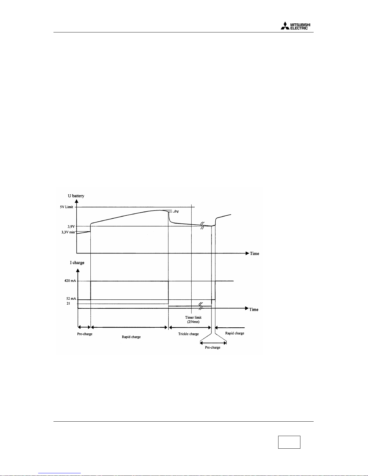
The phone transmits only if the battery is attached to it, in any configuration of power supply. When
the phone is connected to H/F adapter, DTC, AC/DC, or CLA, the battery charging circuit operates.
Battery voltage (+3.8 V) is applied via D118 or from TESTPS ( J103 pin1 ) through D124 when using
Hand Free.
The main power supply is fed to the phone either from the attached battery via the connector J101, or
from accessories :
•H/F adapter,
•Desk Top Charger DTC,
•AC/DC adapter and CLA via the external connector J103.
R120 and R121 give an internal voltage reference. If the battery voltage VBAT falls down, then
BYPASS shorts out the diode D118 through TR103 to reduce voltage drop.
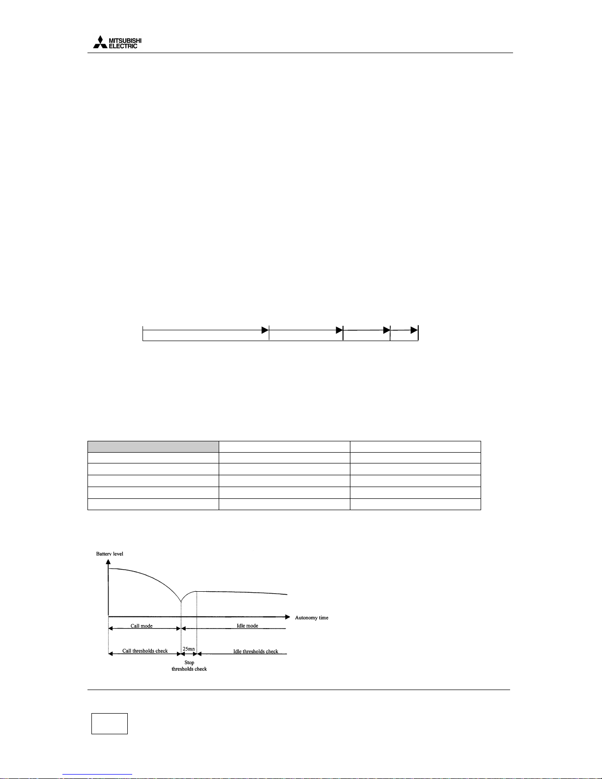
2.5 Autonomy Control.
The battery energy is displayed on the LCD by a 3 bars “battery icon” . Voltage thresholds for each
bars are calculated to have this autonomy time share out:
A 3 times 33% time shares out is not possible because of the very stable battery level between 20%
to 50% autonomy time. In addition with these bars, a ” low battery alarm” is displayed between ”1
bar” and the mobile off.
All these thresholds are programmed in EEprom by the factory and given in following thresholds
table.
Idle Mode Call Mode
Initial thresholds Battery level Battery level
3 bars →2 bars 3.86V 3.77V
2 bars →1 bars 3.71V 3.60V
1 bar →low battery alarm 3.57V 3.40V
Power off 3.46V 3.30V
Thresholds are different according to the mode, Idle mode or Call mode. Idle mode threshold are
checked by software 25 min after the end of the call.
When battery voltage is less than the threshold given in the table above, BAT_EMPTY is true.
40% 80%