manuals.online logo
Brands
  1. Home
  2. •
  3. Brands
  4. •
  5. MKS
  6. •
  7. Transducer
  8. •
  9. MKS 523210-0-0E-T User manual

MKS 523210-0-0E-T User manual

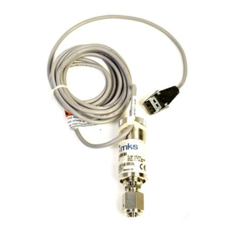
Figure 1: Series 523 Wide Range Cold Cathode
Transducer
General Description
The Series 523 Wide Range Cold Cathode Transducer is
a modular instrument consisting a cold cathode vacuum
gauge and electronics enclosure capable of measuring
vacuum pressures from 1 x 10⁻⁷ Torr to Atmosphere.
Benefits of the design include:
• Compact, convenient, cost saving vacuum
measurement
• No hot filament, eliminating filament burnout
Intended Use
The intended use of this instrument is to measure
vacuum pressure in the range of 1 x 10⁻⁷ Torr to
Atmosphere. This device is to be used only in
accordance with the instructions in this Quick Start
Guide.
Improper Use
• Removal of any factory installed components
• Modification of any factory installed components
• Removal of any labeling or warranty seals
• Use of the individual components separately from the
Series 523 Cold Cathode Transducer
• Operation of this device in any flammable gas,
condensing vapor, or liquid environment
• Operation in explosive environments
• Rotation of the magnet will void the warranty.
Warranty Information
MKS Instruments, Inc. provides an eighteen (18) month
warranty from the date of shipment for new products.
The MKS Instruments, Inc. General Terms and
Conditions of Sale provides the complete and exclusive
warranty for MKS products. This document may be
located on the MKS web site at www.mksinst.com, or
may be obtained by contacting a MKS Customer Service
Representative.
Safety Notices
These safety precautions must be observed during all
phases of installation, operation, and service of this
product. Failure to comply with these precautions or with
specific warnings elsewhere in this instruction guide
violates safety standards of design, manufacture, and
intended use of the instrument. MKS Instruments, Inc.
disclaims all liability for the customer's failure to comply
with these requirements.
These instructions do not and cannot provide for every
contingency that may arise in connection with the
installation, operation, or maintenance of this product. If
you require further assistance, contact MKS at the
address given on this instruction guide.
Safety Symbols
Figure 2: Safety Symbols on the Series
523 Wide Range Cold Cathode Transducer
High Voltage
Grounding Requirements
Strong Magnetic Field
Location of the Series 523 Cold Cathode
Transducer on the Vacuum Chamber
• Locate the transducer away from devices sensitive to
magnetic fields such as RGAs, hot cathodes, and
mag-lev turbo pumps.
• Locate the transducer where it can be easily
accessed.
• For greatest accuracy and repeatability, locate the
transducer in a stable, room-temperature
environment.Ambient temperatureshould notexceed
40 °C (104°F) operating, non-condensing, or 70 °C
(158 °F) non-operating.
• Locate the transducer away from internal and
external heat sources and in an area where ambient
temperature remains reasonably constant. Do not
mount the transducer above other equipment that
generates excessive heat.
• Do not locate the transducer directly below the
chamber which may allow sputtering particles or other
contamination to fall into the gauge.
• Do not locate the transducer near the pump, where
gauge pressure might be lower than system vacuum
pressure.
• Do not locate the transducer near a gas inlet or other
source of contamination.
• Do not locate the transducerwhere it will be exposed
to corrosive gases.
Figure 3: Dimensions of the Cold Cathode Gauge
(with NW25KF Flange)
Attach the transducer to the Vacuum
Chamber
Connect the transducer Gauge to the vacuum system
flange using the appropriate gasket and mounting
hardware.
The NW25KF style flange requires a self-centering
O-ring between mating flanges.
Attach the transducer to the mating NW-style connector
on the vacuum chamber.
Electrical Requirements and
Connections
Electrical power to the Series 523 Wide Range Cold
Cathode Transducer should be provided only by an
approved, SELV power supply that meets the input
specifications of the product, and is equipped with
reinforced insulation between the main power supply and
the output to the transducer.
1. Connect 24 Vdc to pin 4 with respect to pin 2. See
Figure 4.
Figure 4: 9-pin Electrical Connector
Figure 5: Status LED and Electrical Connector
Setup & Use of the Transducer
1. Apply 24 Vdc power to pins 4 and 2 to power the unit.
2. Verify that the LED status is Green.
3. Measure voltage across pins 3 and 7.
4. See Figure 6 to convert the voltage signal to a
pressure.
Table 1: Transducer LED Status
NOTE:
The transducer will report 10.5 Vdc and the LED will
display Yellow if plasma is OFF.
Figure 6: Analog Output of the 523 Transducer
Product Specifications
NOTE:
1. Do NOT use the Series 523 Wide Range Cold
Cathode Transducer with flammable or explosive
gases.
Sensor Replacement Procedure
1. To remove the sensor, rotate lock collar 75°
counterclockwise until full stop. Pull the sensor out of
the module. Discard the old sensor in accordance
with local ordinances.
2. Place the new sensor into the module.
Note: Do not rotate the magnet which isset at the
factory. Rotation will void the warranty.
The sensor is keyed and the module is designed to
accept the sensor only in the correct orientation.
Push on the KF25 fitting until the electrodes are
pressed into place. The sensor will now be below the
lock collar tabs.
3. Turn the lock collar 75° clockwise until full stop. The
sensor is now in place and the transducer is ready to
install on the vacuum system.
Figure 7: Sensor Replacement - p/n 523100-0E
Declaration of Conformity
Chinese Hazardous Substances
Concentration Table
Series 523
Quick Start Guide for
Series 523 Wide Range
Cold Cathode Transducer
Quick Start Guide
p/n 20002442-Rev. A
This Quick Start Guide is for use
with MKS p/n 523210-0-0E-T
and 523100-0E
General Safety Notices
Do not use this instrument to measure the
pressureof flammableorexplosivegases. Using
the transducer to measure the pressure of
flammable or explosive gases can cause a fire or
explosion resulting in severe property damage
or personal injury.
Exposing the transducer to moisture can cause
fire or electrical shock resulting in severe
property damage or personal injury. To avoid
exposing the gauge to moisture, install it in an
indoor environment. Do not install the
transducer in any outdoor environment.
To avoid measurement error or product failure
dueto overpressurization, installpressure relief
valves or rupture disks in the system if pressure
substantially exceeds 1000 Torr (1333 mbar, 133
kPa).
CAUTION
High Voltage in Product
Electrical Shock or Personal Injury
The service and repair information in this
instruction guide is for the use of Qualified
Service Personnel. To avoid possible electrical
shock or personal injury, do not perform any
servicing on this product unless you are
qualified to do so.
WARNING
High Voltage and Proper Grounding
All components of a vacuum system used with
this or any similar high voltage product must be
maintained at Earth ground for safe operation.
Be aware that grounding this product does not
guarantee that other components of the vacuum
system are maintained at Earth ground.
Verify that the vacuum port to which the
transducer is mounted is electrically grounded.
Connect power cords only to properly grounded
outlets or sources.
WARNING
Strong Magnetic Field
The magnet in the product produces strong
magnetic fields which can disturb electronic
devices like heart pacemakers, or can impair
theirfunction. Maintaina safedistanceof >10cm
between the magnet and a heart pacemaker.
Keep tools and other metallic objects away from
the magnet.
WARNING
Dimensions
in
inches
LED Color Analog Out
Vdc Condition
Green 0.5 - 9.0 Normal operation
Yellow 10.5 Above operating range
Yellow 10.5 Below operating range or waiting for
discharge to start
Parameter Specification
Measurement Range for
N2/ Air 1See note 1, below
Torr 1x10⁻⁷ Torr to Atmosphere
mbar 1.33x10⁻⁷ mbar to Atmosphere
pascal 1.33x10⁻⁵ Pa to Atmosphere
Accuracy (N2)+/- 50% (5x10⁻⁷ to 1x10⁻² Torr)
+/- 50% (Over 10 Torr)
Input power 24 Vdc, 2.5 W continuous
Weight < 400 g
Operating temperature 0 oC to +40 oC (32 oF to 104 oF) ambient,
indoor use only, ordinary protection from
moisture
Operation humidity 0 to 90%
Non-operating
temperature 0 oC to +70 oC (32 oF to 158 oF)
Mounting orientation Any
CE Compliance EMC: EN61326-1
Environmental RoHS
Materials exposed to gas Polypropylene, 304 stainless steel
Specifications and dimensions are subject to change without notice.
Service and Maintenance
If the product requires service, contact the MKS
Technical Support Department at 1-303-652-4400 for
troubleshooting help over the phone.
If the product must be returned to the factory for service,
request a Return Material Authorization (RMA) from
MKS, which can be completed at https://
www.mksinst.com/service/servicehome.aspx. Do not
return products without first obtaining an RMA. In most
cases a hazardous materials disclosure form is required.
The MKS Customer Service Representative will advise
you if the hazardous materials document is required.
When returning products to MKS, be sure to package the
products to prevent shipping damage. Damaged
returned products as a result of inadequate packaging is
the Buyer's responsibility.
Customer Service / Technical Support
MKS Pressure and Vacuum Measurement Solutions
MKS Instruments, Inc.
6450 Dry Creek Parkway
Longmont, Colorado 80503 USA
Tel: 303-652-4400
Fax: 303-652-2844
Email: [email protected]
MKS Corporate Headquarters
MKS Instruments, Inc.
2 Tech Drive, Suite 201
Andover, MA 01810 USA
Tel: 978-645-5500
Fax: 978-557-5100
Email: [email protected]
© 2017 MKS Instruments, Inc. All rights reserved.
Granville-Phillips®is a registered trademark, and mksinstTM
is a trademark of MKS Instruments, Inc. All other trademarks
and registered trademarks are the properties of their respective
owners.
Quick Start Guide p/n 20002191-Rev. A
June 2017
Template p/n DR100019-Rev. F

This manual suits for next models

1

Other MKS Transducer manuals

MKS Baratron 121A User manual

MKS

MKS Baratron 121A User manual

MKS 910 DualTrans Series Specification sheet

MKS

MKS 910 DualTrans Series Specification sheet

MKS Baratron 622A User manual

MKS

MKS Baratron 622A User manual

MKS UniMag 971 Specification sheet

MKS

MKS UniMag 971 Specification sheet

MKS UniMag 971B Specification sheet

MKS

MKS UniMag 971B Specification sheet

MKS Baratron 631D User manual

MKS

MKS Baratron 631D User manual

MKS Baratron 631F User manual

MKS

MKS Baratron 631F User manual

MKS Baratron 740C User manual

MKS

MKS Baratron 740C User manual

MKS MicroPirani 925 Series Specification sheet

MKS

MKS MicroPirani 925 Series Specification sheet

MKS 901P How to use

MKS

MKS 901P How to use

MKS MicroPirani 925 Series How to use

MKS

MKS MicroPirani 925 Series How to use

MKS Baratron 223B User manual

MKS

MKS Baratron 223B User manual

MKS 107B User manual

MKS

MKS 107B User manual

MKS MicroPirani 925 Series How to use

MKS

MKS MicroPirani 925 Series How to use

MKS Baratron 722C User manual

MKS

MKS Baratron 722C User manual

MKS 907 Series User manual

MKS

MKS 907 Series User manual

MKS 901P Specification sheet

MKS

MKS 901P Specification sheet

MKS Baratron 722A User manual

MKS

MKS Baratron 722A User manual

MKS 902B Specification sheet

MKS

MKS 902B Specification sheet

MKS 910 DualTrans Series Installation guide

MKS

MKS 910 DualTrans Series Installation guide

MKS Baratron 722B User manual

MKS

MKS Baratron 722B User manual

MKS Baratron 127A User manual

MKS

MKS Baratron 127A User manual

MKS HPS Products 999 Quattro Series User manual

MKS

MKS HPS Products 999 Quattro Series User manual

MKS 910-11000-0016 User manual

MKS

MKS 910-11000-0016 User manual

Popular Transducer manuals by other brands

HBM T40 Mounting instructions

HBM

HBM T40 Mounting instructions

Beko METPOINT PRM SP11 Instructions for installation and operation

Beko

Beko METPOINT PRM SP11 Instructions for installation and operation

turck HART IM33-11-Hi/24VDC Series manual

turck

turck HART IM33-11-Hi/24VDC Series manual

M-system HVPN instruction manual

M-system

M-system HVPN instruction manual

Balluff BTL7-S5 B-M Series Condensed guide

Balluff

Balluff BTL7-S5 B-M Series Condensed guide

Balluff Micropulse BTL5-E series user guide

Balluff

Balluff Micropulse BTL5-E series user guide

Baker Hughes Masoneilan 8000 instruction manual

Baker Hughes

Baker Hughes Masoneilan 8000 instruction manual

Setra Systems 205-2 operating instructions

Setra Systems

Setra Systems 205-2 operating instructions

Neltronics OBD-400 user manual

Neltronics

Neltronics OBD-400 user manual

Thyracont VSP63MA4 operating instructions

Thyracont

Thyracont VSP63MA4 operating instructions

TR-Electronic LMRS-27 Interface-Box ANA-I manual

TR-Electronic

TR-Electronic LMRS-27 Interface-Box ANA-I manual

TILLQUIST LQT40S user manual

TILLQUIST

TILLQUIST LQT40S user manual

Shinkawa FK-152R operating instructions

Shinkawa

Shinkawa FK-152R operating instructions

Lowrance SIMRAD Ice transducer installation guide

Lowrance

Lowrance SIMRAD Ice transducer installation guide

Phase XtalX DDQS1 user manual

Phase

Phase XtalX DDQS1 user manual

HESCH HE 5411 operating instructions

HESCH

HESCH HE 5411 operating instructions

Airmar Tilted Element B164 Owner's guide and installation instructions

Airmar

Airmar Tilted Element B164 Owner's guide and installation instructions

gtm M Series operating manual

gtm

gtm M Series operating manual

manuals.online logo
manuals.online logoBrands
  • About & Mission
  • Contact us
  • Privacy Policy
  • Terms and Conditions

Copyright 2025 Manuals.Online. All Rights Reserved.