SETTING THE CONNECTOR GUIDE
2.1 Installation
Set the press on a bench of su table he ght and
capable of support ng at least 70 kg (155 lbs). Us ng
the two (2) M4 X 12 FSHCs suppl ed w th the press,
mount the Hous ng Load Platform to the press as
shown n F gure 1-1. (See also the assembly
draw ng n Sect on 4.) There are two (2) clearance
holes n the base plate (see F g, 1-1), for 8 mm or
5/16 n. screws, f t s des red to bolt the press to the
bench. Make sure there s adequate room around
the press for the operator to load connectors and to
store w res and f n shed harnesses. Make certa n
there s adequate l ght ng.
2.2 Setu
2.2.1 Termination Height
Refer to F gure 1-1 and 2-1.
In order to nsure the connector top half s correctly
seated n the lower half and that the w res are
correctly term nated, t may necessary to adjust the
term nat on he ght. Th s s done as follows:
1. To adjust the term nat on he ght, loosen the
three (3) socket head cap screws that lock the
adaptor block to the press frame.
2. To decrease the term nat on he ght (the he ght
of the connector after term nat on) turn the
he ght adjust ng knob counterclockw se. To
ncrease the he ght, turn the knob clockw se.
3. When the des red he ght s set, t ghten the
lock ng screws. The he ght of the connector
after term nat on should be as follows:
a) 90833, 90888, 91338and 91954 ser es, he ght =
23 +0.2 / -0.1 mm.
b) 90835 and 91247 ser es, he ght = 25 +0.2 / -0.1
mm.
c) See also sheet 4 of the appl cat on
spec f cat ons #AS-99033-0004.
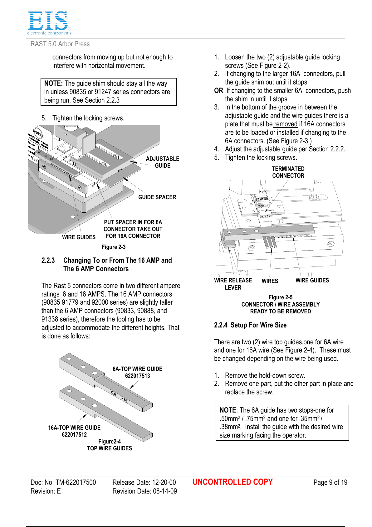
2.2.2 Adjusting for Connector Size
The Rast 5 connectors come n var ous c rcu t s zes
from 1 to 12, and also n f ve types, two (2) of wh ch
(90835 and 91247 Ser es) are 16A connectors and
are sl ghtly taller and requ re the removal of a sh m.
See Sect on 2.2.3 for deta ls. Adjust ng for c rcu t
s ze s as follows:
1. Place a stack of connectors of the correct s ze
on the connector support and sl de t forward
unt l t s between the adjustable gu de block and
the f xed gu de block.
2. Push t up aga nst the f xed gu de block.
3. Loosen the two (2) lock ng screws (See F gure
2-2).
4. Sl de the adjustable gu de block toward the
connector unt l the connector stack can be sl d
between the gu des w th no not ceable s de play.
The connector holdown plates on both s des
should be n far enough that they hold the