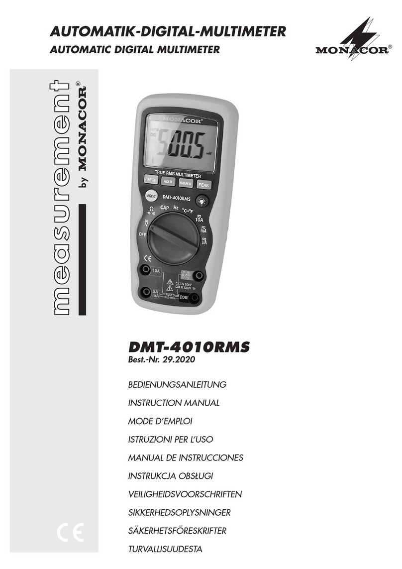
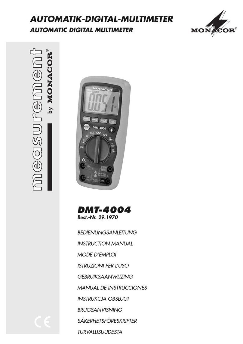
Monacor DMT-1005 User manual

®
DMT-1005
Best.-Nr. 29.1690
Bedienungsanleitung
Instruction manual
Mode d’emploi
Istruzioni per l’uso
Gebruiksaanwijzing
Handleiding
Manual de instrucciones
Manual de instruções
Brugsanvisning
Bruksanvisning
Digital-Multimeter

Bitte lesen Sie vor
dem Gebrauch
diese Anleitung.
Der deutsche Text
beginnt auf der
Seite 4.
D
A
CH
Please read these
instructions before
use.
The English text
starts on page 12.
GB
Vous prions de lire
cette notice.
La version fran-
çaise commence à
la page 20.
F
B
CH
Vi preghiamo di
leggere le presenti
istruzioni prima
dell'uso.
Il testo italiano co-
mincia a pagina 28.
I
Wij raden u aan
deze handleiding
goed door te lezen
voor u het appa-
raat in gebruik
neemt. De Neder-
landse tekst begint
op pagina 36.
NL
B
E
Por favor leia
estas instruçoes
antes de usar o
equipamento.
O texto em portu-
guês começa na
página 52.
P
DK
Läs igenom bruk-
sanvisningen för
att undvika fel
och/eller skador på
densamma. Den
svenska texten
finns på sidan 68.
S
Por favor, lee aten-
tamente las
instrucciones de
uso. La versión en
Español se encu-
entra en la página
44.
Læs hele brugsan-
visningen igennem
før brug.
Den danske tekst
starter på side 60.
2
®

3
10A DC
10A MAX
VΩmA
OFF
750V AC
1000V DC
200mA MAX
COM
B
500V MAX
E
B
E
C
NPN PNP
e
c
b
e
1000 750
200
200
20
2000
m
200
m
V V~
A
200µ
2000
µ
20
m
200
m
10A
Ω
200
2000
20k
200k
2000k
hFE
DMT-1005
®
1
6
2
3
5
4

Bitte klappen Sie die Seite 3 heraus. Sie
sehen dann immer die beschriebenen
Bedienelemente und Anschlüsse.
Inhalt
1 Übersicht der Bedienelemente und
Anschlüsse . . . . . . . . . . . . . . . . . . . . . 4
2 Hinweise für den sicheren Betrieb . . . . 5
3 Verwendungsmöglichkeiten . . . . . . . . . 6
4 Inbetriebnahme . . . . . . . . . . . . . . . . . . 6
5 Messungen durchführen . . . . . . . . . . . 6
5.1 Spannungsmessung . . . . . . . . . . . . . . 7
5.2 Gleichstrommessung . . . . . . . . . . . . . . 7
5.3 Widerstandsmessung . . . . . . . . . . . . . 8
5.4 Stromverstärkung bei Transistoren . . . 8
5.5 Durchlaßspannung bei Dioden . . . . . . 9
6 Batterie oder Sicherung austauschen . 9
7 Technische Daten . . . . . . . . . . . . . . . 10
1 Übersicht der Bedienelemen-
te und Anschlüsse
1Display
2Bereichsschalter
3Steckanschlüsse zur Messung der Strom-
verstärkung bei Transistoren
4Anschlußbuchse „10ADC” für die rote
Meßleitung (Pluspol) zum Messen im
10-A-Gleichstrombereich
5Anschlußbuchse „VΩmA“ für die rote
Meßleitung (Pluspol) zum Messen in
allen Bereichen, außer im 10-A-Gleich-
strombereich
6Anschlußbuchse „COM“ für die schwarze
Meßleitung (Minuspol)
D
A
CH
4

2 Hinweise für den sicheren
Gebrauch
Dieses Gerät entspricht der Richtlinie für elek-
tromagnetische Verträglichkeit 89/336/EWG
und der Niederspannungsrichtlinie 73/23/
EWG.
Mit diesem Instrument können lebensge-
fährlich hohe Spannungen gemessen wer-
den. Bei Messungen von Spannungen ab
42V ist besondere Sorgfalt geboten. Ach-
ten Sie stets auf den einwandfreien Zustand
der Meßleitungen. Beschädigte Meßleitun-
gen müssen ausgetauscht werden.
Beachten Sie für den Betrieb auch unbedingt
die folgenden Punkte:
●Das Gerät ist nur zur Verwendung in Räu-
men geeignet.
●Schützen Sie das Gerät vor Feuchtigkeit
und Hitze (zulässiger Einsatztemperatur-
bereich 0–40°C).
●Wird das Gerät zweckentfremdet, falsch
bedient bzw. angeschlossen, überlastet
oder nicht fachgerecht repariert, kann für
eventuelle Schäden keine Haftung über-
nommen werden.
●Für die Reinigung nur ein trockenes, wei-
ches Tuch verwenden, auf keinen Fall
Chemikalien oder Wasser.
●Soll das Gerät endgültig aus dem Betrieb
genommen werden, übergeben Sie es zur
Entsorgung einem örtlichen Recyclingbe-
trieb.
D
A
CH
5

3 Verwendungsmöglichkeiten
Dieses Digital-Multimeter dient zur Messung
von Gleich- und Wechselspannungen, Gleich-
strömen sowie Widerständen.Außerdem läßt
sich bei Dioden die Durchlaßspannung mes-
sen und bei Transistoren die Stromverstär-
kung (hFE).
4 Inbetriebnahme
1) Den Drehschalter (2) auf den gewünsch-
ten Meßbereich stellen.
2) Im Display wird eine Anzeige sichtbar.
Wenn nicht, muß eine 9-V-Batterie einge-
setzt werden. Erscheint im Display das
Symbol , die Batterie auswechseln —
siehe Kapitel 6 „Batterie oder Sicherung
austauschen”.
3) Nach dem Betrieb immer das Gerät mit
dem Drehschalter ausschalten (Position
„OFF”), sonst wird die Batterie unnötig ver-
braucht.
5 Messungen durchführen
Die schwarze Meßleitung immer in die
schwarze Buchse „COM“ (6) stecken und die
rote Meßleitung in die mittlere Buchse „VΩmA“
(5) bzw. bei Messungen im 10-A-Gleichstrom-
bereich in die obere Buchse „10ADC“ (4).
Für eine hohe Genauigkeit immer den
kleinstmöglichen Meßbereich wählen (z.B.
15V im 20-V-Bereich messen und nicht im
200-V-Bereich). Ist ein Meßbereich über-
schritten, signalisiert das Gerät „1“ oder „
-
1“.
In diesem Fall den nächstgrößeren Bereich
wählen.
D
A
CH
6

D
A
CH
7
5.1 Spannungsmessung
●Bei Messungen ab 42V besonders sorg-
fältig vorgehen. Auf keinen Fall das Meß-
objekt oder die Meßspitzen berühren.
●Die maximal zu messende Spannung darf
1000V oder 750V~ nicht überschreiten.
Andernfalls besteht für den Benutzer
Lebensgefahr!
1) Die rote Meßleitung muß an der Buchse
„VΩmA“ (5) angeschlossen sein.Auf keinen
Fall versehentlich die Buchse „10ADC“ (4)
verwenden! Das Meßgerät und die Span-
nungsquelle können beschädigt werden.
2) Bei Wechselspannungen den Bereichs-
schalter (2) in einen der Bereiche „V~“ stel-
len, bei Gleichspannungen in einen der
Bereiche „V “. In den Bereichen 1000V
und 750V~ signalisiert das Display „HV“
(High Voltage– hohe Spannung).
3) Die Meßspitzen an das Meßobjekt halten,
und auf dem Display den Meßwert ablesen.
4) Liegt bei Gleichspannungsmessungen an
der roten Meßspitze der Minuspol und an
der schwarzen Meßspitze der Pluspol,
erscheint im Display vor dem Meßwert ein
Minuszeichen.
5.2 Gleichstrommessung
●Der maximal zu messende Gleichstrom
darf 10A nicht überschreiten.
●Der 10-A-Meßstromkreis ist nicht abgesi-
chert. Hier ist besondere Vorsicht geboten.
●Steht der Bereichsschalter (2) auf einem
Gleichstrombereich, auf keinen Fall eine
Spannung auf das Meßgerät geben. Das
Meßgerät und die Spannungsquelle kön-
nen beschädigt werden.
1) Bei Gleichströmen zwischen 200mA und
10A die rote Meßleitung in die Buchse
„10ADC“ (4) stecken, und den Bereichs-
schalter (2) in die Position „10A “ drehen.
Bei Gleichströmen bis 200mA die rote
Meßleitung in die Buchse „VΩmA“ (5)
stecken, und den Bereichsschalter in
einen der Bereiche „A “ drehen.
2) Den zu messenden Stromkreis auftren-
nen. Die rote Meßspitze mit dem positiven
Punkt verbinden und die schwarze mit
dem negativen Punkt. Bei umgekehrter
Polarität erscheint im Display vor dem
Meßwert ein Minuszeichen.
5.3 Widerstandsmessung
●Das Gerät ist bis 250V /~ überlastge-
schützt. Trotzdem nicht innerhalb einer
Schaltung messen, wenn diese unter
Spannung steht.
●Einen Widerstand immer separat messen,
sonst ist die Messung falsch. Dazu muß
er ggf. aus der Schaltung herausgelötet
werden.
1) Die rote Meßleitung muß an der Buchse
„VΩmA“ (5) angeschlossen sein.
2) Den Bereichsschalter (2) in einen der
Bereiche „Ω“ stellen.
3) Die Meßspitzen an den Widerstand bzw.
an die entsprechenden Meßpunkte halten.
5.4 Stromverstärkung bei
Transistoren
1) Den Transistor seinen Anschlüssen ent-
sprechend (E, B, C) in die Steckan-
schlüsse (3) einsetzen. Für NPN-Typen
D
A
CH
8

die grün beschrifteten Kontakte verwen-
den und für PNP-Typen die schwarz
beschrifteten.
2) Den Drehschalter (2) in die Position „hFE“
stellen.
3) Das Display zeigt die Stromverstärkung
(max. 1000) bei einem Basisstrom (IB) von
ca. 10µAund einer Kollektor-Emitter-Span-
nung (UCE) von ca. 2,8V an.
5.5 Durchlaßspannung bei Dioden
1) Die rote Meßleitung muß an der Buchse
„VΩmA“ (5) angeschlossen sein.
2) Den Drehschalter (2) in die Position
stellen.
3) Die Kathode der Diode an die schwarze
Meßspitze halten und die Anode an die
rote Meßspitze.
4) Das Display zeigt die Durchlaßspannung
bei einem Teststrom von 1,5mA in mV an.
Bei einer Anzeige von 0V hat die Diode
den Kurzschluß.
Bei der Anzeige „1“ ist die Diode unterbro-
chen oder in Sperrichtung angeschlossen
(Diode umpolen).
6 Batterie oder Sicherung aus-
tauschen
●Vor dem Öffnen des Gerätes unbedingt
die Meßleitungen von den Meßpunkten
der Schaltung entfernen, um jegliche
Gefahr eines elektrischen Schlages zu
vermeiden.
●Betreiben Sie das Gerät niemals im geöff-
neten Zustand.
D
A
CH
9

a. Wird im Display das Symbol ange-
zeigt, muß die 9-V-Batterie ausgetauscht
werden.
b. Ist keine Messung in den Gleichstrombe-
reichen 200µA–200mA möglich, die
Sicherung überprüfen und ggf. durch eine
gleichen Typs (0,2A, flink) ersetzen.
Zum Austausch auf der Geräterückseite die
beiden Schrauben entfernen, und die untere
Gehäuseschale abnehmen. Nach dem Aus-
tausch die Gehäuseschale festschrauben.
Erst dann das Instrument wieder in Betrieb
nehmen.
7 Technische Daten
Allgemein
Anzeige: . . . . . . . . . . . . . 12-mm-LCD,
31/2stellig
Stromversorgung: . . . . . . 9-V-Batterie
Einsatzbereich: . . . . . . . . 0–40°C, < 75%
Luftfeuchtigkeit
Abmessungen (BxHxT): 70x27x125mm
Gewicht: . . . . . . . . . . . . . 150g
Gleichspannung
Meßbereiche: . . . . . . . . . 200mV,
2V, 20V, 200V,
1000V
Genauigkeit*
200mV–200V: . . . . . ±(0,5% +2Digits)
1000V: . . . . . . . . . . . . ±(0,8% +2Digits)
Eingangswiderstand: . . . 1MΩ
D
A
CH
10

Wechselspannung
Meßbereiche: . . . . . . . . . 200V, 750V
Genauigkeit* . . . . . . . . . .
±(1,2%+10Digits)
Frequenzbereich: . . . . . . 45–400Hz
Gleichstrom
Meßbereiche: . . . . . . . . . 200µA,
2mA, 20mA,
200mA, 10A
Genauigkeit*
200µA–20mA: . . . . . ±(1,0% +2Digits)
200mA: . . . . . . . . . . . ±(1,2% +2Digits)
10A: . . . . . . . . . . . . . . ±(2,0% +2Digits)
Widerstand
Meßbereiche: . . . . . . . . . 200Ω, 2kΩ,
20kΩ, 200kΩ,
2MΩ
Genauigkeit*
200Ω–200kΩ: . . . . . . ±(0,8% +2Digits)
2MΩ: . . . . . . . . . . . . . ±(1,0% +2Digits)
Transistortest
Anzeige: . . . . . . . . . . . . . Stromverstärkung
(hFE) 0–1000 bei
UCE 2,8V, IB10µA
Diodentest
Anzeige: . . . . . . . . . . . . . Durchlaßspan-
nung bei 1,5mA
Teststrom
*bei 23°C, ±5°C
Laut Angaben des Herstellers.
Änderungen vorbehalten.
D
A
CH
11

Please unfold page 3. Then you can
always see the operating elements and
connections described.
Contents
1 Operating Elements and
Connections . . . . . . . . . . . . . . . . . . . 12
2 Safety Notes . . . . . . . . . . . . . . . . . . . 13
3 Applications . . . . . . . . . . . . . . . . . . . . 13
4 Setting into Operation . . . . . . . . . . . . 14
5 Carrying out Measurements . . . . . . . 14
5.1 Voltage measurements . . . . . . . . . . . 14
5.2 Direct current measurements . . . . . . 15
5.3 Resistance measurements . . . . . . . . 16
5.4 Current amplification with transistors 16
5.5 Forward voltages with diodes . . . . . . 17
6 Replacement of Battery or Fuse . . . . 17
7 Specifications . . . . . . . . . . . . . . . . . . 18
1 Operating Elements and
Connections
1Display
2Range switch
3Plug-in connections to measure the cur-
rent amplification with transistors
4Jack “10ADC” for the red test lead (posi-
tive pole) to measure in the 10ADC range
5Jack “VΩmA” for the red test lead (posi-
tive pole) to measure in all ranges except
in the 10ADC range
6Jack “COM” for the black test lead (nega-
tive pole)
GB
12

2 Safety Notes
This appliance corresponds to the directive
for electromagnetic compatibility 89/336/
EEC and the low voltage directive
73/23/EEC.
With this unit very lethal high voltages can
be measured. Be especially careful with
voltage measurements above 42V. The
test leads must always be perfectly insula-
ted. Damaged test leads must be replaced.
For operation also observe in any case the
following:
●The unit is only suitable for indoor use.
●Protect the unit from humidity and heat
(permissible ambient temperature range
0–40°C).
●If the unit is used for purposes other than
originally intended, if it is overloaded or
operated, connected or repaired in the
wrong way, there is no liability for possible
damage.
●Only use a dry, soft cloth for cleaning, by
no means chemicals or water.
●If the unit is to be put out of operation defin-
itively, bring it to a local recycling plant for
disposal.
3 Applications
This digital multimeter serves for measuring
DC and AC voltages, DC currents as well as
resistances. Furthermore, the forward volt-
age of diodes and the current amplification of
transistors (hFE) can be measured.
GB
13

4 Setting into Operation
1) Set the rotary switch (2) to the desired
measuring range.
2) The display shows an indication. If not, a
9V battery must be inserted. If the symbol
is displayed, replace the battery — see
chapter 6 “Replacement of battery or fuse”.
3) After the operation always switch off the
unit with the rotary switch (position “OFF”),
otherwise the battery will be exhausted
unnecessarily.
5 Carrying out Measurements
Always plug the black test lead into the black
jack “COM” (6) and the red test lead into the
central jack “VΩmA” (5) resp. with measure-
ments in the 10ADC range into the upper
jack “10ADC” (4).
For a high accuracy always choose the
lowest possible measuring range (e.g. 15V
in the 20V range and not in the 200V range).
If a measuring range has been exceeded, the
unit signalizes “1” or “
-
1”. In this case choose
the next higher range.
5.1 Voltage measurements
●For measurements from 42V on be espe-
cially careful. By no means touch the
object to be measured or the test tips.
●The voltage to be measured at maximum
must not exceed 1000V or 750V~.
Otherwise there is danger of life for the
user!
1) The red test lead must be connected to the
jack “VΩmA” (5). By no means use the
GB
14

jack “10ADC” (4) accidentally! The meter
and the voltage source may be damaged.
2) With alternating voltages set the range
switch (2) to one of the ranges “V~”, with
direct voltages to one of the ranges “V ”.
In the ranges 1000V and 750V~ the
display signalizes “HV” (= high voltage).
3) Hold the test tips at the object to the
measured and read the measuring value
from the display.
4) If with direct voltage measurements the
negative pole is at the red test tip and the
positive pole at the black test tip, a minus
sign is displayed before the measuring
value.
5.2 Direct current measurement
●The direct current to be measured at maxi-
mum must not exceed 10A.
●The 10A measuring current circuit is not
fused. Be especially careful in this case.
●If the range switch (2) is set to a direct cur-
rent range, do not feed any voltage to the
meter. The meter and the voltage source
may be damaged.
1) For direct currents between 200mA and
10A plug the red test lead into the jack
“10ADC” (4), and turn the range switch (2)
into position “10A ”.
With direct currents up to 200 mA plug
the red test lead into jack “VΩmA” (5), and
turn the range switch to one of the ranges
"A ".
2) Open up the current circuit to be meas-
ured. Connect the red test tip with the posi-
tive point and the black with the negative
GB
15

point. With reverse polarity a minus sign is
displayed before the measuring value.
5.3 Resistance measurement
●The meter is protected against overload
up to 250V /~. In spite of this, do not
measure within a circuit if it carries a volt-
age.
●Always measure a resistor separately,
otherwise the measurement will be wrong.
For this it must be soldered out of the cir-
cuit, if necessary.
1) The red test lead must be connected to the
jack “VΩmA” (5).
2) Set the range switch (2) into one of the
ranges “Ω”.
3) Hold the test tips at the resistor resp. at the
corresponding measuring points.
5.4 Current amplification with
transistors
1) Insert the transistor according to its con-
nections (E, B, C) into the plug connec-
tions (3). For NPN types use the contacts
with green lettering, for PNP types the
contacts with black lettering.
2) Set the rotary switch (2) to position “hFE”.
3) The display shows the current amplifica-
tion (max. 1000) for a basic current (IB) of
approx. 10µA and a collector-emitter volt-
age (UCE) of approx. 2.8V.
5.5 Forward voltage with diodes
1) The red test lead must be connected to
jack “VΩmA” (5).
2) Set the rotary switch (2) to position .
GB
16

3) Hold the cathode of the diode to the black
test tip and the anode to the red test tip.
4) The display shows the forward voltage
with a test current of 1.5mA in mV.
With a display of 0V the diode has a short-
circuit.
With the display “1” the diode is interrupted
or connected in reverse direction (change
the polarity of the diode).
6 Replacement of Battery or
Fuse
●Prior to opening of the unit in any case
remove the test leads from the measuring
points of the circuit to prevent any danger
of an electric stroke.
●Never operate the unit if it has been
opened.
a. If the display shows symbol , the 9V
battery must be replaced.
b. If no measurement can be carried out in
the direct current range 200µA–200mA,
check the fuse and replace it by one of the
same type (0.2A, quick-acting), if neces-
sary.
For the replacement remove both screws at
the rear plate of the unit and take off the lower
housing shell. After the replacement tighten
the housing shell by screws. Only then take
the meter into operation again.
GB
17

7 Specifications
General
Display: . . . . . . . . . . . . . . 12mm LCD,
31/2digits
Power supply: . . . . . . . . . 9V battery
Operating range: . . . . . . 0–40°C, < 75%
humidity
Dimensions (W x H x D): 70 x 27 x 125mm
Weight: . . . . . . . . . . . . . . 150g
DC voltage
Measuring ranges: . . . . . 200mV,
2V,20V, 200V,
1000V
Accuracy*
200mV–200V: . . . . . ±(0.5% + 2 digits)
1000V: . . . . . . . . . . . . ±(0.8% + 2 digits)
Input resistance: . . . . . . . 1MΩ
AC voltage
Measuring ranges: . . . . . 200V, 750V
Accuracy*: . . . . . . . . . . .
±(1.2% + 10digits)
Frequency range: . . . . . . 45–400Hz
DC current
Measuring ranges: . . . . . 200µA,
2mA, 20mA
200mA, 10A
Accuracy*:
200µA–20mA: . . . . . ±(1.0% + 2 digits)
200mA: . . . . . . . . . . . ±(1.2% + 2 digits)
10A: . . . . . . . . . . . . . . ±(2.0% + 2 digits)
GB
18

Resistance
Measuring ranges: . . . . . 200Ω, 2kΩ
20kΩ, 200kΩ
2MΩ
Accuracy*
200Ω–200kΩ: . . . . . . ±(0.8% + 2 digits)
2MΩ: . . . . . . . . . . . . . ±(1.0% + 2 digits)
Transistor test
Display: . . . . . . . . . . . . . . current amplifica-
tion (hFE) 0–1000
with UCE 2.8V,
IB10µA
Diode test
Display: . . . . . . . . . . . . . . forward voltage
with 1.5mA test
current
*at 23°C, ±5°C
According to the manufacturer.
Subject to change.
GB
19

Ouvrez le présent livret page 3 de manière à
visualiser les éléments et branchements.
1 Table des matières
1 Eléments et branchements . . . . . . . . 20
2 Conseils d’utilisation . . . . . . . . . . . . . 21
3 Possibilités d’utilisation . . . . . . . . . . . 21
4 Mise en service . . . . . . . . . . . . . . . . . 22
5 Mesures . . . . . . . . . . . . . . . . . . . . . . . 22
5.1 Mesures de tension . . . . . . . . . . . . . . 22
5.2 Mesures de courant continu . . . . . . . 23
5.3 Mesures de résistance . . . . . . . . . . . 24
5.4 Amplification de courant pour des
transistors . . . . . . . . . . . . . . . . . . . . . 24
5.5 Tension de passage pour des diodes 25
6 Remplacement de la batterie
et du fusible . . . . . . . . . . . . . . . . . . . . 25
7 Caractéristiques techniques . . . . . . . 26
1 Eléments et branchements
1Affichage
2Sélecteur
3Fiche pour mesurer l’amplification de
courant pour des transistors
4Prise “10ADC” pour le cordon rouge
(pôle plus): mesure dans la plage 10A
DC
5Prise “VΩmA” pour le cordon rouge (pôle
plus): mesure dans toutes les plages
excepté la plage 10A DC
6Prise “COM” pour le cordon noir (pôle
moins)
20
F
B
CH
This manual suits for next models
1
Table of contents
Languages:
Other Monacor Multimeter manuals

Monacor
Monacor DMT-2050 User manual

Monacor
Monacor DMT-4010RMS User manual

Monacor
Monacor DMT-4004 User manual

Monacor
Monacor DMT-3060 User manual

Monacor
Monacor DMT-3050 User manual

Monacor
Monacor DMT-3090RS User manual

Monacor
Monacor DMT-2004 User manual

Monacor
Monacor DMT-1050 User manual

Monacor
Monacor MT-300 User manual

Monacor
Monacor DMT-1020 User manual