Monacor DMT-4004 User manual

DMT-4004
Best.-Nr. 29.1970
AUTOMATIK-DIGITAL-MULTIMETER
AUTOMATIC DIGITAL MULTIMETER
BEDIENUNGSANLEITUNG
INSTRUCTION MANUAL
MODE D’EMPLOI
ISTRUZIONI PER L’USO
GEBRUIKSAANWIJZING
MANUAL DE INSTRUCCIONES
INSTRUKCJA OBSŁUGI
BRUGSANVISNING
SÄKERHETSFÖRESKRIFTER
TURVALLISUUDESTA

2
Bevor Sie einschalten …
Wir wünschen Ihnen viel Spaß mit
Ihrem neuen Gerät von MONACOR.
Bitte lesen Sie diese Bedienungsan-
leitung vor dem Betrieb gründlich
durch und heben Sie sie für ein spä-
teres Nachlesen auf.
Der deutsche Text beginnt auf der
Seite 4.
Avant toute installation …
Nous vous souhaitons beaucoup de
plaisir à utiliser votre nouvel appareil
MONACOR. Veuillez lire la présente
notice avec attention avant le fonc-
tionnement et conservez-la pour pou-
voir vous y reporter ultérieurement.
La version française se trouve
page 20.
Voor u inschakelt …
Wij wensen u veel plezier met uw
nieuwe apparaat van MONACOR.
Lees deze bedieningshandleiding
grondig door, alvorens het apparaat
in gebruik te nemen, en bewaar ze
voor latere raadpleging.
De (Nederlandstalige) tekst vindt u
op pagina 36.
Przed włączeniem …
Życzymy przyjemnej pracy z urzą-
dzeniem firmy MONACOR. Przed
rozpoczęciem użytkowania, prosimy
zapoznać się z niniejszą instrukcją
obsługi, a następnie zachować ją do
wglądu.
Polski tekst zaczyna się na stronie 52.
Innan användning …
Vi hoppas att du skall bli nöjd med
din nya MONACOR enhet. Vänligen
läs manualen noga innan första an-
vändning och behåll dessa för fram-
tida bruk.
Säkerhetsföreskrifterna återfinns på
sidan 68.
D
A
CH
F
B
CH
NL
PL
S
GB
I
E
DK
Before you switch on …
We hope you will enjoy using your
new MONACOR unit. Please read
these operating instructions carefully
prior to operation and keep them for
later reference.
The English test starts on page 12.
Prima di accendere …
Vi auguriamo buon divertimento
con il vostro nuovo strumento di
MONACOR. Vi preghiamo di leggere
attentamente le presenti istruzioni
prima della messa in funzione e di
conservarle per un uso futuro.
Il testo italiano inizia a pagina 28.
Antes de la conexión …
Esperamos que disfrute de su nuevo
aparato MONACOR. Lea atenta-
mente las instrucciones de funciona-
miento antes de utilizar el aparato y
guárdelas para usos posteriores.
La versión española empieza en la
página 44.
Før du tænder ...
Vi håber, at du vil få glæde af at bruge
dit nye produkt fra MONACOR. Læs
venligst nærværende brugsanvisning
omhyggeligt igennem, før produktet
tages i brug; og gem brugsanvisnin-
gen til senere brug.
Den danske tekst starter på side 60.
B
FIN Ennen kuin käynnistät
laitteen ...
Toivottavasti uusi MONACOR yleis-
mittari miellyttää sinua. Ole hyvä ja lue
turvallisuusohjeet huolellisesti ennen
laitteen käyttöä ja säilytä käyttöohjeet
myöhempää tarkastelua varten.
Löydät turvallisuusohjeet sivulta 69.

3
RANGE
Hz % HOLD REL
MODE
CAP
OFF
Ω
Hz
Hz
µA
mA
10A
Hz
Hz%
Hz
µA
mA
10A
COM
V
CAP Hz%
CAT IV 600V
CAT III 1000V
FUSED
MAX. 400mA
B
Auto
mV
DC
7
6
8
9
1
2
3
4
5
10
11
12
13

Inhalt
1 Übersicht der Bedienelemente
und Anschlüsse . . . . . . . . . . . . . . . . . 4
2 Hinweise für den sicheren Gebrauch 5
3 Verwendungsmöglichkeiten . . . . . . . 5
4 Inbetriebnahme . . . . . . . . . . . . . . . . . . 5
4.1 Batterie einsetzen oder wechseln . . . . . 5
4.2 Aufkleber ACHTUNG! anbringen . . . . . 6
4.3 Messleitungen anschließen . . . . . . . . . 6
5 Messungen durchführen . . . . . . . . . . 6
5.1 Spannungsmessung . . . . . . . . . . . . . . . 6
5.2 Strommessung . . . . . . . . . . . . . . . . . . . 7
5.3 Widerstandsmessung . . . . . . . . . . . . . . 7
5.4 Durchgangssummer . . . . . . . . . . . . . . . 7
5.5 Diodenprüfung . . . . . . . . . . . . . . . . . . . 8
5.6 Kapazitätsmessung . . . . . . . . . . . . . . . 8
5.7 Frequenzmessung . . . . . . . . . . . . . . . . 8
5.8 Messung des Tastverhältnisses . . . . . . 8
6 Zusätzliche Funktionen . . . . . . . . . . . 9
6.1 Manuelle Bereichswahl . . . . . . . . . . . . . 9
6.2 Messwert festhalten . . . . . . . . . . . . . . . 9
6.3 Relativwertmessung . . . . . . . . . . . . . . . 9
7 Sicherungen ersetzen . . . . . . . . . . . . 9
8 Technische Daten . . . . . . . . . . . . . . . 10
Bitte klappen Sie die Seite 3 heraus. Sie
sehen dann immer die beschriebenen Be-
dienelemente und Anschlüsse.
1 Übersicht der Bedien-
elemente und Anschlüsse
1Taste RANGE zur manuellen Bereichswahl
2Taste Hz% zum Umschalten zwischen Fre-
quenzmessung und Messung des Tastver-
hältnisses
Steht der Drehschalter (10) auf Strom-
oder Spannungsmessung, kann mit der
Taste Hz% auf Frequenzmessung und
Messung des Tastverhältnisses umge-
schaltet werden sowie wieder zurück auf
Strom- bzw. Spannungsmessung
3Taste MODE zum Umschalten der Mess-
funktion (z. B. Gleich- oder Wechselstrom-
messung, Diodentest oder Durchgangs-
prüfung)
4Buchse 10 A für die rote Messleitung zur
Strommessung 400 mA – 10 A
5Buchse µA/mA für die rote Messleitung zur
Strommessung bis max. 400 mA
6Display
7Taste HOLD zum Festhalten eines Mess-
wertes
8Taste REL für die Relativwertmessung
9Taste für die Displaybeleuchtung:
Zum Einschalten die Taste 2 Sek. gedrückt
halten, zum Ausschalten die Taste kurz be-
tätigen.
10 Drehschalter zum Wählen der Messfunktion
11 Buchse V Ω CAP Hz% für die rote Mess-
leitung für alle Messungen außer Strom-
messungen
12 Buchse COM für die schwarze Messleitung
13 Abdeckhülse (2 Stück): Beim Betrieb im
Außenbereich müssen diese in die beiden
unbenutzten Messbuchsen (4, 5, 11) ge-
steckt werden, damit das Gerät nach der
Schutzklasse IP 67 geschützt ist.
D
A
CH
4

2 Hinweise für den
sicheren Gebrauch
Das Gerät entspricht allen erforderlichen Richt-
linien der EU und ist deshalb mit gekenn-
zeichnet.
Beachten Sie auch unbedingt die folgenden
Punkte:
Bei Verwendung der Abdeckhülsen (13) ist
das Gerät nach IP 67 geschützt und kann
auch im Außenbereich verwendet werden.
Schützen Sie es jedoch vor großer Kälte
und Hitze (zulässiger Einsatztemperaturbe-
reich 0 – 50 °C).
Verwenden Sie zum Säubern des Gehäu-
ses nur ein weiches, ggf. leicht angefeuch-
tetes Tuch, auf keinen Fall Chemikalien
oder scheuernde Mittel.
Werden die geltenden Sicherheitsvorschrif-
ten beim Umgang mit Spannungen ab 42 V
nicht eingehalten oder wird das Gerät
zweckentfremdet, falsch angeschlossen,
nicht richtig bedient, überlastet oder nicht
fachgerecht repariert, kann keine Haftung
für daraus resultierende Sach- oder Perso-
nenschäden und keine Garantie für das
Gerät übernommen werden.
3 Verwendungsmöglichkeiten
Dieses Automatik-Digital-Multimeter mit einem
29-mm-LC-Display (Anzeige bis 4000) dient
zur Messung von:
–Spannungen bis 1000 V /~
–Strömen bis 10 A /~
–Frequenzen bis 10 MHz
–Widerständen bis 40 MΩ
–Kapazitäten bis 200 µF
Außerdem lässt sich das Tastverhältnis von
elektrischen Signalen und die Durchlass-
spannung von Dioden messen. Zur Durch-
gangsprüfung ist ein Summer vorhanden.
4 Inbetriebnahme
1) Zum Einschalten des Instruments den Dreh-
schalter (10) von der Position OFF auf die
gewünschte Funktion drehen. Sollte im Dis-
play (6) keine Anzeige erscheinen, eine Bat-
terie einsetzen (Kapitel 4.1).
2) Den Aufstellbügel auf der Rückseite ggf. für
eine bessere Ableseposition herausklappen.
3) Nach dem Betrieb den Drehschalter in die
Position OFF stellen.
Das Gerät schaltet sich aber auch auto-
matisch aus, wenn es 15 Minuten lang nicht
benutzt wird. Eine Minute vor dem automa-
tischen Ausschalten ertönen 5 kurze Sig-
nale und beim Ausschalten ein längerer
Ton. Zum erneuten Einschalten eine Taste
oder den Drehschalter betätigen.
4.1 Batterie einsetzen oder wechseln
Erscheint nach dem Einschalten keine Anzeige
im Display (6) oder wird durch das Symbol
links im Display eine verbrauchte Batterie an-
gezeigt, eine 9-V-Blockbatterie einsetzen bzw.
die Batterie wechseln.
1) Auf der Rückseite den Aufstellbügel hoch-
klappen und die beiden mittleren Schrauben
für den Batteriefachdeckel entfernen.
2) Den Deckel abnehmen und eine 9-V-Block-
batterie, wie im Fach angegeben, einsetzen.
3) Das Batteriefach wieder schließen.
Wird das Gerät längere Zeit nicht gebraucht,
sollte die Batterie herausgenommen werden.
So lassen sich mögliche Schäden am Gerät
beim Auslaufen der Batterie vermeiden.
Soll das Gerät endgültig aus dem Be-
trieb genommen werden, übergeben
Sie es zur umweltgerechten Entsor-
gung einem örtlichen Recyclingbetrieb.
Werfen Sie verbrauchte Batterien nicht in den
Hausmüll, sondern geben Sie sie nur in den
Sondermüll (z. B. Sammelbehälter bei Ihrem
Einzelhändler).
WARNUNG Mit diesem Gerät können lebens-
gefährliche Spannungen gemes-
sen werden. Bei Messungen von
Spannungen ab 42 V ist beson-
dere Vorsicht geboten!
1. Tragen Sie Sicherheitshandschuhe zum
Schutz gegen Stromschläge.
2. Achten Sie beim Anlegen der Messspitzen
darauf, dass Ihre Finger sich hinter dem
Abrutschschutz befinden.
3. Bei Schäden am Messgerät oder an den
Messleitungen keine Messung vornehmen.
Beschädigte Messleitungen müssen durch
Originalmessleitungen ersetzt werden.
D
A
CH
5

4.2 Aufkleber ACHTUNG! anbringen
Dem Gerät liegen Aufkleber
mit wichtigen Hinweisen in
acht Sprachen bei. Kleben
Sie die Hinweise in Ihrer Lan-
desprache auf das vorgese-
hene Feld des Batteriefach-
deckels!
4.3 Messleitungen anschließen
Das Instrument ist mit vier Messbuchsen aus-
gestattet:
1. Die Buchse COM (12) ist für alle Messun-
gen die gemeinsame (
-
) Buchse. Die
schwarze Messleitung hier anschließen.
2. Die Buchse V Ω CAP Hz% (11) ist für alle
Messungen die gemeinsame (+) Buchse,
außer bei Strommessungen. Die rote Mess-
leitung hier anschließen.
3. Für Strommessungen bis 400 mA muss die
rote Messleitung auf die Buchse µA/mA (5)
umgesteckt werden.
4. Für Strommessungen zwischen 400 mA
und 10 A muss die rote Messleitung auf die
Buchse 10A (4) umgesteckt werden.
WICHTIG! Wird das Messgerät im Außenbe-
reich betrieben, die beiliegenden Abdeckhül-
sen (13) in die beiden nicht angeschlossenen
Messbuchsen stecken. Nur dann ist das Gerät
nach der Schutzklasse IP 67 geschützt.
5 Messungen durchführen
Vor dem Umschalten auf eine andere Mess-
funktion die Messspitzen vom Messobjekt ent-
fernen, sonst kann das Instrument beschädigt
werden!
5.1 Spannungsmessung
1) Den Drehschalter (10) in die Position Vstel-
len. Nach dem Einschalten ist immer die
Gleichspannungsmessung aktiviert: Das
Display (6) zeigt oben links „DC“ an. Für
Wechselspannungsmessungen mit der
Taste MODE (3) auf die Anzeige „AC“ um-
schalten. Mit der Taste MODE lässt sich
auch wieder auf die Gleichspannungsmes-
sung zurückschalten.
2) Die rote Messleitung muss an der Buchse
V Ω CAP Hz% (11) angeschlossen sein.
Vorsicht! Die Messleitung darf nicht in der
Buchse 10A (4) oder µA/mA (5) stecken,
sonst können Schäden am Instrument und
am Messobjekt entstehen.
3) Die Messspitzen an das Messobjekt halten
und auf dem Display den Wert ablesen. Liegt
bei Gleichspannungsmessungen an der
roten Messspitze der Minuspol und an der
schwarzen Spitze der Pluspol, erscheint im
Display vor dem Messwert ein Minuszeichen.
4) Während einer Wechselspannungsmessung
kann mit der Taste Hz% (2) auf die Messung
der Frequenz und des Tastverhältnisses
umgeschaltet werden. Jedoch ist die Ein-
gangsempfindlichkeit nicht so hoch und der
Frequenzbereich nicht so groß wie bei einer
Messung in der Drehschalterposition Hz%:
Messbereich Empfindlichkeit Frequenzbereich
4V~ ≥ 1,5 V~ 5 Hz – 10 kHz
40 V~, 400 V~ ≥ 10 V~ 5 Hz – 20 kHz
≥ 20 V~ 5 Hz – 200 kHz
1000 V~ ≥ 420 V~ 50 Hz – 1 kHz
WARNUNG Rechnen Sie mit unvorhergese-
henen Spannungen an Messob-
jekten. Kondensatoren können
z. B. auch bei ausgeschalteter
Spannungsquelle gefährlich ge-
laden sein.
Mit diesem Instrument dürfen Sie keine
Messungen in Stromkreisen mit Korona-
Entladungen (Hochspannung) durchfüh-
ren. Lebensgefahr!
Die maximal zu messende Spannung darf
1000 V¿/~ nicht überscheiten. Anderen-
falls besteht Lebensgefahr!
WARNUNG Messungen in Stromkreisen, an
denen über 42 V anliegen, dür-
fen nur von Personen durchge-
führt werden, die Berührungs-
gefahren erkennen und entspre-
chende Sicherheitsvorkehrungen treffen kön-
nen. Bei Messungen mit Berührungsgefahr
vermeiden Sie es, allein zu arbeiten. Bitten
Sie eine zweite Person dazu.
Stromversorgung:
1 x 9-V-Blockbatterie
F10AH/1000V
F500mAH/1000V
ACHTUNG!
Um die Gefahr eines elek-
trischen Schlages zu
vermeiden, müssen vor
dem Öffnen des Gehäu-
ses die Prüfspitzen von
den Anschlussbuchsen
und den Messpunkten
entfernt werden.
Zum Schutz von Überspan-
nungen und Brandgefahr
sind Sicherungen einge-
baut. Defekte Sicherungen
nur durch Sicherungen
gleichen Typs ersetzen!
D
A
CH
6

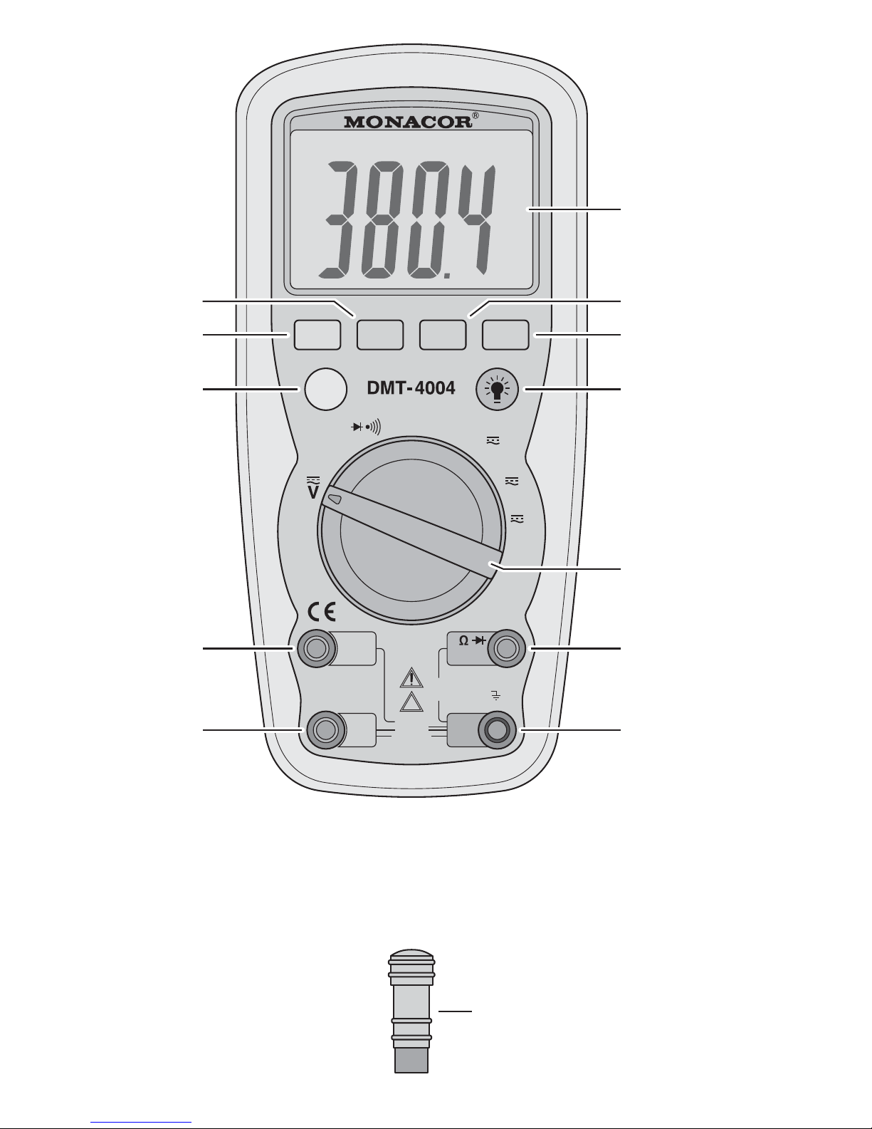
Zum Zurückschalten auf Wechselspan-
nungsmessung die Taste Hz% ein- oder
zweimal drücken, sodass im Display wieder
„AC“ und „V“ angezeigt wird.
5.2 Strommessung
Der zu messende Strom darf 10 A nicht
überschreiten!
Ströme zwischen 1 A und 10 A dürfen nicht
länger als 30 Sekunden gemessen werden.
Anderenfalls können das Instrument und die
Messleitungen beschädigt werden.
1) Für Messungen bis 400 mA die rote Mess-
leitung an die Buchse µA/mA (5) anschlie-
ßen und für Messungen von 400 mA bis
10 A an die Buchse 10A (4). Bei unbekann-
ten Strömen die Messung vorsichtshalber
mit dem 10-A-Bereich beginnen.
Vorsicht! Auf keinen Fall eine Spannungs-
messung vornehmen, wenn die Messleitung
in der Buchse µA/mA oder 10A steckt. Das
Messgerät und die Spannungsquelle kön-
nen beschädigt werden.
2) Den Drehschalter (10) je nach zu messen-
den Strom in die folgende Position stellen:
3) Nach dem Einschalten ist immer die Gleich-
strommessung aktiviert: Das Display (6)
zeigt oben links „DC“ an. Für Wechsel-
strommessungen mit der Taste MODE (3)
auf die Anzeige „AC“ umschalten. Mit der
Taste MODE lässt sich auch wieder auf die
Gleichstrommessung zurückschalten.
4) Das Messgerät über die Messleitungen in
den zu messenden Stromkreis einschleifen
und den Messwert im Display ablesen. Liegt
bei Gleichstrommessungen an der roten
Messspitze der Minuspol und an der schwar-
zen Spitze der Pluspol, erscheint im Display
vor dem Messwert ein Minuszeichen.
Übersteigt in einem Messbereich der
Messstrom den zulässigen Wert, ertönen
Warnsignale und im Display erscheint „OL.“
(overload = Überlast). Der nächsthöhere Be-
reich muss gewählt werden.
5) Während einer Wechselstrommessung
kann mit der Taste Hz% (2) auf die Messung
der Frequenz und des Tastverhältnisses
umgeschaltet werden. Jedoch ist die Ein-
gangsempfindlichkeit nicht so hoch und der
Frequenzbereich nicht so groß wie bei einer
Messung in der Drehschalterposition Hz%:
Zum Zurückschalten auf Wechselstrom-
messung die Taste Hz% ein- oder zweimal
drücken, sodass im Display wieder „AC“
und „A“, „mA“ oder „µA“ angezeigt wird.
5.3 Widerstandsmessung
Einen Widerstand auf keinen Fall bei anlie-
gender Spannung und immer separat mes-
sen, sonst ist die Messung falsch. Dazu
muss er ggf. aus der Schaltung herausgelö-
tet werden.
Den Drehschalter (10) in die Position Ωstellen
und die Messspitzen an den Widerstand hal-
ten. Den Widerstandswert auf dem Display ab-
lesen. Solange sich kein Widerstand zwischen
den Messspitzen befindet oder die Messspit-
zen nicht kurzgeschlossen sind, zeigt das Dis-
play mit „OL.“ einen unendlich hohen Wert an.
5.4 Durchgangssummer
Der Durchgangssummer dient zum Feststellen
von Leitungsunterbrechungen.
Eine Durchgangsprüfung nie bei anliegen-
der Spannung durchführen. Das Instrument
kann beschädigt werden und die Messung
ist falsch.
1) Den Drehschalter (10) in die Position
stellen. Oben im Display erscheint das Sym-
bol für die Diodenprüfung.
2) Mit der Taste MODE (3) auf die Durch-
gangsprüfung umschalten. Oben im Display
erscheint das Summersymbol .
3) Die Prüfspitzen an die entsprechenden
Messpunkte halten. Ist der Widerstand zwi-
schen den Punkte kleiner als 40 Ω, ertönt
der Durchgangssummer. Der Widerstands-
wert wird bis 400 Ω im Display angezeigt.
Bei höheren Werten erscheint die Überlauf-
anzeige „OL.“
Messstrom Position
< 4000 µAµA
4 – 400 mA mA
400 mA – 10 A 10A
Messbereich Empfindlichkeit Frequenzbereich
400 mA~ ≥ 45 mA 5Hz–5kHz
10 A~ ≥ 4 A 5Hz–1kHz
D
A
CH
7

D
A
CH
8
5.5 Diodenprüfung
Eine Diode auf keinen Fall bei anliegender
Spannung und immer separat messen,
sonst ist die Messung falsch. Dazu die Diode
ggf. aus der Schaltung herauslöten.
Den Drehschalter (10) in die Position stel-
len. Oben im Display erscheint das Symbol
für die Diodenprüfung. Beim Anlegen der Prüf-
spitzen an die Diode in Durchlassrichtung wird
die Durchlassspannung bis 0,999 V angezeigt.
Der Pluspol des Messstromes (ca. 0,3 mA)
liegt dabei an der roten Messspitze an.
Bei einer Anzeige von ca. 0 V hat die Diode
einen Kurzschluss. Wird „OL.“ angezeigt, hat
die Diode eine höhere Durchlassspannung als
1 V (z. B. LEDs) oder die Diode hat eine Unter-
brechung, ist in Sperrrichtung angeschlossen
(Diode umpolen) oder berührt nicht die Mess-
spitzen.
5.6 Kapazitätsmessung
Mit dem DMT-4004 können Kondensatoren mit
einer Kapazität bis 200 µF gemessen werden.
Den Drehschalter (10) in die Position CAP stel-
len und den Kondensator an die Messspitzen
halten. Der Messvorgang kann einige Sekun-
den dauern, sodass der richtige Messwert erst
nach einiger Zeit angezeigt wird. Ist die Kapa-
zität größer als 200 µF, erscheint „OL.“ als An-
zeige für das Überschreiten des Messberei-
ches.
5.7 Frequenzmessung
Mit dem Gerät können Frequenzen bis 10 MHz
gemessen werden. Die Empfindlichkeit beträgt:
Den Drehschalter (10) in die Position Hz% dre-
hen. Die Messspitzen an die Messpunkte hal-
ten und die Frequenz vom Display ablesen.
Im Wechselspannungsbereich und in den
Wechselstrombereichen ist ebenfalls eine Fre-
quenzmessung möglich (Kap. 5.1 und 5.2).
5.8 Messung des Tastverhältnisses
Mit dem Instrument lässt sich das Tastverhält-
nis in % messen. Das Tastverhältnis gibt das
Verhältnis des positiven Signalanteils zur Peri-
odendauer an, z. B.:
Messbereich: . . . . . 0,1 % bis 99,9 %
Empfindlichkeit: . . . < 0,5 V~
Frequenzbereich: . . 5 Hz – 150 kHz
Der positive Signalanteil muss 100 µs – 100 ms
lang sein.
1) Den Drehschalter in die Position Hz% stel-
len. Die Frequenzmessung ist eingeschaltet.
2) Mit der Taste Hz% (2) auf Messung des Tast-
verhältnisses umschalten. Rechts im Dis-
play wechselt die Anzeige von „Hz“ auf „%“.
3) Die Messspitzen an die Messpunkte halten
und das Tastverhältnis vom Display ablesen.
4) Zum Zurückschalten auf die Frequenzmes-
sung die Taste Hz% erneut drücken.
Im Wechselspannungsbereich und in den
Wechselstrombereichen ist ebenfalls das Mes-
sen des Tastverhältnisses möglich (Kap. 5.1
und 5.2).
10ms
6,5ms
0
U
t
6,5ms x 100% = 65%
10ms
Frequenz Empfindlichkeit
≤ 1 MHz < 0,5 V~
> 1 MHz > 3 V~
WARNUNG Einen Kondensator nie im gela-
denen Zustand oder bei anlie-
gender Betriebsspannung mes-
sen. Anderenfalls besteht die Ge-
fahr eines elektrischen Schlags.
Außerdem ist die Messung feh-
lerhaft.
Schalten Sie die Stromversorgung aus und
entladen Sie den Kondensator. Dann erst den
Kondensator aus der Schaltung herauslöten.

6 Zusätzliche Funktionen
6.1 Manuelle Bereichswahl
Der Messbereich für eine Messfunktion ist
immer automatisch optimal gewählt, wenn
links oben im Display „AUTO“ erscheint.
1) Zum Festhalten eines automatisch gewähl-
ten Bereiches die Taste RANGE (1) drü-
cken. Die Anzeige „AUTO“ erlischt.
2) Mit jedem weiteren Drücken der Taste
RANGE wird in den nächsthöheren Bereich
geschaltet. Dadurch sinkt die Auflösung des
Messwertes, jedoch wird ein ständiges Um-
schalten verhindert, wenn der Messwert
zwischen zwei Bereichen schwankt.
Ist der höchstmögliche Messbereich er-
reicht, wird mit dem nächsten Tastendruck
auf den kleinsten Bereich geschaltet. Bei
einem zu klein gewählten Bereich wird „OL.“
(overload = überlastet) angezeigt.
3) Zum Zurückschalten auf die automatische
Bereichswahl die Taste RANGE ca. 2 Sek.
gedrückt halten, bis im Display wieder
„AUTO“ erscheint oder mit dem Drehschal-
ter (10) eine andere Messfunktion wählen.
6.2 Messwert festhalten
Ein im Display angezeigter Messwert lässt sich
festhalten, um z. B. nach dem Trennen der
Messspitzen vom Messobjekt den Wert besser
ablesen zu können. Dazu die Taste HOLD (7)
drücken. Oben im Display erscheint „HOLD“.
Zum Zurückschalten auf den aktuellen Mess-
wert die Funktion mit der Taste HOLD wieder
ausschalten („HOLD“ erlischt). Die Funktion ist
auch ausgeschaltet, wenn mit dem Drehschal-
ter (10) eine andere Messfunktion gewählt wird.
6.3 Relativwertmessung
Von einem bestimmten Messwert ausgehend,
können auftretende Abweichungen anzeigt
werden. Die Funktion lässt sich bei Strom-,
Spannungs-, Widerstands- und Kapazitäts-
messungen aktivieren.
1) Eine Messung durchführen. Wird der ge-
wünschte Bezugswert angezeigt, die Taste
REL (8) drücken. Oben im Display erscheint
die Anzeige „REL“.
Die Funktion kann nicht eingeschaltet
werden, wenn das Display „OL.“ anzeigt.
2) Ändert sich der Messwert, wird die Abwei-
chung vom Bezugswert angezeigt.
Die automatische Bereichswahl ist bei
der Relativwertmessung ausgeschaltet. So-
bald der Messbereich überschritten wird,
zeigt das Display „OL.“ an.
3) Zum Ausschalten der Relativwertmessung
die Taste REL erneut betätigen. Bei Bedarf
mit der Taste RANGE die automatische Be-
reichswahl wieder aktivieren (Taste RANGE
ca. 2 Sek. gedrückt halten). Durch Umschal-
ten auf eine andere Messfunktion wird die
Relativwertmessung ebenfalls ausgeschal-
tet.
7 Sicherungen ersetzen
Ist das Messen von Strömen nicht möglich, die
internen Sicherungen überprüfen und durch
Fachpersonal ersetzen lassen.
1) Die sechs Schrauben für die Gehäuse-
schale (zwei befinden sich unter dem Auf-
stellbügel) herausschrauben und die Ge-
häuseschale abnehmen.
2) Defekte Sicherungen nur durch Sicherun-
gen gleichen Typs ersetzen:
µA- und mA-Bereich: F500 mAH/1000 V
10-A-Bereich: F10 AH/1000 V
3) Die Gehäuseschale wieder festschrauben.
Erst danach das Instrument in Betrieb neh-
men.
WARNUNG Vor dem Öffnen des Gehäuses
die Messspitzen von den Mess-
punkten und von den Anschluss-
buchses entfernen. Anderenfalls
besteht die Gefahr eines elektri-
schen Schlages.
D
A
CH
9

8 Technische Daten
Gleich- und Wechselspannung
Messbereiche: . . . . . . . 400 mV, 4 V, 40 V,
400 V, 1000 V
Messgenauigkeit*
400 mV : . . . . . . . . . . ±(0,5 % + 2 Digits)
4 – 400 V : . . . . . . . . ±(1,2 % + 2 Digits)
1000 V : . . . . . . . . . . ±(1,5 % + 2 Digits)
400 mV~: . . . . . . . . . . ±(1,5 % + 70 Digits)
4 V~: . . . . . . . . . . . . . ±(1,2 % + 3 Digits)
40 V~, 400 V~: . . . . . . ±(1,5 % + 3 Digits)
1000 V~: . . . . . . . . . . ±(2,0 % + 4 Digits)
Eingangswiderstand: . . 7,8 MΩ
Überlastschutz: . . . . . . . 1000 V /~
Frequenzbereich bei V~: 50 – 400 Hz
Gleich- und Wechselstrom
Messbereiche: . . . . . . . 400 µA, 4 mA,
40 mA, 400 mA, 10 A
Messgenauigkeit*
400 µA : . . . . . . . . . . ±(1,0 % + 3 Digits)
4 – 400 mA : . . . . . . . ±(1,5 % + 3 Digits)
10 A : . . . . . . . . . . . . ±(2,5 % + 5 Digits)
400 µA~: . . . . . . . . . . ±(1,5 % + 5 Digits)
4 – 400 mA~: . . . . . . . ±(1,8 % + 5 Digits)
10 A~: . . . . . . . . . . . . ±(3,0 % + 7 Digits)
Absicherung
µA- und mA-Bereich: . F500 mAH/1000 V
10-A-Bereich: . . . . . . F10 AH/1000 V
Frequenzbereich bei A~: 50 – 400 Hz
Widerstand
Messbereiche: . . . . . . . 400 Ω, 4 kΩ,
40 kΩ, 400 kΩ,
4 MΩ, 40 MΩ
Messgenauigkeit*
400 Ω: . . . . . . . . . . . . ±(1,2 % + 4 Digits)
4 kΩ: . . . . . . . . . . . . . ± (1,0 % + 2 Digits)
40 kΩ, 400 kΩ, 4 MΩ: ±(1,2 % + 2 Digits)
40 MΩ: . . . . . . . . . . . . ±(2,0 % + 3 Digits)
Überlastschutz: . . . . . . . 600 V /~
Kapazität
Messbereiche: . . . . . . . 4 nF, 40 nF, 400 nF,
4µF, 40 µF, 200 µF
Messgenauigkeit*
4 nF: . . . . . . . . . . . . . ±(5,0 % + 20 Digits)
40 nF: . . . . . . . . . . . . ±(5,0 % + 7 Digits)
400 nF, 4 µF, 40 µF: . . ±(3,0 % + 5 Digits)
200 µF: . . . . . . . . . . . ±(5,0 % + 5 Digits)
Überlastschutz: . . . . . . . 600 V /~
Frequenz
Angaben nur für die Drehschalter-Position Hz%
Messbereiche: . . . . . . . 9,999 Hz, 9,999 kHz
99,99 Hz, 99,99 kHz
999,9 Hz, 999,9 kHz
9,999 MHz
Messgenauigkeit*
9,999 Hz, 99,99 Hz: . . ±(1,5 % + 5 Digits)
999,9 Hz – 999,9 kHz: ±(1,2 % + 3 Digits)
9,999 MHz: . . . . . . . . ±(1,5 % + 4 Digits)
Empfindlichkeit
bei ≤ 1 MHz: . . . . . . . 0,5 V~
bei > 1 MHz: . . . . . . . 3 V~
Überlastschutz: . . . . . . . 600 V /~
Tastverhältnis
Angaben nur für die Drehschalter-Position Hz%
Messbereich: . . . . . . . . 0,1 – 99,9 %
Messgenauigkeit*: . . . . ±(1,2 % + 2 Digits)
Empfindlichkeit: . . . . . . . 0,5 V~
Frequenzbereich: . . . . . 5 Hz – 150 kHz
Überlastschutz: . . . . . . . 600 V /~
Diodenprüfung
Anzeige: . . . . . . . . . . . . Durchlassspannung
bis 0,999 V
Messgenauigkeit*: . . . . ±(10 % + 5 Digits)
Messstrom: . . . . . . . . . . ca. 0,3 mA
max. Messspannung: . . ca. 1,5 V
Überlastschutz: . . . . . . . 600 V /~
D
A
CH
10
* bei 23 °C, ±5 °C, rel. Luftfeuchtigkeit < 70 %

Durchgangssummer
Ansprechschwelle: . . . . < 40 Ω
Messstrom: . . . . . . . . . . ca. 0,3 mA
Überlastschutz: . . . . . . . 600 V /~
Allgemeine Angaben
Display: . . . . . . . . . . . . . 29-mm-LCD,
33/4-stellig
Messrate: . . . . . . . . . . . 2 Messungen
pro Sekunde
Überspannungs-
kategorie: . . . . . . . . . . . CAT III 1000 V und
CAT IV 600 V
Gehäuseschutzklasse: . IP 67
Stromversorgung: . . . . . 9-V-Blockbatterie
Einsatzbereich: . . . . . . . 0 – 50 °C, rel. Luft-
feuchtigkeit < 70 %
Abmessungen: . . . . . . . 83 × 180 × 54 mm
Gewicht: . . . . . . . . . . . . 490 g
Änderungen vorbehalten.
D
A
CH
11
Diese Bedienungsanleitung ist urheberrechtlich für MONACOR
®
INTERNATIONAL GmbH & Co. KG
geschützt. Eine Reproduktion für eigene kommerzielle Zwecke – auch auszugsweise – ist untersagt.

Contents
1 Operating Elements and
Connections . . . . . . . . . . . . . . . . . . . 12
2 Safety Notes . . . . . . . . . . . . . . . . . . . 13
3 Applications . . . . . . . . . . . . . . . . . . . 13
4 Operation . . . . . . . . . . . . . . . . . . . . . . 13
4.1 Inserting or replacing the battery . . . . 13
4.2 Attaching the ATTENTION! label . . . . 14
4.3 Connecting the test leads . . . . . . . . . . 14
5 Measurements . . . . . . . . . . . . . . . . . . 14
5.1 Voltage measurement . . . . . . . . . . . . . 14
5.2 Current measurement . . . . . . . . . . . . . 15
5.3 Resistance measurement . . . . . . . . . . 15
5.4 Continuity buzzer . . . . . . . . . . . . . . . . 15
5.5 Diode test . . . . . . . . . . . . . . . . . . . . . . 16
5.6 Capacitance measurement . . . . . . . . . 16
5.7 Frequency measurement . . . . . . . . . . 16
5.8 Duty cycle measurement . . . . . . . . . . 16
6 Additional Functions . . . . . . . . . . . . 17
6.1 Manual ranging . . . . . . . . . . . . . . . . . . 17
6.2 Data hold . . . . . . . . . . . . . . . . . . . . . . 17
6.3 Relative value measurement . . . . . . . 17
7 Replacing the Fuses . . . . . . . . . . . . . 17
8 Specifications . . . . . . . . . . . . . . . . . . 18
Please unfold page 3. Then you will always
see the operating elements and connec-
tions described.
1 Operating Elements
and Connections
1Button RANGE for manual ranging
2Button Hz% for switching over between fre-
quency measurement and duty cycle meas-
urement
When the selector switch (10) is set to cur-
rent or voltage measurement, the button
Hz% allows to switch to frequency meas-
urement and duty cycle measurement and
also back to current or voltage measure-
ment.
3Button MODE for switching over the test
function (e. g. direct or alternating current
measurement, diode test, or continuity test)
4Jack 10 A for the red test lead for current
measurement 400 mA – 10 A
5Jack µA/mA for the red test lead for current
measurement up to 400 mA max.
6Display
7Button HOLD for freezing a measured
value
8Button REL for relative value measurement
9Button for display illumination:
To activate, keep the button pressed for
2 seconds; to deactivate, shortly actuate
the button.
10 Selector switch for the test functions
11 Jack V Ω CAP Hz% for the red test lead,
for all measurements except current meas-
urements
12 Jack COM for the black test lead
13 Protective sleeve (2 pieces): For outdoor
operation, insert these sleeves into the test
jacks (4, 5, 11) that are not used to ensure
protection of the unit in accordance with
IP 67.
12
GB

2 Safety Notes
This unit corresponds to all required directives
of the EU and is therefore marked with .
Please observe the following items in any
case:
When using the protective sleeves (13), the
unit is protected in accordance with IP 67
and is also suitable for outdoor applications.
However, protect it against extreme high or
low temperatures (admissible ambient tem-
perature range 0 – 50 °C).
For cleaning the housing only use a soft
cloth, slightly wet, if necessary; never use
chemicals or abrasive detergents.
No guarantee claims for the unit and no lia-
bility for any resulting personal damage or
material damage will be accepted if the rele-
vant safety regulations for handling voltages
equal to or higher than 42 V are not ob-
served, if the unit is used for other purposes
than originally intended, if it is not correctly
connected or operated, if it is overloaded or
not repaired in an expert way.
3 Applications
This automatic digital multimeter with a 29 mm
LC display (indication up to 4000) is suited for
measuring:
–voltages up to 1000 V /~
–currents up to 10 A /~
–frequencies up to 10 MHz
–resistances up to 40 MΩ
–capacitances up to 200 µF
Furthermore, it allows to measure the duty
cycle of electric signals and the forward volt-
age of diodes. For continuity tests, a buzzer is
provided.
4 Operation
1) To switch on the multimeter, set the selector
switch (10) from the position OFF to the de-
sired function. If there is no indication on the
display (6), insert a battery (chapter 4.1).
2) If required, unfold the tilt stand on the rear
side to obtain a more convenient reading
position of the display.
3) After operation, set the selector switch to
the position OFF.
The unit will be switched off automatically
if it is not used for 15 minutes. One minute
before it is switched off automatically, there
will be 5 short acoustic signals; when it is
switched off, a longer acoustic signal will
sound. To switch it on again, actuate a but-
ton or the selector switch.
4.1 Inserting or replacing the battery
If there is no indication on the display (6) after
switching on or if the symbol on the left of the
display shows a discharged battery, insert a
9 V battery or replace the battery.
1) Unfold the tilt stand on the rear side and re-
move the two central screws for the battery
compartment cover.
2) Remove the cover and insert a 9 V battery
as indicated in the compartment.
3) Close the battery compartment.
If the meter is not used for a longer period, re-
move the battery to prevent damage due to
battery leakage.
If the unit is to be put out of operation
definitively, take it to a local recycling
plant for a disposal which is not harm-
ful to the environment.
Dead batteries or defective rechargeable bat-
teries do not belong in the household rubbish,
always take them to a special waste disposal
(e. g. collection container at your retailer).
WARNING With this meter, dangerous volt-
ages can be measured. Particu-
lar attention should be paid
when measuring voltages equal
to or higher than 42 V!
1. Wear protective gloves to protect you
against electric shock.
2. When applying the probe tips, make sure
that your fingers are protected behind the
collar of the probe.
3. Never perform measurements when the
meter or the test leads are damaged. Al-
ways replace damaged test leads by origi-
nal test leads.
13
GB

4.2 Attaching the ATTENTION! label
Labels with important infor-
mation in eight languages are
supplied with the meter. At-
tach the corresponding label
in your language to the field
provided on the cover of the
battery compartment!
4.3 Connecting the test leads
The meter is equipped with four test jacks:
1. The jack COM (12) is the common (
-
) jack
for all measurements. Connect the black
test lead to this jack.
2. The jack V Ω CAP Hz% (11) is the com-
mon (+) jack for all measurements, except
for current measurements. Connect the red
test lead to this jack.
3. For current measurements up to 400 mA,
disconnect the red test lead and connect it
to the jack µA/mA (5).
4. For current measurements between 400 mA
and 10 A, disconnect the red test lead and
connect it to the jack 10A (4).
IMPORTANT! For outdoor operation of the
multimeter, insert the protective sleeves sup-
plied (13) into the two test jacks that are not
used. Only this will ensure protection of the unit
in accordance with IP 67.
5 Measurements
Prior to switching over to another test function,
remove the probe tips from the object to be
measured, otherwise the multimeter may be
damaged!
5.1 Voltage measurement
1) Set the selector switch (10) to the position V.
After switching on, the DC voltage measure-
ment will always be activated: The display
(6) will indicate “DC” at the top on the left.
For AC voltage measurements, switch over
to the indication “AC” with the button MODE
(3). The button MODE also allows to return
to the DC voltage measurement.
2) The red test lead must be connected to the
jack V Ω CAP Hz% (11).
Caution! The test lead must not be con-
nected to the jack 10A (4) or µA/mA (5),
otherwise the meter and the object to be
measured may be damaged.
3) Apply the probe tips to the object to be meas-
ured and read the value on the display. If, for
DC voltage measurements, the red probe
tip is applied to the negative pole and the
black tip to the positive pole, a minus sign
will precede the measured value.
4) During an AC voltage measurement, the
button Hz% (2) allows to switch over to fre-
quency measurement and duty cycle meas-
urement, however, the input sensitivity will
not be as high and the frequency range will
not be as large as that for a measurement in
the position Hz% of the selector switch:
To return to AC voltage measurement, press
the button Hz% once or twice so that the dis-
play will indicate “AC” and “V” again.
Measuring range Sensitivity Frequency range
4V~ ≥ 1.5 V~ 5 Hz – 10 kHz
40 V~, 400 V~ ≥ 10 V~ 5 Hz – 20 kHz
≥ 20 V~ 5 Hz – 200 kHz
1000 V~ ≥ 420 V~ 50 Hz – 1 kHz
WARNING Take into account unexpected
voltages on objects to be meas-
ured. Capacitors, for example,
may be dangerously charged
even if the voltage source has
been switched off.
Never perform measurements in electric
circuits with corona discharges (high volt-
age) with this meter. Risk of electrocution!
The maximum voltage to be measured
must not exceed 1000 V¿/~, otherwise you
will risk your life!
WARNING Measurements in circuits carry-
ing more than 42 V must only be
made by persons able to recog-
nize a hazard of contact and to
take the required safety precau-
tions. In case of measurements
with a hazard of contact, avoid
working on your own. Ask a sec-
ond person to assist.
Power supply: 1 x 9
V battery
F10AH/1000V
F500mAH/1000V
ATTENTION!
To prevent the danger of
an electric shock, the probe
tips must be removed from
the connecting jacks and
the measuring spots prior
to opening the housing.
Fuses are inserted to pro-
tect against overvoltage
and fire hazard. Faulty fuses
must only be replaced by
fuses of the same type!
14
GB

5.2 Current measurement
The current to be measured must not ex-
ceed 10 A!
Currents between 1 A and 10 A must not be
measured for more than 30 seconds, other-
wise the meter and the test leads may be
damaged.
1) For measurements up to 400 mA, connect
the red test lead to the jack µA/mA (5); for
measurements between 400 mA and 10 A,
connect it to the jack 10A (4). In case of un-
known currents, start the measurement with
the 10 A range as a precaution.
Caution! Never make a voltage measure-
ment when the test lead is connected to the
jack µA/mA or 10A, otherwise the meter and
the voltage source may be damaged.
2) According to the current to be measured,
set the selector switch (10) to the following
position:
3) After switching on, the direct current meas-
urement will always be activated: The dis-
play (6) will indicate “DC” at the top on the
left. For alternating current measurements,
switch over to the indication “AC” with the
button MODE (3). The button MODE also al-
lows to return to the direct current measure-
ment.
4) Insert the meter via the test leads into the
circuit to be measured and read the meas-
ured value on the display. If, for direct current
measurements, the red probe tip is applied
to the negative pole and the black tip to the
positive pole, a minus sign will precede the
measured value.
If the current measured exceeds the
admissible value of the measuring range,
warning signals will sound and “OL.” (over-
load) will appear on the display. In this case,
select the next higher range.
5) During an alternating current measurement,
the button Hz% (2) allows to switch over to
frequency measurement and duty cycle
measurement, however, the input sensitivity
will not be as high and the frequency range
will not be as large as that for a measure-
ment in the position Hz% of the selector
switch.
To return to alternating current measure-
ment, press the button Hz% once or twice
so that the display will indicate “AC” and “A”,
“mA”, or µA” again.
5.3 Resistance measurement
Never measure a resistor when voltage is
applied, and always measure it separately,
otherwise the measurement will be inaccu-
rate. For this purpose, it may be necessary
to solder it out of the circuit.
Set the selector switch (10) to the position Ω
and apply the probe tips to the resistor. Read
the resistance value on the display. As long as
there is no resistor between the probe tips or
the probe tips are not shorted, the display will
show “OL.” to indicate an infinitely high value.
5.4 Continuity buzzer
The continuity buzzer is used for checking if
current flows without interruption.
Never perform a continuity test when volt-
age is applied, otherwise the meter may be
damaged and the measurement will be
inaccurate.
1) Set the selector switch (10) to the position
. At the top of the display the symbol
for diode test will appear.
2) Switch over to continuity test with the button
MODE (3). At the top of the display the
buzzer symbol will appear.
3) Apply the probe tips to the corresponding
measuring points. If the resistance between
the points is less than 40 Ω, the continuity
buzzer will sound. The resistance value will
be indicated on the display up to 400 Ω; in
case of higher values, the overload indica-
tion “OL.” will appear.
Measuring range Sensitivity Frequency range
400 mA~ ≥ 45 mA 5Hz–5kHz
10 A~ ≥ 4 A 5Hz–1kHz
Current measured Position
< 4000 µAµA
4 – 400 mA mA
400 mA – 10 A 10A
15
GB

5.5 Diode test
Never measure a diode when voltage is ap-
plied, and always measure it separately,
otherwise the measurement will be inaccu-
rate. For this purpose, it may be necessary
to solder the diode out of the circuit.
Set the selector switch (10) to the position .
At the top of the display the symbol for diode
test will appear. When the probe tips are ap-
plied to the diode in forward direction, the for-
ward voltage up to 0.999 V will be indicated.
The positive pole of the measuring current (ap-
prox. 0.3 mA) is applied to the red probe tip.
With an indication of approx. 0 V, the diode
has a short circuit. If “OL.” is indicated, the
diode has a higher forward voltage than 1 V
(e. g. LEDs), the diode is interrupted, con-
nected in reverse direction (reverse the polarity
of the diode), or has no contact to the probe
tips.
5.6 Capacitance measurement
The DMT-4004 allows to measure capacitors
with a capacitance up to 200 µF.
Set the selector switch (10) to the position CAP
and apply the probe tips to the capacitor. The
measuring process may require a few seconds
so that it will take a while until the correct value
is indicated. If the capacitance is higher than
200 µF, “OL.” will appear to indicate that the
measuring range has been exceeded.
5.7 Frequency measurement
This meter allows to measure frequencies up
to 10 MHz. The sensitivity is:
Set the selector switch (10) to the position
Hz%. Apply the probe tips to the measuring
points and read the frequency on the display.
In the AC voltage range and in the alternat-
ing current ranges, a frequency measurement
is also possible (chapters 5.1 and 5.2).
5.8 Duty cycle measurement
The meter allows to measure the duty cycle
in %. The duty cycle is the ratio of the positive
signal part to the period, e. g.:
Measuring range: . . 0.1 % to 99.9 %
Sensitivity: . . . . . . . < 0.5 V~
Frequency range: . 5 Hz – 150 kHz
The positive signal part must be 100 µs–
100 ms.
1) Set the selector switch to the position Hz%.
The frequency measurement is activated.
2) Use the button Hz% (2) to switch over to
duty cycle measurement. On the right of the
display, the indication will change from “Hz”
to “%”.
3) Apply the probe tips to the measuring points
and read the duty cycle on the display.
4) To return to frequency measurement, press
the button Hz% once again.
In the AC voltage range and in the alternating
current ranges, a duty cycle measurement is
also possible (chapters 5.1 and 5.2).
Frequency Sensitivity
≤ 1 MHz < 0.5 V~
> 1 MHz > 3 V~
WARNING Never measure a capacitor
when it is charged or when the
operating voltage is applied, oth-
erwise you will risk an electric
shock. Furthermore, the meas-
urement will be inaccurate.
Switch off the power supply and discharge
the capacitor before soldering it out of the cir-
cuit.
16
GB

6 Additional Functions
6.1 Manual ranging
When “AUTO” appears at the top on the left of
the display, the optimum measuring range for a
test function will always be selected automati-
cally.
1) To hold a range selected automatically,
press the button RANGE (1). The indication
“AUTO” will disappear.
2) Each time the button RANGE is pressed,
the next higher range will be selected. Thus,
the resolution of the measured value will de-
crease, however, this will prevent a continu-
ous switch-over in case the measured value
varies between two ranges.
When the highest possible measuring
range is reached, the smallest range will be
selected when the button is pressed again.
If the range is too small, “OL.” (overload) will
be indicated.
3) To return to autoranging, keep the button
RANGE pressed for approx. 2 seconds until
“AUTO” reappears on the display or select
another test function with the selector switch
(10).
6.2 Data Hold
It is possible to freeze a measured value indi-
cated on the display. This will allow you, for
example, to still read the value even if the
probe tips have already been removed from
the object to be measured. For this purpose,
press the button HOLD (7). At the top of the
display “HOLD” will appear.
To return to the current measured value, de-
activate the function with the button HOLD
(“HOLD” will disappear). The function will also
be deactivated when another test function is
selected with the selector switch (10).
6.3 Relative value measurement
The relative value measurement allows to indi-
cate deviations from a defined measured
value. The function can be activated when
measuring current, voltage, resistance, and
capacitance.
1) Perform a measurement. When the desired
reference value is indicated, press the but-
ton REL (8). At the top of the display, the in-
dication “REL” will appear.
It will not be possible to activate the
function when the display indicates “OL.”.
2) When the measured value changes, the de-
viation from the reference value will be indi-
cated.
For relative value measurement, auto-
ranging will be deactivated. Once the meas-
uring range has been exceeded, the display
will indicate “OL.”.
3) To deactivate the relative value measure-
ment, actuate the button REL once again. If
required, activate autoranging again with
the button RANGE (keep the button RANGE
pressed for approx. 2 seconds). The relative
value measurement will also be deactivated
when another test function is selected.
7 Replacing the Fuses
If it is not possible to measure currents, check
the internal fuses and have them replaced by
skilled personnel.
1) Unscrew the six screws for the housing shell
(two screws are located underneath the tilt
stand) and remove the housing shell.
2) Always replace defective fuses by fuses of
the same type only:
µA and mA range: F500 mAH/1000 V
10 A range: F10 AH/1000 V
3) Screw down the housing shell again before
setting the meter into operation.
WARNING Prior to opening the housing, re-
move the probe tips from the
measuring points and from the
connection jacks, otherwise you
will risk an electric shock.
17
GB

8 Specifications
DC voltage/AC voltage
Measuring ranges: . . . . 400 mV, 4 V, 40 V,
400 V, 1000 V
Measuring accuracy*
400 mV : . . . . . . . . . . ±(0.5 % + 2 digits)
4 – 400 V : . . . . . . . . ±(1.2 % + 2 digits)
1000 V : . . . . . . . . . . ±(1.5 % + 2 digits)
400 mV~: . . . . . . . . . . ±(1.5 % + 70 digits)
4 V~: . . . . . . . . . . . . . ±(1.2 % + 3 digits)
40 V~ , 400 V~: . . . . . ±(1.5 % + 3 digits)
1000 V~: . . . . . . . . . . ±(2.0 % + 4 digits)
Input resistance: . . . . . . 7.8 MΩ
Overload protection: . . . 1000 V /~
Frequency range at V~: 50 – 400 Hz
Direct current/alternating current
Measuring ranges: . . . . 400 µA, 4 mA,
40 mA, 400 mA, 10 A
Measuring accuracy*
400 µA : . . . . . . . . . . ± (1.0 % + 3 digits)
4 – 400 mA : . . . . . . . ±(1.5 % + 3 digits)
10 A : . . . . . . . . . . . . ±(2.5 % + 5 digits)
400 mA~: . . . . . . . . . . ±(1.5 % + 5 digits)
4 – 400 mA ~: . . . . . . . ±(1.8 % + 5 digits)
10 A ~: . . . . . . . . . . . . ±(3.0 % + 7 digits)
Protection
µA and mA range: . . . F500 mAH/1000 V
10 A range: . . . . . . . . F10 AH/1000 V
Frequency range at A~: 50 – 400 Hz
Resistance
Measuring ranges: . . . . 400 Ω, 4 kΩ,
40 kΩ, 400 kΩ,
4 MΩ, 40 MΩ
Measuring accuracy*
400 Ω: . . . . . . . . . . . . ±(1.2 % + 4 digits)
4 kΩ: . . . . . . . . . . . . . ± (1.0 % + 2 digits)
40 kΩ, 400 kΩ, 4 MΩ: ±(1.2 % + 2 digits)
40 MΩ: . . . . . . . . . . . . ±(2.0 % + 3 digits)
Overload protection: . . . 600 V /~
Capacitance
Measuring ranges: . . . . 4 nF, 40 nF, 400 nF,
4µF, 40 µF, 200 µF
Measuring accuracy*
4 nF: . . . . . . . . . . . . . ±(5.0 % + 20 digits)
40 nF: . . . . . . . . . . . . ±(5.0 % + 7 digits)
400 nF, 4 µF, 40 µF: . . ±(3.0 % + 5 digits)
200 µF: . . . . . . . . . . . ±(5.0 % + 5 digits)
Overload protection: . . . 600 V /~
Frequency
Values only for position Hz% of selector switch
Measuring ranges: . . . . 9,999 Hz, 9,999 kHz
99,99 Hz, 99,99 kHz
999,9 Hz, 999,9 kHz
9,999 MHz
Measuring accuracy*
9.999 Hz, 99.99 Hz: . . ±(1.5 % + 5 digits)
999.9 Hz – 999.9 kHz: ±(1.2 % + 3 digits)
9.999 MHz: . . . . . . . . ±(1.5 % + 4 digits)
Sensitivity
at ≤ 1 MHz: . . . . . . . . 0.5 V~
at > 1 MHz: . . . . . . . . 3 V~
Overload protection: . . . 600 V /~
Duty cycle
Values only for position Hz% of selector switch
Measuring range: . . . . . 0.1 – 99.9 %
Measuring accuracy* . . ±(1.2 % + 2 digits)
Sensitivity: . . . . . . . . . . . 0.5 V~
Frequency range: . . . . . 5 Hz – 150 kHz
Overload protection: . . . 600 V /~
Diode test
Indication: . . . . . . . . . . . forward voltage
up to 0.999 V
Measuring accuracy*: . . ±(10 % + 5 digits)
Measuring current: . . . . approx. 0.3 mA
Max. measuring voltage: approx. 1.5 V
Overload protection: . . . 600 V /~
18
GB
* at 23 °C, ±5 % relative humidity < 70 %

Continuity buzzer
Response threshold: . . . < 40 Ω
Measuring current: . . . . approx. 0.3 mA
Overload protection: . . . 600 V /~
General information
Display: . . . . . . . . . . . . . 29 mm LCD,
33/4digits
Measuring rate: . . . . . . . 2 measurements
per second
Overvoltage category: . . CAT III 1000 V and
CAT IV 600 V
Protection class
of housing: . . . . . . . . . . IP 67
Power supply: . . . . . . . . 9 V battery
Operating conditions: . . 0 – 50 °C, relative
humidity < 70 %
Dimensions: . . . . . . . . . 83 × 180 × 54 mm
Weight: . . . . . . . . . . . . . 490 g
Subject to technical modification.
19
GB
All rights reserved by MONACOR
®
INTERNATIONAL GmbH & Co. KG. No part of this instruction
manual may be reproduced in any form or by any means for any commercial use.

Table des matières
1 Eléments et branchements . . . . . . . 20
2 Conseils dʼutilisation et de sécurité 21
3 Possibilités dʼutilisation . . . . . . . . . . 21
4 Fonctionnement . . . . . . . . . . . . . . . . 21
4.1 Insertion ou remplacement
de la batterie . . . . . . . . . . . . . . . . . . . . 21
4.2 Fixer lʼautocollant (ATTENTION !) . . . 22
4.3 Connexion des cordons de mesure . . 22
5 Mesures . . . . . . . . . . . . . . . . . . . . . . . 22
5.1 Mesure de tension . . . . . . . . . . . . . . . 22
5.2 Mesure de courant . . . . . . . . . . . . . . . 23
5.3 Mesure de résistance . . . . . . . . . . . . . 23
5.4 Buzzer de continuité . . . . . . . . . . . . . . 23
5.5 Test de diode . . . . . . . . . . . . . . . . . . . 24
5.6 Mesure de capacité . . . . . . . . . . . . . . 24
5.7 Mesure de fréquence . . . . . . . . . . . . . 24
5.8 Mesure du rapport cyclique . . . . . . . . 24
6 Fonctions supplémentaires . . . . . . . 25
6.1 Sélection manuelle de plage . . . . . . . . 25
6.2 Gel dʼune valeur de mesure . . . . . . . . 25
6.3 Mesure de valeur relative . . . . . . . . . . 25
7 Remplacement des fusibles . . . . . . 25
8 Caractéristiques techniques . . . . . . 26
Ouvrez le présent livret page 3 de manière
à visualiser les éléments et branchements.
1 Eléments et branchements
1Touche RANGE pour une sélection ma-
nuelle de plage
2Touche Hz% pour commuter entre la me-
sure de fréquence et la mesure du rapport
cyclique
Si le sélecteur rotatif (10) est sur mesure de
courant ou de tension, on peut commuter
avec la touche Hz% sur mesure de fré-
quence et mesure du rapport cyclique et re-
venir sur mesure de courant ou de tension.
3Touche MODE pour commuter la fonction
de mesure (par exemple mesure de cou-
rant continu ou alternatif, test de diode ou
test de continuité)
4Prise 10 A pour le cordon de mesure rouge
pour des mesures de courant 400 mA à 10 A
5Prise µA/mA pour le cordon de mesure
rouge pour des mesures de courant
jusquʼà 400 mA max.
6Affichage
7Touche HOLD pour geler une valeur de
mesure
8Touche REL pour la mesure de valeurs re-
latives
9Touche pour lʼéclairage de lʼaffichage :
maintenez la touche enfoncée 2 secondes
pour lʼactiver ; pour le désactiver, appuyez
brièvement sur la touche.
10 Sélecteur rotatif pour sélectionner la fonc-
tion de mesure
11 Prise V Ω CAP Hz% pour le cordon de
mesure rouge pour toutes les mesures
sauf mesures de courant
12 Prise COM pour le cordon de mesure noir
13 Embout (2 pièces) : pour une utilisation en
extérieur, il faut placer les deux embouts
dans les deux prises de mesure inutilisées
(4, 5, 11) pour que lʼappareil soit protégé
selon la classe de protection IP 67.
20
F
B
CH
Table of contents
Languages:
Other Monacor Multimeter manuals

Monacor
Monacor DMT-3090RS User manual

Monacor
Monacor DMT-1020 User manual

Monacor
Monacor DMT-2050 User manual

Monacor
Monacor DMT-4010RMS User manual

Monacor
Monacor DMT-3060 User manual

Monacor
Monacor DMT-1005 User manual

Monacor
Monacor DMT-1050 User manual

Monacor
Monacor DMT-3050 User manual

Monacor
Monacor DMT-2004 User manual

Monacor
Monacor MT-300 User manual