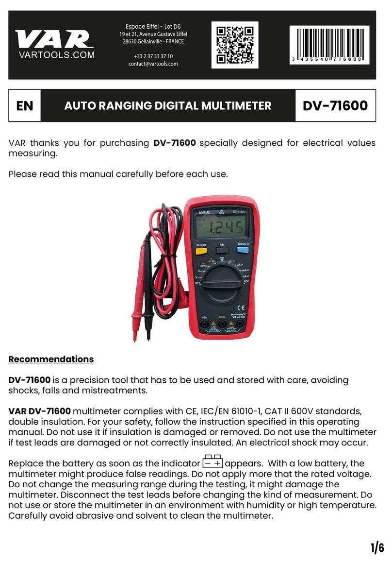
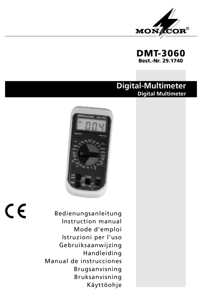
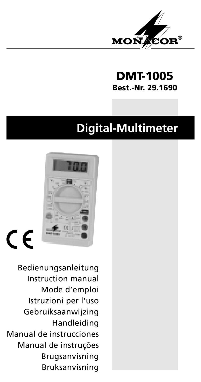
Monacor DMT-1050 User manual

DIGITAL-MULTIMETER ®
DMT-1050
Best.-Nr. 29.1860
BEDIENUNGSANLEITUNG
INSTRUCTION MANUAL
MODE D’EMPLOI
ISTRUZIONI PER L’USO
INSTRUKCJA OBSŁUGI
VEILIGHEIDSVOORSCHRIFTEN
CONSEJOS DE SEGURIDAD
SIKKERHEDSOPLYSNINGER
SÄKERHETSFÖRESKRIFTER
TURVALLISUUDESTA

2
Bevor Sie einschalten
Wir wünschen Ihnen viel Spaß
mit Ihrem neuen Gerät von
MONACOR. Bitte lesen Sie
vor dem Gebrauch diese An-
leitung. Der deutsche Text be-
ginnt auf der Seite 4.
D
A
CH
Before you switch on
We wish you much pleasure
with your new unit by
MONACOR. Please read
these instructions before use.
The English text starts on
page 12.
GB
Avant toute utilisation
Nous vous remercions d'avoir
choisi un appareil MONACOR
et vous prions de lire cette
notice.
La version française com-
mence à la page 20.
F
B
CH
Prima di accendere
Vi auguriamo buon diverti-
mento con il Vostro nuovo ap-
parecchio MONACOR. Vi pre-
ghiamo di leggere le presenti
istruzioni prima dell'uso. Il testo
italiano inizia a pagina 28.
I
Antes de la conexión
Le agradecemos el haber ad-
quirido un equipo MONACOR.
Por favor, lee atentamente las
instrucciones de seguridad
antes del uso. Las instrucio-
nes de seguridad se encuen-
tran en la página 45.
B
PL Alvorens u inschakelt
Wij raden u aan deze hand-
leiding goed door te lezen
voor u het apparaat in gebruik
neemt.
U vindt de veiligheidsvoor-
schriften op pagina 44.
NL
Inden De tænder for
apparatet
Vi ønsker Dem god fornøjelse
med Deres nye apparat. Læs
hele brugsanvisningen igen-
nemførbrug.Sikkerhedsoplys-
ningerne finder De på side 46.
DK
Innan enheten tas i bruk
Läs igenom bruksanvisningen
för att undvika fel och/eller
skador på densamma.
Du finner säkerhetsinstruktio-
nerna på sidan 47.
S
Ennen virran kytkemistä
Toivomme että saat paljon
hyötyä ja iloa uudesta
MONACOR-laitteestasi. Lue
nämä ohjeet ennen käyttöä.
Käyttöohjeet löydät sivulta 48.
FIN
Przed Uruchomieniem
Życzymy Państwu zadowole-
nia z nowego urządzenia firmy
MONACOR. Prosimy o zapoz-
nanie się z niniejsza instrukcją
przed przystąpieniem do jego
użytkowania. Tekst polski za-
czyna się na stronie 36.
E
3
DMT-1050
®
10ADC COM VΩmA
10A MAX
unfused
MAX 600V—
200mA MAX
CAT II 600V
HOLD
ECBE
NPN
PNP
IEC
1010
OFF 600600
200200
B
B
20
2
200m
V¿
V~
A¿
200 µ
2m
20m
200m
2M
200k
Ω
20k
2k 200
10A
hFE
1
2
3
4
5
6
7

Bitte klappen Sie die Seite 3 heraus. Sie sehen dann immer die
beschriebenen Bedienelemente und Anschlüsse.
Inhalt
1Übersicht der Bedienelemente und Anschlüsse . . . . . . . . . . . . . 4
2Hinweise für den sicheren Gebrauch . . . . . . . . . . . . . . . . . . . . . 5
3Verwendungsmöglichkeiten . . . . . . . . . . . . . . . . . . . . . . . . . . . . 5
4 Inbetriebnahme . . . . . . . . . . . . . . . . . . . . . . . . . . . . . . . . . . . . . . 6
5Messungen durchführen . . . . . . . . . . . . . . . . . . . . . . . . . . . . . . . 6
5.1 Spannungsmessung . . . . . . . . . . . . . . . . . . . . . . . . . . . . . . . . . . 6
5.2 Gleichstrommessung . . . . . . . . . . . . . . . . . . . . . . . . . . . . . . . . . 7
5.3 Widerstandsmessung . . . . . . . . . . . . . . . . . . . . . . . . . . . . . . . . . 8
5.4 Durchgangsprüfung . . . . . . . . . . . . . . . . . . . . . . . . . . . . . . . . . . 8
5.5 Stromverstärkung von Transistoren . . . . . . . . . . . . . . . . . . . . . . 8
5.6 Diodentest . . . . . . . . . . . . . . . . . . . . . . . . . . . . . . . . . . . . . . . . . 9
5.7 Messwert festhalten . . . . . . . . . . . . . . . . . . . . . . . . . . . . . . . . . . 9
6Batterie oder Sicherung auswechseln . . . . . . . . . . . . . . . . . . . . 9
7Technische Daten . . . . . . . . . . . . . . . . . . . . . . . . . . . . . . . . . . . 10
1Übersicht der Bedienelemente und Anschlüsse
1LCD-Display
2Taste „HOLD“ zum Festhalten eines Messwertes
3Anschlussbuchse „COM“ für die schwarze Messleitung (Minuspol)
4Anschlussbuchse „10ADC“ für die rote Messleitung (Pluspol) bei
Messungen von Gleichströmen zwischen 200 mA und max. 10 A
5Drehschalter zum Einstellen des Messbereichs
6Steckanschlüsse zur Messung der Stromverstärkung bei Transis-
toren
7Anschlussbuchse „VΩmA“ für die rote Messleitung (Pluspol) bei
Messungen von Spannungen, Strömen unter 200 mA, Widerstän-
den und Dioden
D
A
CH
4

2Hinweise für den sicheren Gebrauch
Dieses Gerät entspricht der Richtlinie für elektromagnetische Verträg-
lichkeit 89/336/EWG und der Niederspannungsrichtlinie 73/23/EWG.
Beachten Sie auch unbedingt die folgenden Punkte:
●Das Gerät ist nur zur Verwendung im Innenbereich geeignet. Schüt-
zen Sie es vor Tropf- und Spritzwasser, hoher Luftfeuchtigkeit und
Hitze (zulässiger Einsatztemperaturbereich 0 – 40 °C).
●Verwenden Sie für die Reinigung nur ein trockenes, weiches Tuch,
auf keinen Fall Chemikalien oder Wasser.
●Werden die geltenden Sicherheitsvorschriften beim Umgang mit
Spannungen ab 42 V nicht eingehalten oder wird das Gerät zweck-
entfremdet, falsch bedient bzw. falsch angeschlossen, überlastet
oder nicht fachgerecht repariert, kann keine Haftung für daraus
resultierende Sach- oder Personenschäden und keine Garantie für
das Gerät übernommen werden.
●Soll das Gerät endgültig aus dem Betrieb genommen werden, über-
geben Sie es zur umweltgerechten Entsorgung einem örtlichen
Recyclingbetrieb.
3Verwendungsmöglichkeiten
Das Digital-Multimeter DMT-1050 dient zur Messung von Gleich- und
Wechselspannungen, Gleichströmen und Widerständen. Außerdem
können Dioden getestet und bei Transistoren die Stromverstärkung
(hFE) gemessen werden. Zur Durchgangsprüfung ist ein Summer vor-
handen.
Vorsicht!
Mit diesem Gerät können lebensgefährlich hohe Spannungen gemes-
sen werden. Bei Messungen von Spannungen ab 42 V ist besondere
Sorgfalt geboten! Achten Sie beim Anlegen der Messspitzen darauf,
dass Ihre Finger sich hinter dem Abrutschschutz befinden. Betreiben
Sie das Multimeter nicht, wenn Sie Schäden am Gerät oder an den
Messleitungen feststellen. Beschädigte Messleitungen müssen aus-
getauscht werden.
D
A
CH
5

4Inbetriebnahme
1) Für eine günstige Ableseposition den Aufstellbügel auf der Rück-
seite des Gummi-Schutzrahmens herausklappen.
2) Den Drehschalter (5) auf den gewünschten Messbereich stellen.
3) Im Display (1) erscheint eine Anzeige. Bleibt das Display dunkel,
muss eine 9-V-Batterie eingesetzt werden. Erscheint im Display das
Symbol , muss die Batterie ausgewechselt werden. Zum Einset-
zen einer neuen Batterie siehe Kapitel 6 „Batterie oder Sicherung
auswechseln“.
4) Nach dem Betrieb das Gerät immer ausschalten (Drehschalter auf
Position „OFF“), sonst wird die Batterie unnötig verbraucht.
Wird das Multimeter längere Zeit nicht gebraucht, sollte die Bat-
terie herausgenommen werden. So werden bei einem Auslaufen
der Batterie mögliche Schäden am Gerät vermieden.
5Messungen durchführen
Messungen in Stromkreisen, an denen über 42 V anliegen, dürfen
nur von Personen durchgeführt werden, die Berührungsgefahren
erkennen und entsprechende Sicherheitsvorkehrungen treffen
können. Bei Messungen mit Berührungsgefahr vermeiden Sie es,
allein zu arbeiten. Bitten Sie eine zweite Person dazu.
Bei unbekannten Spannungs- oder Stromwerten zunächst den größten
Messbereich wählen (600 V bzw. 10 A), um das Messgerät nicht zu über-
lasten. Anschließend für eine hohe Genauigkeit den kleinstmöglichen
Messbereich wählen (z. B. 15 V im 20-V-Bereich messen und nicht im
200-V-Bereich). Ist ein Messbereich überschritten, signalisiert das
Gerät „1“ oder „
-
1“. In diesem Fall den nächstgrößeren Bereich wählen.
5.1 Spannungsmessung
●Rechnen Sie mit unvorhergesehenen Spannungen an Messobjek-
ten. Zum Beispiel können Kondensatoren auch bei ausgeschalteter
Spannungsquelle gefährlich geladen sein.
●Mit diesem Instrument dürfen Sie keine Messungen in Stromkreisen
mit Korona-Entladungen (Hochspannung) durchführen. Lebensge-
fahr!
●Die maximal zu messende Spannung darf 600 V /~ nicht über-
schreiten. Andernfalls besteht Lebensgefahr!
B
D
A
CH
6

1) Die schwarze Messleitung an die Buchse „COM“ (3) anschließen
und die rote Messleitung an die Buchse „VΩmA“ (7). Auf keinen Fall
versehentlich die Buchse „10ADC“ (4) verwenden! Das Messgerät
und das Messobjekt können beschädigt werden.
2) Bei Wechselspannungen den Drehschalter (5) in einen der beiden
Bereiche „V~“ stellen, bei Gleichspannungen in einen der fünf
Bereiche „V “.
3) Die Messspitzen an das Messobjekt halten und auf dem Display
den Wert ablesen.
4) Liegt bei Gleichspannungsmessungen an der roten Messspitze der
Minuspol und an der schwarzen Spitze der Pluspol, erscheint im
Display vor dem Messwert ein Minuszeichen.
5.2 Gleichstrommessung
●Der maximal zu messende Gleichstrom darf 10 A nicht überschrei-
ten.
●Der 10-A-Messkreis ist nicht abgesichert. Hier ist besondere Vor-
sicht geboten.
●Ist die rote Messleitung an der Buchse „10ADC“ (4) angeschlossen,
auf keinen Fall versehentlich eine Spannung messen. Das Mess-
gerät und das Messobjekt können beschädigt werden.
1) Die schwarze Messleitung an die Buchse „COM“ (3) anschließen.
Bei Strömen zwischen 200 mA und max. 10 A die rote Messleitung
in die Buchse „10ADC“ (4) stecken und den Bereichsschalter (5) in
die Position „10A“ drehen.
Bei Strömen bis 200 mA die rote Messleitung in die Buchse
„VΩmA“ (7) stecken und den Bereichsschalter (5) zunächst in die
Position „200m“ des Gleichstrombereichs „A “ drehen. Nach der
Messung ggf. einen kleineren Bereich wählen.
2) Den zu messenden Stromkreis auftrennen und das Messgerät in
Stromkreis schalten.
3) Liegt bei Gleichstrommessungen an der roten Messspitze der
Minuspol und an der schwarzen Spitze der Pluspol, erscheint im
Display vor dem Messwert ein Minuszeichen.
D
A
CH
7

5.3 Widerstandsmessung
●Das Gerät ist bis 250 V /~ überlastgeschützt. Trotzdem nicht inner-
halb einer Schaltung messen, wenn diese unter Spannung steht.
●Einen Widerstand immer separat messen, sonst ist die Messung
falsch. Dazu muss er ggf. aus der Schaltung herausgelötet werden.
1) Die schwarze Messleitung an die Buchse „COM“ (3) anschließen
und die rote Messleitung an die Buchse „VΩmA“ (7).
2) Den Drehschalter (5) in einen der Bereiche „Ω“ stellen.
3) Die Messspitzen an den Widerstand bzw. an die entsprechenden
Messpunkte halten.
5.4 Durchgangsprüfung
●Das Gerät ist bis 250 V /~ überlastgeschützt. Trotzdem nicht inner-
halb einer Schaltung messen, wenn diese unter Spannung steht.
1) Die schwarze Messleitung an die Buchse „COM“ (3) anschließen
und die rote Messleitung an die Buchse „VΩmA“ (7).
2) Den Bereichsschalter (5) in die Position stellen.
3) Die Messspitzen an die entsprechenden Messpunkte halten. Der
Summer ertönt, wenn der Durchgangswiderstand kleiner als 1,5 kΩ
ist.
5.5 Stromverstärkung von Transistoren
●Um einen elektrischen Schlag zu vermeiden, unbedingt die Mess-
spitzen von den vorherigen Messpunkten entfernen, bevor ein Tran-
sistor in die Steckanschlüsse (6) eingesetzt wird.
1) Den Transistor seinen Anschlüssen entsprechend (E, B, C) in die
Steckanschlüsse (6) einsetzen. Für NPN-Typen die obere Sockel-
hälfte verwenden und für PNP-Typen die untere Sockelhälfte.
2) Den Drehschalter (5) in die Position „hFE“ stellen.
3) Das Display zeigt die Stromverstärkung (max. 1000) bei einem
Basisstrom (IB) von 10 µA und einer Kollektor-Emitter-Spannung
(UCE) von 3 V an.
4) Bevor eine Spannungsmessung vorgenommen wird, den Transistor
aus den Steckanschlüssen herausziehen.
D
A
CH
8

5.6 Diodentest
1) Die schwarze Messleitung an die Buchse „COM“ (3) anschließen
und die rote Messleitung an die Buchse „VΩmA“ (7).
2) Den Drehschalter (5) in die Position stellen.
3) Die Kathode der Diode an die schwarze Messspitze halten und die
Anode an die rote Spitze.
4) Das Display zeigt die ungefähre Durchlassspannung in mV bei
einem Teststrom von ca. 0,5 mA an.
Bei einer Anzeige von 0 V hat die Diode den Kurzschluss.
Bei der Anzeige „1“ ist die Diode unterbrochen oder in Sperrrichtung
angeschlossen (Diode umpolen).
5.7 Messwert festhalten
Um eine Messwertanzeige festzuhalten, die Taste „HOLD“ (2) ein-
rasten. Im Display erscheint das Symbol . Zum Zurückschalten auf
den aktuellen Messwert die Taste wieder lösen.
6Batterie oder Sicherung auswechseln
●Vor dem Öffnen des Gerätes unbedingt die Messspitzen von den
Messpunkten der Schaltung entfernen, um einen eventuellen elektri-
schen Schlag zu vermeiden.
●Betreiben Sie das Messgerät niemals im geöffneten Zustand.
●Werfen Sie verbrauchte Batterien nicht in den Hausmüll, sondern ge-
ben Sie sie nur in den Sondermüll (z. B. Sammelbehälter bei Ihrem
Einzelhändler).
aErscheint im Display das Symbol , ist die Batterie verbraucht und
muss durch eine neue 9-V-Blockbatterie ersetzt werden.
bWenn keine Strommessung in den Bereichen bis 200 mA möglich ist,
die interne Sicherung (F200 mA/250 V) überprüfen und ggf. ersetzen.
Zum Öffnen des Gerätes den Gummi-Schutzrahmen entfernen. Die
zwei Schrauben auf der Geräterückseite abschrauben und die untere
Gehäuseschale abnehmen.
Nach dem Austausch der Batterie bzw. der Sicherung die beiden
Gehäuseschalen zusammensetzen und fest verschrauben. Erst dann
das Instrument wieder in Betrieb nehmen. Bei Bedarf den Schutzrah-
men wieder aufsetzen.
H
D
A
CH
9

7Technische Daten
Gleichspannung
Messbereiche: . . . . . . . . . . 200 mV, 2 V, 20 V, 200 V, 600 V
Messgenauigkeit*
200 mV – 200 V: . . . . . . ±(0,5 % + 2 Digits)
600 V: . . . . . . . . . . . . . . ±(0,8 % + 2 Digits)
Eingangswiderstand: . . . . . 1 MΩ
Überlastschutz
200 mV: . . . . . . . . . . . . . 250 V /~
2V–600V: .. . . . . . . . . 600 V /~
Wechselspannung
Messbereiche: . . . . . . . . . . 200 V, 600 V
Frequenzbereich: . . . . . . . 40 – 400 Hz
Messgenauigkeit*: . . . . . . . ±(1,2 % + 10 Digits)
Eingangswiderstand: . . . . . 1 MΩ
Überlastschutz: . . . . . . . . . 600 V /~
Gleichstrom
Messbereiche: . . . . . . . . . . 200 µA, 2 mA, 20 mA, 200 mA, 10 A
Messgenauigkeit*
200 µA – 20 mA: . . . . . . ±(1 % + 2 Digits)
200 mA: . . . . . . . . . . . . . ±(1,5 % + 2 Digits)
10 A: . . . . . . . . . . . . . . . ±(3 % + 2 Digits)
Überlastschutz
200 µA – 200 mA: . . . . . Schmelzsicherung F200 mA/250 V
10 A: . . . . . . . . . . . . . . . ungesichert
Widerstand
Messbereiche: . . . . . . . . . . 200 Ω, 2 kΩ, 20 kΩ, 200 kΩ, 2 MΩ
Messgenauigkeit*
200 Ω: . . . . . . . . . . . . . . ±(0,8 % + 3 Digits)
2kΩ–200 kΩ: . . . . . . . . ±(0,8 % + 2 Digits)
2MΩ: . . . . . . . . . . . . . . ±(1 % + 2 Digits)
max. Messspannung: . . . . 3,2 V
Überlastschutz: . . . . . . . . . 250 V /~
D
A
CH
10

Durchgangssummer
Ansprechschwelle: . . . . . . < 1,5 kΩ
Überlastschutz: . . . . . . . . . 250 V /~
Diodentest
Anzeige: . . . . . . . . . . . . . . ungefähre Durchlassspannung bis 2 V
Messstrom: . . . . . . . . . . . . ca. 0,5 mA
Überlastschutz: . . . . . . . . . 250 V /~
Transistortest hFE
Messbereich: . . . . . . . . . . . 0 – 1000
Teststrom: . . . . . . . . . . . . . IB= 10 µA
Testspannung: . . . . . . . . . . UCE = 3 V
Allgemeine Angaben
Display: . . . . . . . . . . . . . . . 15-mm-LCD, 31/2stellig
Messrate: . . . . . . . . . . . . . 2 – 3 Messungen pro Sek.
Stromversorgung: . . . . . . . 1 x 9-V-Batterie
(nicht im Lieferumfang)
Einsatzbereich: . . . . . . . . . 0 – 40 °C, rel. Luftfeuchtigkeit < 80 %
Abmessungen: . . . . . . . . . 75 x 150 x 40 mm
Gewicht: . . . . . . . . . . . . . . 250 g
*bei 23 °C, ±5 °C
Laut Angaben des Herstellers.
Änderungen vorbehalten.
D
A
CH
11
Diese Bedienungsanleitung ist urheberrechtlich für MONACOR ®INTER-
NATIONAL GmbH & Co. KG geschützt. Eine Reproduktion für eigene
kommerzielle Zwecke – auch auszugsweise – ist untersagt.

Please unfold page 3. Then you can always see the operating ele-
ments and connections described.
Contents
1Operating Elements and Connections . . . . . . . . . . . . . . . . . . . 12
2 Safety Notes . . . . . . . . . . . . . . . . . . . . . . . . . . . . . . . . . . . . . . . 13
3 Applications . . . . . . . . . . . . . . . . . . . . . . . . . . . . . . . . . . . . . . . 13
4Setting the Meter into Operation . . . . . . . . . . . . . . . . . . . . . . . . 14
5 Measurements . . . . . . . . . . . . . . . . . . . . . . . . . . . . . . . . . . . . . 14
5.1 Voltage measurement . . . . . . . . . . . . . . . . . . . . . . . . . . . . . . . . 14
5.2 DC current measurement . . . . . . . . . . . . . . . . . . . . . . . . . . . . . 15
5.3 Resistance measurement . . . . . . . . . . . . . . . . . . . . . . . . . . . . . 16
5.4 Continuity test . . . . . . . . . . . . . . . . . . . . . . . . . . . . . . . . . . . . . . 16
5.5 Current amplification of transistors . . . . . . . . . . . . . . . . . . . . . . 16
5.6 Diode test . . . . . . . . . . . . . . . . . . . . . . . . . . . . . . . . . . . . . . . . . 17
5.7 Holding a measured value . . . . . . . . . . . . . . . . . . . . . . . . . . . . 17
6 Replacing the Battery or Fuse . . . . . . . . . . . . . . . . . . . . . . . . . 17
7 Specifications . . . . . . . . . . . . . . . . . . . . . . . . . . . . . . . . . . . . . . 18
1Operating Elements and Connections
1LCD display
2Button “HOLD” for holding a measured value
3Jack “COM” for connecting the black test lead (negative pole)
4Jack “10ADC” for connecting the red test lead (positive pole) when
measuring DC currents between 200 mA and 10 A max.
5Selector switch for adjusting the measuring range
6Socket for measuring the current amplification of transistors
7Jack “VΩmA” for connecting the red test lead (positive pole) when
measuring voltages, currents below 200 mA, resistances, and
diodes
GB
12

2Safety Notes
This unit corresponds to the directive for electromagnetic compatibility
89/336/EEC and to the low voltage directive 73/23/EEC.
Please observe the following items in any case:
●The unit is suitable for indoor use only. Protect it against dripping
water and splash water, high air humidity, and heat (admissible
ambient temperature range 0 – 40 °C).
●For cleaning only use a dry, soft cloth; never use chemicals or water.
●No guarantee claims for the unit and no liability for any resulting per-
sonal damage or material damage will be accepted if the prevailing
safety precautions for handling voltages equal to or greater than 42 V
are not observed, if the meter is used for other purposes than orig-
inally intended, if it is not correctly operated or connected, if it is over-
loaded, or not repaired in an expert way.
●If the meter is to be put out of operation definitively, take it to a local
recycling plant for a disposal which is not harmful to the environment.
3Applications
The digital multimeter DMT-1050 is suitable for measuring DC and AC
voltages, DC currents, and resistances. Furthermore, it is possible to
test diodes and to measure the current amplification (hFE) of transis-
tors. For continuity tests, a buzzer is provided.
Caution!
With this meter, very high voltages dangerous to life can be meas-
ured. Particular care must be taken when measuring voltages equal to
or greater than 42 V! When handling the measuring tips, always make
sure to keep your fingers behind the protection. Never operate the
multimeter if the unit or the test leads are damaged. Damaged test
leads must be replaced.
GB
13

4Setting the Meter into Operation
1) To obtain a good reading position, unfold the tilt stand on the rear
side of the protective rubber frame.
2) Set the selector switch (5) to the desired measuring range.
3) A display (1) will appear. If it fails to appear, insert a 9 V battery. If
the symbol is displayed, replace the battery – see chapter 6
“Replacing the Battery or Fuse”.
4) Always switch off the meter after operation (selector switch set to
“OFF”), otherwise there will be unnecessary battery consumption.
If the multimeter is not used for a longer period, the battery
should be removed to prevent damage to the meter in case of bat-
tery leakage.
5Measurements
Measurements in circuits carrying more than 42 V must only be
made by persons able to recognize a hazard of contact and to
take the required safety precautions. In case of measurements
with a hazard of contact, avoid working on your own. Ask a
second person to assist.
In case of unknown voltage or current values, always start with the
highest measuring range (600 V or 10 A) to prevent overload of the
meter. For a high accuracy, then select the smallest possible meas-
uring range (e. g. for 15 V, use the 20 V range instead of the 200 V
range). If a measuring range is exceeded, the meter will indicate “1” or
“
-
1”. In this case, select the next higher range.
5.1 Voltage measurement
●Take into account unexpected voltages at test objects. Capacitors,
for example, may be dangerously charged even if the voltage
source has been switched off.
●With this meter, no measurements in current circuits with corona
discharges (high voltage) must be carried out. Danger to life!
●The maximum voltage to be measured must not exceed 600 V /~.
Otherwise you will risk your life!
B
GB
14

1) Connect the black test lead to the jack “COM” (3) and the red test
lead to the jack “VΩmA” (7). Do not accidentally use the jack
“10ADC” (4), otherwise the meter and the test object may be
damaged.
2) For AC voltages, set the selector switch (5) to one of the two ranges
“V~”, for DC voltage to one of the five ranges “V ”.
3) Hold the test tips to the test object and read the measured value on
the display.
4) In case of DC voltage measurements, a minus sign will precede the
measured value if the negative pole is at the red test tip and the
positive pole is at the black test tip.
5.2 DC current measurement
●The maximum DC current to be measured must not exceed 10 A.
●The 10 A measuring circuit is not fused. Special care must be taken.
●With the red test lead connected to the jack “10ADC” (4), do not
accidentally measure a voltage, otherwise the meter and the test
object may be damaged.
1) Connect the black test lead to the jack “COM” (3). In case of current
values between 200 mA and 10 A max., connect the red test lead to
the jack “10ADC” (4) and set the selector switch (5) to the position
“10A”.
With current values up to 200 mA, connect the red test lead to the
jack “VΩmA” (7). For the time being, set the selector switch (5) to
the position “200m” of the DC current range “A ”. After the meas-
urement, select a smaller range, if required.
2) Open the circuit to be measured and connect the meter.
3) In case of DC current measurements, a minus sign will precede the
measured value if the negative pole is at the red test tip and the
positive pole is at the black test tip.
GB
15

5.3 Resistance measurement
●The meter is overload-protected up to 250 V /~. However, never
make measurements within a live circuit.
●Always measure a resistor separately, otherwise the measurement
will be inaccurate. For this purpose, it must be soldered out of the
circuit, if required.
1) Connect the black test lead to the jack “COM” (3) and the red test
lead to the jack “VΩmA” (7).
2) Set the selector switch (5) to one of the “Ω” ranges.
3) Hold the test tips to the resistor or the corresponding measuring
points.
5.4 Continuity test
●The meter is overload-protected up to 250 V /~. However, never
make measurements within a live circuit.
1) Connect the black test lead to the jack “COM” (3) and the red test
lead to the jack “VΩmA” (7).
2) Set the selector switch (5) to the position .
3) Hold the test tips to the corresponding measuring points. The buz-
zer will sound if the resistance is less than 1.5 kΩ.
5.5 Current amplification of transistors
●To prevent an electric shock, always remove the test tips from the
previous measuring points before inserting a transistor into the
socket (6).
1) Insert the transistor into the socket (6) according to its terminals
(E, B, C). For NPN types, use the upper half of the socket, for PNP
types the lower half.
2) Set the selector switch (5) to the position “hFE”.
3) The display shows the current amplification (max. 1000) in case of
a basic current (IB) of 10 µA and a collector-emitter voltage (UCE) of
3V.
4) Prior to making a voltage measurement, remove the transistor from
the socket.
GB
16

5.6 Diode test
1) Connect the black test lead to the jack “COM” (3) and the red test
lead to the jack “VΩmA” (7).
2) Set the selector switch (5) to the position .
3) Hold the cathode of the diode to the black test tip and the anode to
the red tip.
4) The display will show the approximate forward voltage in mV at a
test current of approx. 0.5 mA.
With 0 V displayed, the diode has a short circuit.
With “1” displayed, the diode is interrupted or connected in reverse
direction (change the polarity of the diode).
5.7 Holding a measured value
For holding a measured value, lock the button “HOLD” (2). The symbol
will be displayed. To return to the present measuring value, unlock
the button again.
6Replacing the Battery or Fuse
●Prior to opening the meter, always remove the test tips from the
measuring points of the circuit to prevent any hazard of an electric
shock.
●Never operate the meter when it is open.
●Exhausted batteries do not belong in the household rubbish. Always
take them to a special waste disposal (e. g. collecting container at
your retailer).
aIf the symbol is displayed, the battery is exhausted and must be
replaced by a new 9 V battery.
bIf no current measurement is possible in the ranges up to 200 mA,
check the internal fuse (F200 mA/250 V) and replace it, if required.
To open the meter, remove the protective rubber frame. Unscrew the
two screws on the rear side of the meter and remove the lower shell.
After replacing the battery or fuse, reassemble the two shells and
fasten the screws. The meter must be reassembled before it is oper-
ated again. Replace the protective frame, if required.
H
GB
17

7Specifications
DC voltage
Measuring ranges: . . . . . . 200 mV, 2 V, 20 V, 200 V, 600 V
Measuring accuracy*
200 mV – 200 V: . . . . . . ±(0.5 % + 2 digits)
600 V: . . . . . . . . . . . . . . ±(0.8 % + 2 digits)
Input resistance . . . . . . . . . 1 MΩ
Overload protection
200 mV: . . . . . . . . . . . . . 250 V /~
2V–600V: .. . . . . . . . . 600 V /~
AC voltage
Measuring ranges: . . . . . . 200 V, 600 V
Frequency range: . . . . . . . 40 – 400 Hz
Measuring accuracy*: . . . . ±(1.2 % + 10 digits)
Input resistance: . . . . . . . . 1 MΩ
Overload protection: . . . . . 600 V /~
DC current
Measuring ranges: . . . . . . 200 µA, 2 mA, 20 mA, 200 mA, 10 A
Measuring accuracy*
200 µA – 20 mA: . . . . . . ±(1 % + 2 digits)
200 mA: . . . . . . . . . . . . . ±(1.5 % + 2 digits)
10 A: . . . . . . . . . . . . . . . ±(3 % + 2 digits)
Overload protection
200 µA – 200 mA: . . . . . safety fuse F200 mA/250 V
10 A: . . . . . . . . . . . . . . . not fused
Resistance
Measuring ranges: . . . . . . 200 Ω, 2 kΩ, 20 kΩ, 200 kΩ, 2 MΩ
Measuring accuracy*
200 Ω: . . . . . . . . . . . . . . ±(0.8 % + 3 digits)
2kΩ–200 kΩ: . . . . . . . . ±(0.8 % + 2 digits)
2MΩ: . . . . . . . . . . . . . . ±(1 % + 2 digits)
Max. measuring voltage: . . 3.2 V
Overload protection: . . . . . 250 V /~
GB
18

Continuity buzzer
Response threshold: . . . . . < 1.5 kΩ
Overload protection: . . . . . 250 V /~
Diode test
Display: . . . . . . . . . . . . . . . approximate forward voltage up to 2 V
Test current: . . . . . . . . . . . approx. 0.5 mA
Overload protection: . . . . . 250 V /~
Transistor test hFE
Measuring range: . . . . . . . 0 – 1000
Test current: . . . . . . . . . . . IB= 10 µA
Test voltage: . . . . . . . . . . . UCE = 3 V
General information
Display: . . . . . . . . . . . . . . . 15 mm LCD, 31/2digits
Measuring rate: . . . . . . . . . 2 – 3 measurements per second
Power supply: . . . . . . . . . . 1 x 9 V battery (not supplied)
Range of application: . . . . 0 – 40 °C, rel. humidity < 80 %
Dimensions: . . . . . . . . . . . 75 x 150 x 40 mm
Weight: . . . . . . . . . . . . . . . 250 g
*at 23 °C, ±5 °C
According to the manufacturer.
Subject to technical modification.
GB
19
All rights reserved by MONACOR ®INTERNATIONAL GmbH & Co. KG.
No part of this instruction manual may be reproduced in any form or by
any means for any commercial use.

Ouvrez le présent livret page 3 de manière à visualiser les élé-
ments et branchements.
Table des matières
1Eléments et branchements . . . . . . . . . . . . . . . . . . . . . . . . . . . . 20
2Conseils d’utilisation et de sécurité . . . . . . . . . . . . . . . . . . . . . 21
3 Utilisation . . . . . . . . . . . . . . . . . . . . . . . . . . . . . . . . . . . . . . . . . 21
4 Mise en service . . . . . . . . . . . . . . . . . . . . . . . . . . . . . . . . . . . . . 22
5 Mesures . . . . . . . . . . . . . . . . . . . . . . . . . . . . . . . . . . . . . . . . . . 22
5.1 Mesures de tension . . . . . . . . . . . . . . . . . . . . . . . . . . . . . . . . . 22
5.2 Mesures de courant continu . . . . . . . . . . . . . . . . . . . . . . . . . . . 23
5.3 Mesures de résistance . . . . . . . . . . . . . . . . . . . . . . . . . . . . . . . 23
5.4 Test de continuité . . . . . . . . . . . . . . . . . . . . . . . . . . . . . . . . . . . 24
5.5 Amplification de courant pour transistors . . . . . . . . . . . . . . . . . 24
5.6 Test de diodes . . . . . . . . . . . . . . . . . . . . . . . . . . . . . . . . . . . . . 24
5.7 Fonction Hold : Gel d’une valeur mesurée . . . . . . . . . . . . . . . . 25
6Remplacement de la batterie ou du fusible . . . . . . . . . . . . . . . 25
7Caractéristiques techniques . . . . . . . . . . . . . . . . . . . . . . . . . . . 26
1Elements et branchements
1Affichage LCD
2Touche “HOLD” : gel d’une valeur mesurée
3Prise de branchement “COM” pour le cordon de mesure noir (pôle
moins)
4Prise de branchement “10ADC” pour le cordon de mesure rouge
(pôle plus) : mesures de courant continu entre 200 mA et 10 A max.
5Sélecteur pour la plage de mesure
6Prise pour mesurer l’amplification de courant pour transistors
7Prise de branchement “VΩmA” pour le cordon de mesure (pôle
plus) : mesures de tension, de courant inférieur à 200 mA, de résis-
tance, et de diodes
F
B
CH
20
Table of contents
Languages:
Other Monacor Multimeter manuals

Monacor
Monacor DMT-3060 User manual

Monacor
Monacor DMT-2004 User manual

Monacor
Monacor DMT-1020 User manual

Monacor
Monacor DMT-3050 User manual

Monacor
Monacor DMT-2050 User manual

Monacor
Monacor DMT-4010RMS User manual

Monacor
Monacor DMT-4004 User manual

Monacor
Monacor DMT-1005 User manual

Monacor
Monacor MT-300 User manual

Monacor
Monacor DMT-3090RS User manual