manuals.online logo
Brands
  1. Home
  2. •
  3. Brands
  4. •
  5. Monacor
  6. •
  7. Receiver
  8. •
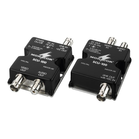
  9. Monacor Security SCU-100 User manual

Monacor Security SCU-100 User manual

AV-Übertragungssystem in
Einkabeltechnik
Bitte lesen Sie diese Anleitung vor der Installation gründlich
durch und heben Sie sie für ein späteres Nachlesen auf.
1 Verwendungsmöglichkeiten
Mit diesem Übertragungssystem lassen sich das Audio- und
Videosignal einer Überwachungskamera sowie die Span-
nungsversorgung für die Kamera über ein einziges Koaxialka-
bel übertragen. Bei Verwendung eines Kabels vom Typ RG-59
sind Leitungslängen von bis zu 500 m realisierbar.
2 Hinweise für den sicheren Gebrauch
Die Geräte (Sender, Empfänger, Netzgerät) entsprechen allen
relevanten Richtlinien der EU und sind deshalb mit gekenn-
zeichnet.
GDie Geräte sind nur zur Verwendung im Innenbereich ge-
eignet. Schützen Sie sie vor Tropf- und Spritzwasser, hoher
Luftfeuchtigkeit und Hitze (zulässiger Einsatztemperaturbe-
reich 0 – 40 °C).
GStellen Sie keine mit Flüssigkeit gefüllten Gefäße z. B.
Trinkgläser, auf die Geräte.
GNehmen Sie das Übertragungssystem nicht in Betrieb bzw.
ziehen Sie den Netzstecker sofort aus der Steckdose, wenn:
1. sichtbare Schäden am Netzgerät, Sender, Empfänger
oder an der Netzanschlussleitung vorhanden sind,
2. nach einem Sturz oder ähnlichem der Verdacht auf einen
Defekt besteht,
3. Funktionsstörungen auftreten.
Lassen Sie die Geräte in jedem Fall in einer Fachwerkstatt
reparieren.
WARNUNG Das Netzgerät wird mit lebensgefährlicher Netz-
spannung (230 V~) versorgt. Nehmen Sie des-
halb nie selbst Eingriffe am Gerät vor. Es be-
steht die Gefahr eines elektrischen Schlages.
2) Die Buchse LINK IN über ein 75-Ω-Koaxialkabel mit der
Buchse LINK OUT des Senders verbinden. Bei Verwen-
dung eines Kabels vom Typ RG-59 ist eine Länge von bis
zu 500 m möglich.
3) Den Kleinspannungsstecker des Netzgeräts in die Buchse
DC IN stecken und den Netzstecker in eine Steckdose
(230 V~/50 Hz).
4 Inbetriebnahme
Sobald am Empfänger die Versorgungsspannung anliegt,
leuchtet die Kontroll-LED grün.
1) Mit dem Schalter POWER am Empfänger das Übertra-
gungssystem einschalten. Die Kontroll-LEDs des Senders
und des Empfängers leuchten rot.
2) Leuchtet die Kontroll-LED des Senders grün, fließt kein
Versorgungsstrom zur Kamera (z. B. Kamera nicht ange-
schlossen oder defekt). Leuchtet die Kontroll-LED des Sen-
der gelb, ist die Betriebsspannung des Empfängers zu ge-
ring (< 15 V, z. B. beim Betrieb mit einem Akku anstelle des
Netzgeräts, wenn der Akku entladen ist).
3) Wird das Übertragungssystem längere Zeit nicht benötigt,
den Netzstecker des Netzgeräts aus der Steckdose ziehen.
Das Netzgerät verbraucht auch bei ausgeschalteter Anlage
einen geringen Strom.
5 Technische Daten
Stromversorgung: . . . . 18 – 27 V über beiliegendes Netz-
gerät an 230 V~/50 Hz/10 VA
Kameraversorgung: . . . 12 V , max. 500 mA
max. Kabellänge: . . . . 500 m bei Kabeltyp RG-59
Änderungen vorbehalten.
Single-Cable AV Transmission System
Please read these operating instructions carefully prior to in-
stallation and keep them for later reference.
1 Application
This transmission system allows both audio and video signal
transmission of a monitoring camera and power supply of the
camera via a single coaxial cable. In case of cable type
RG-59, a cable length of up to 500 m is possible.
2 Safety Notes
The units (transmitter, receiver, power supply unit) correspond
to all relevant directives of the EU and are therefore marked
with .
GThe units are suitable for indoor use only. Protect them
against dripping water and splash water, high air humidity,
and heat (admissible ambient temperature range 0 – 40 °C).
GDo not place any vessel filled with liquid on the units, e. g. a
drinking glass.
GDo not operate the transmission system or immediately dis-
connect the plug from the mains socket
1. if there is visible damage to the power supply unit, trans-
mitter, receiver or to the mains cable,
2. if a defect might have occurred after a unit was dropped
or suffered a similar accident,
3. if malfunctions occur.
In any case the units must be repaired by skilled personnel.
GNever pull the mains cable to disconnect the mains plug
from the socket, always seize the plug.
GA damaged mains cable of the power supply unit must be
replaced by skilled personnel only.
WARNING The power supply unit uses dangerous mains
voltage (230 V~). Leave servicing to skilled per-
sonnel only; inexpert handling may result in
electric shock.
GFor cleaning only use a dry, soft cloth, by no means chemi-
cals or water.
GNo guarantee claims for the units and no liability for any re-
sulting personal damage or material damage will be ac-
cepted if the units are used for other purposes than origi-
nally intended, if they are not correctly connected or
operated, or if they are not repaired in an expert way.
GImportant for U.K. Customers!
The wires in this mains lead are coloured in accordance
with the following code: blue = neutral, brown = live.
As the colours of the wires in the mains lead of this appliance
may not correspond with the coloured markings identifying
the terminals in your plug, proceed as follows:
1. The wire which is coloured blue must be connected to the
terminal in the plug which is marked with the letter N or
coloured black.
2. The wire which is coloured brown must be connected to the
terminal which is marked with the letter L or coloured red.
3 Connecting the Transmission System
The transmission system should be connected by skilled per-
sonnel only. The entire connection is shown in the figure
below. For connecting the camera and the monitor, BNC jacks
are provided on the transmitter and on the receiver.
3.1 Transmitter
1) Connect the video output of the monitoring camera to the
jack VIDEO IN and the audio output of the camera to the
jack AUDIO IN.
2) Connect the jack DC OUT to the input for the supply volt-
age of the camera. A matching low voltage cable with a
length of 1 m is supplied with the system.
If the units are to be put out of operation definitively,
take them to a local recycling plant for a disposal
which is not harmful to the environment.
3.2 Receiver
1) Connect the video input of the monitor to the jack VIDEO
OUT and the audio input of the monitor to the jack AUDIO
OUT.
2) Connect the jack LINK IN to the jack LINK OUT of the
transmitter via a 75 Ω coaxial cable. In case of cable type
RG-59, a length of up to 500 m is possible.
3) Connect the low voltage plug of the power supply unit to the
jack DC IN and the mains plug to a socket (230 V~/50 Hz).
4 Operation
As soon as the supply voltage is applied to the receiver, the
control LED shows green.
1) Switch on the transmission system with the POWER switch
on the receiver. The control LEDs of the transmitter and of
the receiver show red.
2)
If the control LED of the transmitter shows green, the camera
is not supplied with current (e. g. camera is not connected or is
defective). If the control LED of the transmitter shows yellow,
the operating voltage of the receiver is too low (< 15 V, e. g. if
the system is operated by rechargeable battery instead of the
power supply unit and this rechargeable battery is discharged).
3) If the transmission system is not used for a longer period,
disconnect the plug of the power supply unit from the mains
socket. Even with the system switched off, the power sup-
ply unit has a low current consumption.
5 Specifications
Power supply: . . . . . . . 18 – 27 V via supplied power sup-
ply unit at 230 V~/50 Hz/10 VA
Camera supply: . . . . . . 12 V , max. 500 mA
max. cable length: . . . . 500 m for cable type RG-59
Subject to technical modification.
SCU-100 Best.-Nr. 17.0910
VIDEO
OUT AUDIO
OUT
POWER
On/Off LINK IN
with
+DC OUT
DC IN
18-27V
R-POWER ON
G-STANDBY
NTSC/PAL INDOOR USE
SCU-100
VIDEO
IN AUDIO
IN
LINK OUT
with +DC IN
NTSC/PAL INDOOR USE
SCU-100
R-POWER ON
G-STANDBY
Y-POWER LOW
DC OUT
12V (0.8A)
®
POWER
O
I
H-HOLD V-HOLD BRIGHT CONTRAST
230V~/50Hz
VIDEO
AUDIO
AUDIO + VIDEO
VIDEO
AUDIO
12V
18–27V
18–27V
Sender / Transmitter Empfänger / Receiver
D A CH
GB
GZiehen Sie den Netzstecker nie am Kabel aus der Steck-
dose, fassen Sie immer am Stecker an.
GEin beschädigtes Netzkabel des Netzgeräts darf nur durch
eine Fachwerkstatt ersetzt werden.
GVerwenden Sie zum Reinigen nur ein trockenes weiches
Tuch, niemals Chemikalien oder Wasser.
GWerden die Geräte zweckentfremdet, nicht richtig an-
geschlossen, falsch bedient oder nicht fachgerecht repa-
riert, kann keine Haftung für daraus resultierende Sach-
oder Personenschäden und keine Garantie für die Geräte
übernommen werden.
3 Anschluss des Übertragungssystems
Das Übertragungssystem sollte nur durch eine qualifizierte
Fachkraft angeschlossen werden. Der gesamte Anschluss ist
in der untenstehenden Abbildung dargestellt. Für den An-
schluss der Kamera und des Monitors sind BNC-Buchsen am
Sender und am Empfänger vorhanden.
3.1 Sender
1) Den Videoausgang der Überwachungskamera an die
Buchse VIDEO IN anschließen und den Kamera-Audioaus-
gang an die Buchse AUDIO IN.
2) Die Buchse DC OUT mit dem Eingang für die Versorgungs-
spannung der Kamera verbinden. Ein passendes Klein-
spannungskabel von 1 m Länge liegt bei.
3.2 Empfänger
1) Den Videoeingang des Monitors an die Buchse VIDEO
OUT anschließen und den Monitor-Audioeingang an die
Buchse AUDIO OUT.
Sollen die Geräte endgültig aus dem Betrieb genom-
men werden, übergeben Sie sie zur umweltgerechten
Entsorgung einem örtlichen Recyclingbetrieb.
®
MONACOR INTERNATIONAL GmbH & Co. KG • Zum Falsch 36 • 28307 Bremen • Germany
Copyright©by MONACOR INTERNATIONAL. All rights reserved. A-0913.99.03.09.2011
®
Système de transmission audio/
vidéo, technique monocâble
Veuillez lire la présente notice avec attention avant lʼinstallation
et conservez-la pour pouvoir vous y reporter ultérieurement.
1 Possibilités dʼutilisation
Le système de transmission SCU-100 permet de transmettre
les signaux Audio et Vidéo dʼune caméra de surveillance ainsi
que lʼalimentation pour la caméra, via un câble coaxial unique.
Si vous utilisez un câble de type RG-59, vous pouvez at-
teindre des longueurs de câble de 500 m au plus.
2 Conseils dʼutilisation
Les appareils (émetteur, récepteur, bloc secteur) répondent à
toutes les directives nécessaires de lʼUnion européenne et
portent donc le symbole .
GLes appareils ne sont conçus que pour une utilisation en in-
térieur. Protégez-les des éclaboussures, de tout type de
projections dʼeau, dʼune humidité élevée de lʼair et de la
chaleur (température ambiante admissible 0 – 40 °C).
GEn aucun cas, vous ne devez pas poser dʼobjet contenant
du liquide ou un verre sur lʼappareil.
GNe les faites jamais fonctionner et débranchez-les immédia-
tement lorsque :
1. des dommages sur lʼémetteur, récepteur, bloc secteur ou
le cordon secteur apparaissent,
2. après une chute ou un cas similaire vous avez un doute
sur lʼétat de lʼappareil,
AVERTISSEMENT Le bloc secteur est alimenté par une
tension dangereuse en 230 V~. Ne tou-
chez jamais lʼintérieur de lʼappareil car,
en cas de mauvaise manipulation, vous
pouvez subir une décharge électrique.
3. des défaillances apparaissent.
Dans tous les cas, les dommages doivent être réparés par
un technicien spécialisé.
GNe débranchez jamais lʼappareil en tirant sur le cordon sec-
teur ; retirez toujours le cordon secteur en tirant la fiche.
GTout cordon secteur endommagé ne doit être remplacé que
par un technicien habilité.
GPour nettoyer les appareils, utilisez un chiffon sec et doux,
en aucun cas de produits chimiques ou dʼeau.
GNous déclinons toute responsabilité en cas de dommages
corporels ou matériels résultants si les appareils sont utili-
sés dans un but autre que celui pour lequel ils ont été
conçus, si les appareils ne sont pas correctement branchés,
utilisés ou réparés par une personne habilitée ; en outre, la
garantie deviendrait caduque.
3 Branchements
Le système de transmission ne doit être branché que par un
technicien habilité. Le schéma suivant présente le branche-
ment global. Les prises BNC sur lʼémetteur et le récepteur
sont prévues pour brancher la caméra et le moniteur.
3.1 Emetteur
1) Reliez la sortie vidéo de la caméra à la prise VIDEO IN et la
sortie audio de la caméra à la prise AUDIO IN.
2) Reliez la prise DC OUT à lʼentrée pour la tension dʼalimen-
tation de la caméra. Un cordon de 1 m de long est livré.
Lorsque les appareils sont définitivement retirés du
service, vous devez les déposer dans une usine de
recyclage de proximité pour contribuer à leur élimina-
tion non polluante.
3.2 Récepteur
1) Reliez lʼentrée vidéo du moniteur à la prise VIDEO OUT et
lʼentrée audio moniteur à la prise AUDIO OUT.
2) Reliez la prise LINK IN via un câble coaxial 75 Ω à la prise
LINK OUT de lʼémetteur. Si vous utilisez un câble de type
RG-59, vous pouvez atteindre 500 m.
3) Mettez la prise pour basse tension de lʼalimentation dans la
prise DC IN et reliez lʼensemble au secteur (230 V~/50 Hz).
4 Fonctionnement
Dès quʼune tension dʼalimentation est appliquée à lʼémetteur,
la LED verte brille.
1) Avec lʼinterrupteur POWER sur le récepteur, allumez le
système de transmission. Les LEDs de contrôle de lʼémet-
teur et du récepteur rouges brillent.
2) Si la LED verte de lʼémetteur brille, il nʼy a pas de courant
vers la caméra (caméra non branchée ou en panne). La
LED de lʼémetteur est jaune si la tension de fonctionne-
ment du récepteur est trop faible (< 15 V, par exemple si un
accu, utilisé à la place du bloc secteur est déchargé).
3) Si le système ne doit pas être utilisé pendant un certain
temps, débranchez-le. Même lorsque le système est éteint,
le bloc secteur a une faible consommation.
5 Caractéristiques techniques
Alimentation : . . . . . . . 18 – 27 V via bloc secteur à
230 V~/50 Hz/10 VA
Alimentation caméra : . 12 V , 500 mA max.
Longueur câble max. : . 500 m avec câble de type RG-59
Tout droit de modification réservé.
Sistema di trasmissione AV
con tecnica monocavo
Vi preghiamo di leggere attentamente le presenti istruzioni
prima dellʼinstallazione e di conservarle per un uso futuro.
1 Possibilità dʼimpiego
Con questo sistema di trasmissione si possono trasmettere i
segnali audio e video di una telecamera di sorveglianza non-
ché lʼalimentazione della telecamera mediante un unico cavo
coassiale. Impiegando un cavo del tipo RG-59 si possono su-
perare distanze fino a 500 metri.
2 Avvertenze di sicurezza
Gli apparecchi (trasmettitore, ricevitore, alimentatore) sono
conformi a tutte le direttive rilevanti dellʼUE e pertanto portano
la sigla .
GGli apparecchi sono adatti solo per lʼuso allʼinterno di locali.
Proteggerli dallʼacqua gocciolante e dagli spruzzi dʼacqua,
da alta umidità dellʼaria e dal calore (temperatura dʼimpiego
ammessa fra 0 e 40 °C).
GNon depositare sugli apparecchi dei contenitori riempiti di li-
quidi, p. es. bicchieri.
GNon mettere in funzione il sistema di trasmissione e stac-
care subito la spina rete se:
1. il trasmettitore, il ricevitore, lʼalimentatore o il cavo rete
presentano dei danni visibili;
2. dopo una caduta o dopo eventi simili sussiste il sospetto
di un difetto;
3. lʼapparecchio non funziona correttamente.
Per la riparazione rivolgersi sempre ad una officina compe-
tente.
AVVERTIMENTO Lʼalimentatore funziona con pericolosa
tensione di rete (230 V~). Non interve-
nire mai al suo interno. Esiste il pericolo
di una scarica elettrica.
GStaccare il cavo rete afferrando la spina, senza tirare il
cavo.
GIl cavo rete, se danneggiato, deve essere sostituito solo da
un laboratorio specializzato.
GPer la pulizia usare solo un panno asciutto; non impiegare
in nessun caso prodotti chimici o acqua.
GNel caso dʼuso improprio, di collegamenti sbagliati, dʼim-
piego scorretto o di riparazione non a regola dʼarte degli ap-
parecchi, non si assume nessuna responsabilità per even-
tuali danni consequenziali a persone o a cose e non si
assume nessuna garanzia per gli apparecchi.
3 Collegamento del sistema di trasmissione
Il sistema di trasmissione deve essere collegato solo da una
persona esperta e qualificata. La figura sottostante illustra i
collegamenti. Per il collegamento della telecamera e del moni-
tor sono presenti delle prese BNC sul trasmettitore e sul rice-
vitore.
3.1 Trasmettitore
1) Collegare lʼuscita video della telecamera con la presa
VIDEO IN e lʼuscita audio della telecamera con la presa
AUDIO IN.
2) Collegare la presa DC OUT con lʼingresso alimentazione
della telecamera. Un cavo adatto di 1 m di lunghezza si
trova in dotazione.
Se si desidera eliminare gli apparecchi definitiva-
mente, consegnarli per lo smaltimento ad unʼistitu-
zione locale per il riciclaggio.
3.2 Ricevitore
1) Collegare lʼingresso video del monitor con la presa VIDEO
OUT e lʼingresso audio del monitor con la presa AUDIO OUT.
2) Collegare la presa LINK IN con la presa LINK OUT del tra-
smettitore servendosi di un cavo coassiale 75 Ω. Impie-
gando un cavo del tipo RG-59 si possono superare di-
stanze fino a 500 metri.
3) Inserire la spina per basse tensioni dellʼalimentatore nella
presa DC IN e inserire la spina di rete in una presa
(230 V~/50 Hz).
4 Messa in funzione
Non appena il ricevitore è sotto tensione, si accende il LED
verde di controllo.
1) Con lʼinterruttore POWER sul ricevitore accendere il si-
stema. Si accendono i LED rossi di controllo del trasmetti-
tore e del ricevitore.
2) Se il LED di controllo del trasmettitore è verde, la corrente
non arriva alla telecamera (la telecamera non è collegata
oppure è difettosa). Se il LED di controllo è giallo, la ten-
sione di esercizio del ricevitore è troppo bassa (< 15 V,
p. es. nel caso di impiego di un accumulatore scarico usato
al posto dellʼalimentatore).
3) Se il sistema non viene utilizzato per un periodo prolun-
gato, staccare la spina dalla presa di rete. Infatti, lʼalimenta-
tore, anche se spento, consuma una piccola quantità di
corrente.
5 Dati tecnici
Alimentazione: . . . . . . . . . 18 – 27 V tramite alimentatore in
dotazione su 230 V~/50 Hz/10 VA
Alimentazione telecamera: 12 V , max. 500 mA
Lunghezza max. del cavo: 500 m, con cavo RG-59
Con riserva di modifiche tecniche.
SCU-100 Best.-Nr. 17.0910
VIDEO
OUT AUDIO
OUT
POWER
On/Off LINK IN
with
+DC OUT
DC IN
18-27V
R-POWER ON
G-STANDBY
NTSC/PAL INDOOR USE
SCU-100
VIDEO
IN AUDIO
IN
LINK OUT
with +DC IN
NTSC/PAL INDOOR USE
SCU-100
R-POWER ON
G-STANDBY
Y-POWER LOW
DC OUT
12V (0.8A)
®
POWER
O
I
H-HOLD V-HOLD BRIGHT CONTRAST
230V~/50Hz
VIDEO
AUDIO
AUDIO + VIDEO
VIDEO
AUDIO
12V
18–27V
18–27V
Emetteur / Trasmettitore Récepteur / Ricevitore
I
F B CH
®
MONACOR INTERNATIONAL GmbH & Co. KG • Zum Falsch 36 • 28307 Bremen • Germany
Copyright©by MONACOR INTERNATIONAL. All rights reserved. A-0913.99.03.09.2011
®

This manual suits for next models

1

Other Monacor Receiver manuals

Monacor JTS RU-8011D/5 User manual

Monacor

Monacor JTS RU-8011D/5 User manual

Monacor AV-5810R User manual

Monacor

Monacor AV-5810R User manual

Monacor Security AV-3030R User manual

Monacor

Monacor Security AV-3030R User manual

Monacor Security V-3030RDX User manual

Monacor

Monacor Security V-3030RDX User manual

Monacor AV-5810RDX User manual

Monacor

Monacor AV-5810RDX User manual

Monacor JTS RU-901G3/5 User manual

Monacor

Monacor JTS RU-901G3/5 User manual

Monacor WSA-10BT User manual

Monacor

Monacor WSA-10BT User manual

Monacor JTS IN-164R/5 User manual

Monacor

Monacor JTS IN-164R/5 User manual

Monacor PA LR-200 User manual

Monacor

Monacor PA LR-200 User manual

Monacor WAP-202RS User manual

Monacor

Monacor WAP-202RS User manual

Monacor JTS US-903DCPRO/5 User manual

Monacor

Monacor JTS US-903DCPRO/5 User manual

Monacor TXA-802SR User manual

Monacor

Monacor TXA-802SR User manual

Monacor Security SCU-100 User manual

Monacor

Monacor Security SCU-100 User manual

Monacor IRS-200R User manual

Monacor

Monacor IRS-200R User manual

Monacor WAP-202RS User manual

Monacor

Monacor WAP-202RS User manual

Monacor ATS-10R User manual

Monacor

Monacor ATS-10R User manual

Monacor JTS US-903DCPRO/5 User manual

Monacor

Monacor JTS US-903DCPRO/5 User manual

Monacor PA TXA-802MR User manual

Monacor

Monacor PA TXA-802MR User manual

Monacor WAP-204RS User manual

Monacor

Monacor WAP-204RS User manual

Monacor TXA-800R User manual

Monacor

Monacor TXA-800R User manual

Monacor WSA-20BT User manual

Monacor

Monacor WSA-20BT User manual

Monacor JTS RU-8012DB/5 User manual

Monacor

Monacor JTS RU-8012DB/5 User manual

Monacor WAP-202 User manual

Monacor

Monacor WAP-202 User manual

Monacor ATS-60R User manual

Monacor

Monacor ATS-60R User manual

Popular Receiver manuals by other brands

Yamaha RX-V3900 owner's manual

Yamaha

Yamaha RX-V3900 owner's manual

Icom IC-R5 instruction manual

Icom

Icom IC-R5 instruction manual

Alcor HD-2000 user manual

Alcor

Alcor HD-2000 user manual

Panasonic SA-HE75E Service manual

Panasonic

Panasonic SA-HE75E Service manual

Vemco VR60 Hardware manual

Vemco

Vemco VR60 Hardware manual

REUTER RDR54 Examples Manual

REUTER

REUTER RDR54 Examples Manual

Teac SDB420 owner's manual

Teac

Teac SDB420 owner's manual

Dish Network 118523 user guide

Dish Network

Dish Network 118523 user guide

Yamaha Aventage RX-A720 owner's manual

Yamaha

Yamaha Aventage RX-A720 owner's manual

Integra DTR-5.1 Service manual

Integra

Integra DTR-5.1 Service manual

Aiwa FR-C151 operating instructions

Aiwa

Aiwa FR-C151 operating instructions

Integra DTR-40.2 instruction manual

Integra

Integra DTR-40.2 instruction manual

Strong SRT 5202 user manual

Strong

Strong SRT 5202 user manual

Sony SAT-HD300 - High Definition Satellite... operating instructions

Sony

Sony SAT-HD300 - High Definition Satellite... operating instructions

Electra Bearcat BC3-L operating instructions

Electra

Electra Bearcat BC3-L operating instructions

Kramer 690R user manual

Kramer

Kramer 690R user manual

Frontier SKYTRAQ VENUS 838 manual

Frontier

Frontier SKYTRAQ VENUS 838 manual

Cambridge Audio AZUR 651A Service manual

Cambridge Audio

Cambridge Audio AZUR 651A Service manual

manuals.online logo
manuals.online logoBrands
  • About & Mission
  • Contact us
  • Privacy Policy
  • Terms and Conditions

Copyright 2025 Manuals.Online. All Rights Reserved.