manuals.online logo
Brands
  1. Home
  2. •
  3. Brands
  4. •
  5. Monacor
  6. •
  7. Speakers
  8. •
  9. Monacor EUL-50/SW User manual

Monacor EUL-50/SW User manual

Lautsprecherboxen-Paar
für 100-V- und 8-Ω-Betrieb
Bitte lesen Sie diese Anleitung vor der Installation
gründlich durch und heben Sie sie für ein späteres
Nachlesen auf.
1 Verwendungsmöglichkeiten
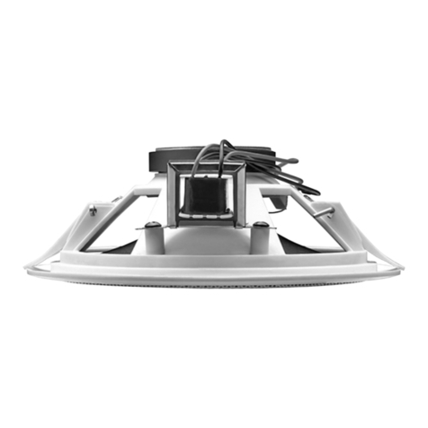
Diese 2-Wege-Bassreflex-Lautsprecherboxen sind
für den Einsatz in Beschallungsanlagen konzipiert.
Sie sind mit Übertragern für den Betrieb an 100-V-
Anlagen ausgestattet, können aber auch direkt an
niederohmige Verstärkerausgänge angeschlossen
werden. Der schwenkbare Standfuß lässt sich
auch als Halterung bei der Montage an einer Wand
oder Decke verwenden.
2 Wichtige Hinweise für den Gebrauch
Die Lautsprecherboxen entsprechen allen relevan-
ten Richtlinien der EU und sind deshalb mit 
gekennzeichnet.
GDie Lautsprecherboxen sind nur zur Verwen-
dung im Innenbereich geeignet. Schützen Sie
sie vor Tropf- und Spritzwasser, hoher Luftfeuch-
tigkeit und Hitze (zulässiger Einsatztemperatur-
bereich 0 – 40 °C).
GVerwenden Sie zum Reinigen nur ein trockenes,
weiches Tuch, nie Wasser oder Chemikalien.
GWerden die Lautsprecherboxen zweckentfrem-
det, nicht fachgerecht montiert, falsch ange-
schlossen oder überlastet, kann keine Haftung
für daraus resultierende Sach- oder Personen-
schäden und keine Garantie für die Lautspre-
cherboxen übernommen werden.
3 Installation
WARNUNG beim Einsatz in 100-V-Anlagen
Im Betrieb liegt berührungsgefähr-
liche Spannung bis 100 V an der Laut-
sprecherleitung an. Die Installation
darf nur durch Fachpersonal erfolgen.
Achten Sie auf die Belastung des ELA-Verstärkers
durch die Lautsprecher. Eine Überlastung kann
den Verstärker beschädigen! Die Summe der
Leistungen aller angeschlossenen Lautsprecher
darf die Verstärkerleistung nicht überschreiten.
Sollen die Lautsprecherboxen endgültig
aus dem Betrieb genommen werden, über-
geben Sie sie zur umweltgerechten Ent-
sorgung einem örtlichen Recyclingbetrieb.
1) Zuerst den Verstärker ausschalten, an den die
Lautsprecher angeschlossen werden sollen, da-
mit die Lautsprecherleitung spannungsfrei ist!
2) Die Lautsprecherboxen an geeigneter Stelle
aufstellen oder an einer Wand bzw. Decke mit
dem Standfuß festschrauben. Eine Bohrschab-
lone liegt bei. Die Boxen lassen sich durch ein
Kugelgelenk am Fuß optimal ausrichten. Ist das
Gelenk schwergängig, die vier Schrauben des
Gelenks mit dem beiliegenden Schlüssel etwas
lösen und nach dem Ausrichten fest anziehen.
3) Die Boxen an die Lautsprecherausgänge des
Verstärkers anschließen. Dabei darauf achten,
dass die Lautsprecher alle gleich gepolt werden
(roter Klemmanschluss = Pluspol, schwarzer
Anschluss = Minuspol).
4) Die gewünschte Nennleistung (Lautstärke) mit
dem Drehschalter auf der Rückseite einstellen
oder beim Betrieb an einem niederohmigen Ver-
stärkerausgang den Schalter in die Position
„8 Ω“ stellen.
Vorsicht! In der Position „8 Ω“ auf keinen Fall
den Lautsprecher in einer 100-V-Anlage betrei-
ben. Der Lautsprecher und eventuell auch der
Verstärker würden beschädigt.
Änderungen vorbehalten.
EUL-50/SW Bestellnummer 16.3270
EUL-50/WS Bestellnummer 16.3260
Pair of Speaker Systems
for 100 V and 8 Ω Operation
Please read these operating instructions carefully
prior to installation and keep them for later refer-
ence.
1 Applications
These 2-way bass reflex speaker systems are
designed for numerous PA systems. They are
equipped with transformers for operation at 100 V
systems, but may also be directly connected to
low-impedance amplifier outputs. The movable
base can be used as a support for mounting the
speaker systems to a wall or ceiling.
2 Important Notes
The speaker systems correspond to all relevant
directives of the EU and are therefore marked
with .
GThe speaker systems are suitable for indoor use
only. Protect them against dripping water and
splash water, high air humidity and heat (admis-
sible ambient temperature range: 0 – 40 °C).
GFor cleaning only use a dry, soft cloth; never use
water or chemicals.
GNo guarantee claims for the speaker systems
and no liability for any resulting personal damage
or material damage will be accepted if the
speaker systems are used for other purposes
than originally intended, if they are not properly
mounted, if they are not correctly connected or if
they are overloaded.
3 Mounting
WARNING when using 100 V systems
During operation, there is a hazard of
contact with a voltage of up to 100 V
at the speaker cable. Installation must
be made by skilled personnel only.
Observe the load of the PA amplifier by the
speaker systems. The amplifier may be damaged
when overloaded! The total power of all speaker
systems connected must not exceed the amplifier
power.
If the speaker systems are to be put out of
operation definitively, take them to a local
recycling plant for a disposal which is not
harmful to the environment.
1) First switch off the amplifier to which the spea-
ker systems are to be connected so that the
speaker cable will not carry any voltage!
2) Place the speaker systems at an appropriate
location or mount them to a wall or ceiling using
the base. A drilling jig is supplied. Use the ball
joint at the base to align the speaker systems as
desired. If the ball joint is stiff, slightly loosen the
four screws using the hex key provided, align
the speaker systems and then firmly retighten
the screws.
3) Connect the speaker systems to the speaker
outputs of the amplifier. Make sure that all spea-
ker systems have the same polarity (red termi-
nal = positive pole, black terminal = negative
pole).
4) Adjust the power rating desired (volume) by
means of the rotary switch located on the rear
side, or, for operation at a low-impedance ampli-
fier output, set the switch to the position “8 Ω”.
Caution! Never operate the speaker at a 100 V
system when the rotary switch has been set to
“8 Ω”. The speaker and maybe also the amplifier
will be damaged.
Subject to technical modification.
MONACOR INTERNATIONAL GmbH & Co. KG • Zum Falsch 36 • 28307 Bremen • Germany
Copyright ©by MONACOR INTERNATIONAL. All rights reserved. A-1571.99.01.05.2014
®
D A CH
GB
Technische Daten Specifications EUL-50/SW • EUL-50/WS
Nennbelastbarkeit
100-V-Betrieb
8-Ω-Betrieb
Power rating
100 V operation
8 Ω operation
16/8/4/2 WRMS
30 WRMS/60 WMAX
Frequenzbereich Frequency range 60 – 20 000 Hz
Mittl. Schalldruck (1 W/1 m) SPL (1 W/1 m) 89 dB
Maximaler Nennschalldruck Max. rated SPL 103 dB
Lautsprecherbestückung Speaker configuration 1 × 13-cm-Tieftöner (5″), 1 × Kalottenhöchtoner
1 × 13 cm bass speaker (5″), 1 × dome tweeter
Abmessungen Dimensions 160 × 260 × 160 mm
Gewicht Weight 2,3 kg
Anschlüsse Connections LS-Klemmanschluss • speaker terminal
ELECTRONICS FOR SPECIALISTS ELECTRONICS FOR SPECIALISTS ELECTRONICS FOR SPECIALISTS ELECTRONICS FOR SPECIALISTS ELECTRONICS FOR SPECIALISTS ELECTRONICS
Paire dʼenceintes pour
fonctionnement ligne
100 V et 8 Ω
Veuillez lire la présente notice avec attention avant
l'installation et conservez-la pour pouvoir vous y
reporter ultérieurement.
1 Possibilités d'utilisation
Ces enceintes bass-reflex 2 voies sont conçues
pour une utilisation dans des installations de sono-
risation. Elles sont équipées de transformateurs
pour fonctionnement dans des installations 100 V,
elles peuvent également être directement reliées à
des sorties amplificateur basse impédance. Le
pied orientable peut être utilisé comme support
pour un montage sur un mur ou à un plafond.
2 Conseils importants dʼutilisation
Les enceintes répondent à toutes les directives
nécessaires de l'Union européenne et portent donc
le symbole .
GLes enceintes ne sont conçues que pour une uti-
lisation en intérieur. Protégez-les des éclabous-
sures, de tout type de projections d'eau, dʼune
humidité élevée de l'air et de la chaleur (tempé-
rature ambiante admissible 0 – 40 °C).
GPour le nettoyage, utilisez uniquement un chiffon
sec et doux, en aucun cas de produits chimiques
ou d'eau.
G
Nous déclinons toute responsabilité en cas de dom-
mages matériels ou corporels résultants si les en-
ceintes sont utilisées dans un but autre que celui
pour lequel elles ont été conçues, si elles ne sont pas
correctement installées ou branchées ou sʼil y a sur-
charge ; en outre, la garantie deviendrait caduque.
3 Installation
AVERTISSEMENT pour utilisation dans des installa-
tions 100 V
Pendant le fonctionnement, une
tension de contact dangereuse
jusquʼà 100 V est présente sur le
câble haut-parleur. Seul un personnel qualifié
peut effectuer l'installation.
Faites attention à la charge de l'amplificateur PA
par les haut-parleurs. Une surcharge peut endom-
mager l'amplificateur ! La somme des puissances
Lorsque les enceintes sont définitivement
retirées du service, vous devez les déposer
dans une usine de recyclage adaptée pour
contribuer à leur élimination non polluante.
1) Eteignez tout dʼabord lʼamplificateur auquel les
enceintes doivent être reliées pour que le câble
haut-parleur ne soit pas porteur de tension !
2) Placez les enceintes à un endroit adapté ou vis-
sez-les sur un mur ou à un plafond avec le pied.
Un gabarit de perçage est livré. Pour orienter les
enceintes, utilisez lʼarticulation à rotule sur le
pied. Si lʼarticulation est difficile à déplacer, des-
serrez un peu les quatre vis de lʼarticulation avec
la clé livrée, orientez les enceintes puis revissez.
3) Reliez les enceintes aux sorties haut-parleur de
lʼamplificateur. Veillez à ce que toutes les en-
ceintes aient la même polarité (borne rouge
= pôle plus, borne noir = pôle moins).
4) Réglez la puissance nominale voulue (volume)
avec le sélecteur rotatif sur la face arrière ou,
pour un fonctionnement à une sortie amplifica-
teur basse impédance, mettez le sélecteur sur
la position “8 Ω”.
Attention ! Sur la position “8 Ω”, ne faites pas
fonctionner une enceinte dans une installation
100 V. Lʼenceinte et éventuellement lʼamplifica-
teur pourraient être endommagés.
Tout droit de modification réservé.
de l'ensemble des haut-parleurs reliés ne doit pas
dépasser la puissance de l'amplificateur.
EUL-50/SW Bestellnummer 16.3270
EUL-50/WS Bestellnummer 16.3260
Coppia di casse acustiche per il
funzionamento con uscita audio
100 V e con 8 Ω
Vi preghiamo di leggere attentamente le presenti
istruzioni prima dell'installazione e di conservarle
per un uso futuro.
1 Possibilità d'impiego
Queste casse bassreflex a 2 vie sono previste per
l'impiego in impianti di sonorizzazione. Sono equi-
paggiate con trasformatori per il funzionamento in
impianti di 100 V, ma possono essere collegate
anche con uscite a bassa impedenza degli amplifi-
catori. Il piede orientabile può essere usato come
supporto per il montaggio a una parete o al soffitto.
2 Avvertenze importanti per l'uso
Le casse acustiche sono conformi a tutte le diret-
tive rilevanti dellʼUE e pertanto portano la sigla .
GLe casse acustiche sono previste solo per lʼuso
allʼinterno di locali. Proteggerle dall'acqua goc-
ciolante e dagli spruzzi d'acqua, da alta umidità
dell'aria e dal calore (temperatura dʼimpiego
ammessa fra 0 e 40 °C).
GPer la pulizia usare solo un panno morbido,
asciutto; non impiegare in nessun caso acqua o
prodotti chimici.
GNel caso dʼuso improprio, di montaggio non a
regola d'arte, di collegamenti sbagliati o di
sovraccarico delle casse, non si assume nes-
suna responsabilità per eventuali danni conse-
quenziali a persone o a cose e non si assume
nessuna garanzia per le casse.
3 Installazione
AVVERTIMENTO
in caso d'impiego in impianti a
100 V
Durante il funzionamento, nel
cavo di collegamento è presente
una tensione fino a 100 V, perico-
losa in caso di contatto. L'installazione deve
essere eseguita solo da personale specializzato.
Tener presente anche il carico dell'amplificatore
PA da parte degli altoparlanti. Un sovraccarico
può danneggiare l'amplificatore! La somma delle
potenze di tutti gli altoparlanti collegati non deve
superare la potenza dell'amplificatore.
Se si desidera eliminare le casse acusti-
che definitivamente, consegnarle per lo
smaltimento ad unʼistituzione locale per il
riciclaggio.
1) Per prima cosa spegnere l'amplificatore al quale
si devono collegare le casse, perché la linea
degli altoparlanti sia senza tensione!
2) Collocare le casse in un punto adatto o avvitarle
a una parete o al soffitto per mezzo del piede. In
allegato si trova una dima per i fori. Grazie allo
snodo sferico è possibile orientare le casse in
modo ottimale. Se lo snodo è duro, allentare leg-
germente le quattro viti dello snodo per mezzo
della chiave in dotazione e stringere bene le viti
nuovamente dopo l'orientamento delle casse.
3) Collegare le casse con le uscite per altoparlanti
dell'amplificatore. Fare attenzione all'identica
polarità di tutti gli altoparlanti (morsetto rosso =
polo positivo, morsetto nero = polo negativo).
4) Tramite l'interruttore rotante sul retro, impostare
la potenza nominale (volume) oppure, utiliz-
zando un'uscita a bassa impedenza dell'amplifi-
catore, portare l'interruttore in posizione “8 Ω”.
Attenzione! In posizione “8 Ω” non usare in
nessun caso l'altoparlante in un impianto con
uscita audio di 100 V. L'altoparlante e eventual-
mente anche l'amplificatore verrebbero danneg-
giati.
Con riserva di modifiche tecniche.
MONACOR INTERNATIONAL GmbH & Co. KG • Zum Falsch 36 • 28307 Bremen • Germany
Copyright ©by MONACOR INTERNATIONAL. All rights reserved. A-1571.99.01.05.2014
®
I
F B CH
ELECTRONICS FOR SPECIALISTS ELECTRONICS FOR SPECIALISTS ELECTRONICS FOR SPECIALISTS ELECTRONICS FOR SPECIALISTS ELECTRONICS FOR SPECIALISTS ELECTRONICS
Caractéristiques techniques Dati tecnici EUL-50/SW • EUL-50/WS
Puissance nominale
Fonctionnement 100 V
Fonctionnement 8 Ω
Potenza nominale
Funzionamento 100 V
Funzionamento 8 Ω
16/8/4/2 WRMS
30 WRMS/60 WMAX
Bande passante Gamma di frequenze 60 – 20 000 Hz
Pression sonore moyenne
(1 W/1 m)
Pressione sonora media
(1 W/1 m) 89 dB
Pression sonore nominale
maximale
Pressione sonora nominale
mass. 103 dB
Configuration enceinte Altoparlanti 1 × grave 13 cm (5″), 1 × aigu à dôme
1 × woofer 13 cm (5″), 1 × tweeter a cupola
Dimensions Dimensioni 160 × 260 × 160 mm
Poids Peso 2,3 kg
Branchements Contatti bornier haut-parleur • morsetti per altoparlanti
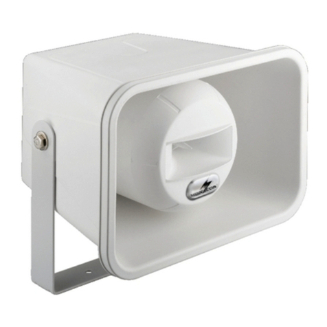
Pareja de Recintos para
Funcionamiento a 100 V y a 8 Ω
Lea atentamente estas instrucciones de funciona-
miento antes de instalar el aparato y guárdelas
para usos posteriores.
1 Aplicaciones
Estos recintos Bass Reflex de 2 vías están diseña-
dos para varios sistemas de megafonía. Están
equipados con transformadores para funcionar en
sistemas de 100 V pero también se pueden conec-
tar directamente a salidas de baja impedancia de
un amplificador. La base móvil se puede utilizar
como soporte para montar los recintos en una
pared o en un techo.
2 Notas Importantes
Los recintos cumplen con todas las directivas rele-
vantes de la UE y por lo tanto están marcados con
el símbolo .
GLos recintos están adecuados para utilizarlos
sólo en interiores. Protéjalos de goteos y salpi-
caduras, elevada humedad del aire y calor (tem-
peratura ambiente admisible: 0 – 40 ºC).
GUtilice sólo un paño suave y seco para la limpieza;
no utilice nunca ni agua ni productos químicos.
GNo podrá reclamarse garantía o responsabilidad
alguna por cualquier daño personal o material
resultante si los recintos se utilizan para otros
fines diferentes a los originalmente concebidos,
si no se montan o conectan correctamente o si
se sobrecargan.
3 Montaje
ADVERTENCIA si utiliza sistemas de 100 V
Durante el funcionamiento, hay
peligro de contacto con un voltaje
de hasta 100 V en el cable de alta-
voz. Sólo un técnico debe realizar
la instalación.
Preste atención a la carga del amplificador de
megafonía con los recintos. ¡Una sobrecarga
podría dañar el amplificador! La potencia total de
todos los recintos conectados no puede exceder
la potencia del amplificador.
Si va a poner los recintos fuera de servicio
definitivamente, llévelos a la planta de
reciclaje más cercana para que su elimi-
nación no perjudique el medioambiente.
1) ¡Primero desconecte el amplificador al que se
conectarán los recintos de modo que el cable de
altavoz no contenga ningún voltaje!
2) Coloque los recintos en un lugar apropiado o
móntelos en una pared o techo utilizando la
base. Se entrega una plantilla de montaje. Uti-
lice la articulación de rótula de la base para ali-
near los recintos según convenga. Si la articula-
ción de rótula está rígida, afloje lentamente los
cuatro tornillos utilizando la llave hexagonal
entregada, alinee los recintos y luego fije de
nuevo los tornillos con firmeza.
3) Conecte los recintos a las salidas de altavoz del
amplificador. Asegúrese de que todos los recin-
tos tienen la misma polaridad (terminal rojo
= polo positivo, terminal negro = polo negativo).
4) Ajuste la potencia deseada (volumen) mediante
el interruptor rotatorio localizado en la parte
posterior o, para funcionar con una salida de
amplificador de baja impedancia, ajuste el inte-
rruptor en la posición “8 Ω”.
¡Precaución! No utilice nunca el altavoz con un
sistema de 100 V cuando el interruptor rotatorio
esté ajustado en “8 Ω”. Podría dañar el altavoz
y posiblemente el amplificador.
Sujeto a modificaciones técnicas.
EUL-50/SW Bestellnummer 16.3270
EUL-50/WS Bestellnummer 16.3260
Para zestawów głośnikowych
100 V i 8 Ω
Przed rozpoczęciem użytkowania prosimy o zapo-
znanie się z instrukcją i zachowanie jej do wglądu.
1 Zastosowanie
Niniejsze 2-drożne zestawy głośnikowe bass reflex
przeznaczone są do zastosowań w systemach PA.
Wyposażone są w transformatory umożliwiające
pracę w systemach 100 V, ale możliwe jest ich pod-
łączanie również do wzmacniacza niskoimpe-
dancyjnego. Dzięki ruchomej podstawie, będącej
także uchwytem montażowym, możliwa jest ich
instalacja do ściany oraz pod sufitem.
2 Środki bezpieczeństwa
Zestawy głośnikowe spełniają wszystkie wymaga-
nia norm UE dzięki temu zostały oznaczone sym-
bolem .
GZestawy głośnikowe przeznaczone są tylko do
zastosowań wewnętrznych. Należy chronić go
przez wodą, dużą wilgotnością oraz wysokimi
temperaturami (dopuszczalny zakres 0 – 40 °C).
GDo czyszczenia należy używać suchej i miękkiej
ściereczki, nie używać wody ani środków che-
micznych.
GProducent i dostawca nie ponoszą odpowiedzial-
ności za powstałe szkody: uszkodzenia sprzętu
bądź obrażenia użytkownika, jeżeli głośnik był
używany niezgodnie z przeznaczeniem, niepo-
prawnie zainstalowany, podłączony lub przecią-
żony.
3 Montaż
UWAGA dotycząca pracy w systemach 100 V
W czasie pracy, na złączach wystę-
puje niebezpieczne wysokie napięcie
100 V. Instalacja powinna być wyko-
nywana wyłącznie przez przeszko-
lony personel!
Należy zwrócić uwagę na obciążenie wzmacnia-
cza przez głośniki. Przeciążenie wzmacniacza
spowoduje jego uszkodzenie! Sumaryczna moc
głośników nie może przekraczać mocy wzmac-
niacza.
Jeśli urządzenia nie będą już więcej uży-
wane, wskazane jest przekazanie ich do
miejsca utylizacji odpadów, aby zostały
zniszczone bez szkody dla środowiska.
1) Przed przystąpieniem do podłączania głośni-
ków należy odłączyć zasilanie całego systemu
PA, aby kabel głośnikowy nie znajdował się pod
napięciem!
2) Przymocować zestaw głośnikowy do ściany/
sufitu poprzez podstawę montażową, w odpo-
wiednim miejscu. W komplecie znajdują się
kołki rozporowe. Za pomocą przegubu kulo-
wego ustawić zestaw głośnikowy pod żądanym
kątem. Dla ułatwienia, na czas ustawiania,
można poluzować cztery śruby imbusowe.
3) Podłączyć zestawy głośnikowe do wyjść głośni-
kowych wzmacniacza. Zwrócić uwagę, aby
wszystkie zestawy głośnikowe miały jednakową
polaryzację (czerwony terminal = dodatni bie-
gun, czarny terminal = ujemny biegun).
4) Ustawić odpowiednią moc (głośność) za po-
mocą przełącznika obrotowego na tylnej stronie
obudowy. W przypadku pracy ze wzmacnia-
czem niskoimpedancyjnym, ustawić przełącznik
na pozycję “8 Ω”.
Uwaga! Nie wolno podłączać zestawu głoś-
nikowego ustawionego na pracę w trybie “8 Ω”
do wzmacniacza 100 V. Wzmacniacz i głośnik
mogą ulec uszkodzeniu.
Z zastrzeżeniem możliwości zmian.
MONACOR INTERNATIONAL GmbH & Co. KG • Zum Falsch 36 • 28307 Bremen • Germany
Copyright ©by MONACOR INTERNATIONAL. All rights reserved. A-1571.99.01.05.2014
®
ELECTRONICS FOR SPECIALISTS ELECTRONICS FOR SPECIALISTS ELECTRONICS FOR SPECIALISTS ELECTRONICS FOR SPECIALISTS ELECTRONICS FOR SPECIALISTS ELECTRONICS
E
PL
Especificaciones Specyfikacja EUL-50/SW • EUL-50/WS
Potencia nominal
Funcionamiento a 100 V
Funcionamiento a 8 Ω
Moc
Tryb 100 V
Tryb 8 Ω
16/8/4/2 WRMS
30 WRMS/60 WMAX
Rango de frecuencias Pasmo przenoszenia 60 – 20 000 Hz
SPL (1 W/1 m) SPL (1 W/1 m) 89 dB
SPL máx. Max poziom SPL 103 dB
Configuración de altavoz Wyposażenie
1 × altavoz de graves de 13 cm (5″), 1 × tweeter de cúpula
1 × 13 cm (5″) głośnik basowy,
1 × kopułkowy głośnik wysokotonowy
Dimensiones Wymiary 160 × 260 × 160 mm
Peso Waga 2,3 kg
Conexiones Złącza Terminal de altavoz • Terminale głośnikowe

This manual suits for next models

3

Other Monacor Speakers manuals

Monacor PAB-6WP User manual

Monacor

Monacor PAB-6WP User manual

Monacor EDL-24 User manual

Monacor

Monacor EDL-24 User manual

Monacor TM-45 User manual

Monacor

Monacor TM-45 User manual

Monacor EDL-603 User manual

Monacor

Monacor EDL-603 User manual

Monacor ESP-5U User manual

Monacor

Monacor ESP-5U User manual

Monacor ETS-8100TW/SW User manual

Monacor

Monacor ETS-8100TW/SW User manual

Monacor ESP-60/WS User manual

Monacor

Monacor ESP-60/WS User manual

Monacor IT-40 User manual

Monacor

Monacor IT-40 User manual

Monacor ETS-210TW/WS User manual

Monacor

Monacor ETS-210TW/WS User manual

Monacor 0170970 User manual

Monacor

Monacor 0170970 User manual

Monacor TM-45 User manual

Monacor

Monacor TM-45 User manual

Monacor IT-10M User manual

Monacor

Monacor IT-10M User manual

Monacor ATT-442ST User manual

Monacor

Monacor ATT-442ST User manual

Monacor PA EDL-65TW User manual

Monacor

Monacor PA EDL-65TW User manual

Monacor IT-40 User manual

Monacor

Monacor IT-40 User manual

Monacor KU-516 User manual

Monacor

Monacor KU-516 User manual

Monacor CARPOWER NEOVOX-130 User manual

Monacor

Monacor CARPOWER NEOVOX-130 User manual

Monacor EDL-68/WS User manual

Monacor

Monacor EDL-68/WS User manual

Monacor TM-25 User manual

Monacor

Monacor TM-25 User manual

Monacor EDL-42HQ User manual

Monacor

Monacor EDL-42HQ User manual

Monacor SPS-40S User manual

Monacor

Monacor SPS-40S User manual

Monacor MKA-60SET/SW User manual

Monacor

Monacor MKA-60SET/SW User manual

Monacor PAB-6WP/WS User manual

Monacor

Monacor PAB-6WP/WS User manual

Monacor EUL-26/SW User manual

Monacor

Monacor EUL-26/SW User manual

Popular Speakers manuals by other brands

Toshiba TY-SP3 Operation manual

Toshiba

Toshiba TY-SP3 Operation manual

Denon Envoi user guide

Denon

Denon Envoi user guide

Novik Neo NK-66S instruction manual

Novik Neo

Novik Neo NK-66S instruction manual

Microlab FC330 user manual

Microlab

Microlab FC330 user manual

AUSTRALIAN MONITOR QF6WRC Installation and operation manual

AUSTRALIAN MONITOR

AUSTRALIAN MONITOR QF6WRC Installation and operation manual

Behringer Ultrabass BA410 Technical specifications

Behringer

Behringer Ultrabass BA410 Technical specifications

Episode ES-500-SAT-4 owner's manual

Episode

Episode ES-500-SAT-4 owner's manual

SWELLPRO MP1 user manual

SWELLPRO

SWELLPRO MP1 user manual

JBL CONTROL X owner's manual

JBL

JBL CONTROL X owner's manual

Pyle PKRK8 user manual

Pyle

Pyle PKRK8 user manual

Pioneer S-DJ50X operating instructions

Pioneer

Pioneer S-DJ50X operating instructions

Akai CEU7300-BT instruction manual

Akai

Akai CEU7300-BT instruction manual

Panasonic SC-NA07 operating instructions

Panasonic

Panasonic SC-NA07 operating instructions

EUROLIVE B312D operating instructions

EUROLIVE

EUROLIVE B312D operating instructions

Bushnell OUTDOORSMAN OUTM1BTS owner's guide

Bushnell

Bushnell OUTDOORSMAN OUTM1BTS owner's guide

MSE Audio Rockustics ESCAPE Series owner's manual

MSE Audio

MSE Audio Rockustics ESCAPE Series owner's manual

Phonic NEXUS 540 user manual

Phonic

Phonic NEXUS 540 user manual

Tangent Spectrum X5BT user manual

Tangent

Tangent Spectrum X5BT user manual

manuals.online logo
manuals.online logoBrands
  • About & Mission
  • Contact us
  • Privacy Policy
  • Terms and Conditions

Copyright 2025 Manuals.Online. All Rights Reserved.