manuals.online logo
Brands
  1. Home
  2. •
  3. Brands
  4. •
  5. Monacor
  6. •
  7. Speakers
  8. •
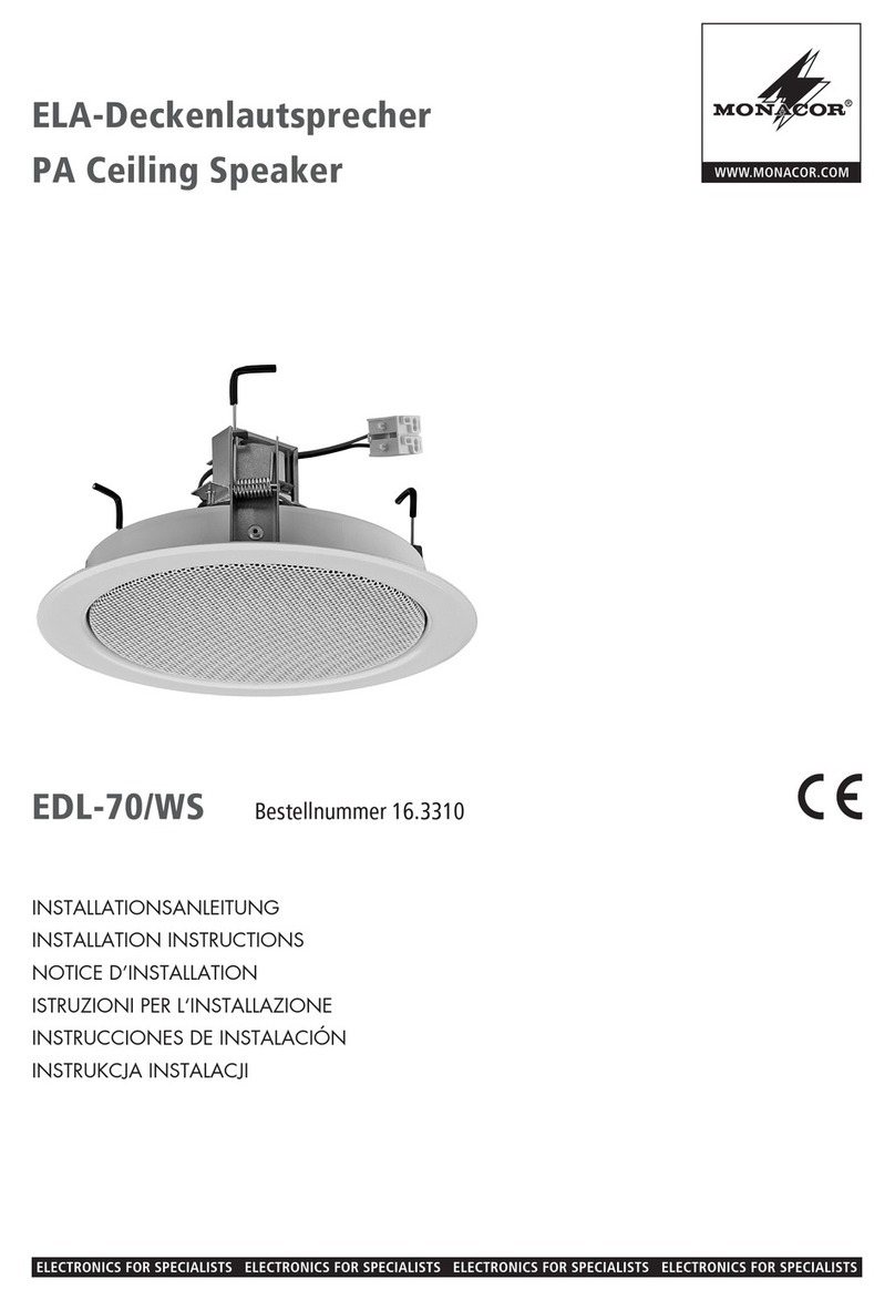
  9. Monacor EDL-68/WS User manual

Monacor EDL-68/WS User manual

®
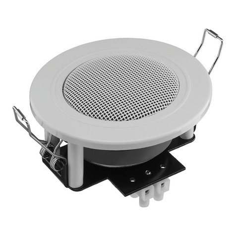
ELA-Deckenlautsprecher
Bitte lesen Sie diese Anleitung vor der Installation
gründlich durch und heben Sie sie für ein späteres
Nachlesen auf.
1 Verwendungsmöglichkeiten
Dieser Deckenlautsprecher dient zur Beschallung mit
Sprache und Hintergrundmusik. Er ist speziell für den
Einsatz in ELA-Anlagen konzipiert, die mit 100-V-
Technik arbeiten. Durch die zweiteilige Ausführung
des Lautsprechers (Halterahmen und Lautsprecher-
chassis) ist die Montage sehr einfach.
2 Wichtige Hinweise für den Gebrauch
Der Lautsprecher entspricht allen erforderlichen Richt-
linien der EU und deshalb mit gekennzeichnet.
GDer Lautsprecher ist nur zur Verwendung im Innen-
bereich geeignet. Schützen Sie ihn vor Tropf- und
Spritzwasser, hoher Luftfeuchtigkeit und Hitze (zu-
lässiger Einsatztemperaturbereich 0 – 40 °C).
GVerwenden Sie zum Reinigen nur ein trockenes,
weiches Tuch, auf keinen Fall Wasser oder Chemi-
kalien.
GWird der Lautsprecher zweckentfremdet, nicht fach-
gerecht montiert, falsch angeschlossen oder über-
lastet, kann keine Haftung für daraus resultierende
Sach- oder Personenschäden und keine Garantie
für den Lautsprecher übernommen werden.
3 Montage
1) Das Lautsprecherchassis bis zum Anschlag dre-
hen, sodass es aus dem Halterahmen genommen
werden kann.
2) Die drei Haltefedern des Rahmens zum
Spannen nach oben drücken und in die
Arretierung (Pfeil) einhaken.
VORSICHT! Beim Spannen der Federn und
Lösen (Montageschritt 4) besteht durch die
starke Federkraft Verletzungsgefahr. Hal-
ten Sie Ihre Finger nicht zwischen Rahmen
und gespannter Feder!
3) In die Decke ein Loch mit einem Durchmesser von
200 mm sägen.
4) Den Halterahmen in das Deckenloch einsetzen
und die Federn wieder vorsichtig aus der Arretie-
rung lösen, sodass sie zurückschnellen und den
Rahmen in der Decke halten.
5) Das Fangseil des Lautsprecherchassis im Inneren
der Decke oder am Halterahmen (z. B. an der Arre-
tierung einer Haltefeder) befestigen, damit das
Chassis gegen Herabfallen gesichert ist.
6) Den Anschluss nach Kapitel 4 durchführen.
7) Das Lautsprecherchassis in den Rahmen einsetzen
und bis zum Anschlag drehen, damit es fest sitzt.
Soll der Lautsprecher endgültig aus dem
Betrieb genommen werden, übergeben Sie
ihn zur umweltgerechten Entsorgung einem
örtlichen Recyclingbetrieb.
4 Elektrischer Anschluss
1) Vor dem elektrischen Anschluss des Lautsprechers
die ELA-Anlage komplett ausschalten, damit die
100-V-Audioleitung vom ELA-Verstärker span-
nungsfrei ist!
2) Den Lautsprecher so an die 100-V-Audioleitung
vom ELA-Verstärker anschließen, dass die gewün-
schte Nennleistung (Lautstärke) erreicht wird:
schwarzer und weißer Draht = 3 WRMS
schwarzer und roter Draht = 6 WRMS
3) Beim Anschluss von mehreren Lautsprechern
darauf achten, dass die Lautsprecher alle gleich
gepolt werden (z. B. schwarzer Draht = Minusan-
schluss) und dass der ELA-Verstärker nicht über-
lastet wird.
Änderungen vorbehalten.
WARNUNG Im Betrieb liegt berührungsgefährliche
Spannung bis 100 V an der Anschluss-
leitung an.
Die Installation darf nur durch Fachper-
sonal erfolgen.
Achten Sie auf die Belastung des ELA-Verstärkers
durch die Lautsprecher. Eine Überlastung kann den
Verstärker beschädigen! Die Summe der Leistungen
aller angeschlossenen Lautsprecher darf die Verstär-
kerleistung nicht überschreiten.
EDL-68/WS Best.-Nr. 16.2340
PA Ceiling Speaker
Please read these operating instructions carefully
prior to installing the unit and keep them for later use.
1 Applications
This ceiling speaker serves for PA applications with
speech and background music. It is especially
designed for use in PA systems operating with 100 V
technique. Due to the two-part design of the speaker
(holding frame and speaker) the mounting is very
easy.
2 Important Notes
The speaker corresponds to all required directives of
the EU and is therefore marked with .
GThe speaker is only suitable for indoor applications.
Protect it against dripping water and splash water,
high air humidity, and heat (admissible ambient tem-
perature range 0 – 40 °C).
GFor cleaning only use a dry, soft cloth, never use
chemicals or water.
GNo guarantee claims for the speaker and no liability
for any resulting personal damage or material dam-
age will be accepted if the speaker is used for other
purposes than originally intended, if it is not correctly
mounted and connected, or if it is overloaded.
If the speaker is to be put out of operation
definitively, take it to a local recycling plant for
a disposal which is not harmful to the envi-
ronment.
3 Mounting
1) Turn the speaker up to the stop so that it can be
taken out of the holding frame.
2) Press the three holding springs of the frame
upwards for tightening and hook each spring
into the corresponding catch (arrow).
CAUTION! When tightening and releasing
the springs (mounting step 4), there is a risk
of injury due to the high tension of the
springs. Do not put your fingers between
frame and spring under tension!
3) Saw a hole with a diameter of 200 mm into the
ceiling.
4) Insert the holding frame into the ceiling hole and
carefully release the springs from the catch so that
they rebound and hold the frame in the ceiling.
5) Fix the safety rope of the speaker inside the ceiling
or at the holding frame (e. g. at the catch of a hold-
ing spring) so that the speaker is secured against
falling down.
6) Make the connection according to chapter 4.
7) Insert the speaker into the frame and turn it up to
the stop for a tight fit.
4 Electrical Connection
1) Prior to the electrical connection of the speaker,
switch off the PA system completely so that the
100 V audio cable of the PA amplifier does not carry
any voltage!
2) Connect the speaker to the 100 V audio cable of the
PA amplifier so that the desired rated power
(volume) is reached;
black and white wires = 3 WRMS
black and red wires = 6 WRMS
3) When connecting several speakers, make sure that
all speakers have the same polarity (e. g. black wire
= negative connection) and that the PA amplifier is
not overloaded.
Subject to technical modification.
WARNING During operation, there is a hazard of
contact with a voltage of up to 100 V at
the connection cable.
The installation must only be made by
skilled personnel.
Pay attention to the load of the PA amplifier by the
speakers. An overload may damage the amplifier!
The total power of all speakers connected must not
exceed the amplifier power.
Ø 200
62.5
Ø 220
2.5
min. 1
max. 30
MONACOR INTERNATIONAL GmbH & Co. KG • Zum Falsch 36 • 28307 Bremen • Germany
Copyright©by MONACOR INTERNATIONAL. All rights reserved. A-0802.99.02.08.2011
®
D A CH
GB
Technische Daten Specifications EDL-86/WS
Frequenzbereich Frequency range 100 – 19 000 Hz
Nennbelastbarkeit (an 100 V)
schwarz – weiß
schwarz – rot
Power rating (at 100 V)
black – white
black – red
3WRMS
6WRMS
Abmessungen siehe Zeichnung
(Werte in mm)
Dimensions see drawing
(values in mm)
Gewicht Weight 1300 g
®
Haut-parleur de plafond Public Adress
Veuillez lire la présente notice avec attention avant
lʼinstallation et conservez-la pour pouvoir vous y
reporter ultérieurement.
1 Possibilités dʼutilisation
Ce haut-parleur sert pour des applications de Public
Adress en sonorisation de discours et musique de
fond. Il est spécialement conçu pour une utilisation
dans des installations de Public Adress fonctionnant
en ligne 100 V. La conception du haut-parleur en deux
éléments (cadre de maintien et haut-parleur) facilite
grandement le montage.
2 Conseils importants dʼutilisation
Le haut-parleur répond à toutes les directives néces-
saires de lʼUnion Européenne et porte donc le sym-
bole .
GLʼappareil nʼest conçu que pour une utilisation en
intérieur. Protégez-le des éclaboussures, de tout
type de projections dʼeau, dʼune humidité dʼair éle-
vée et de la chaleur (température ambiante admis-
sible 0 – 40 °C).
GPour le nettoyage, utilisez uniquement un chiffon
sec et doux, en aucun cas de produits chimiques ou
dʼeau.
GNous déclinons toute responsabilité en cas de dom-
mages matériels ou corporels résultants si le haut-
parleur est utilisé dans un but autre que celui pour
lequel il a été conçu, sʼil nʼest pas correctement
monté, branché ou sʼil y a surcharge ; en outre, la
garantie deviendrait caduque.
3 Montage
1) Tournez le haut-parleur jusquʼà la butée de telle
sorte quʼil puisse être retiré du cadre de maintien.
2) Poussez vers le haut les trois ressorts du
cadre pour serrer et faites-les entrer dans
lʼencoche (flèche).
PRECAUTION ! Il y a risque de blessure à
cause des forces des ressorts lorsque vous
les serrez et les relâchez (point de mon-
tage 4). Ne mettez jamais vos doigts entre
le cadre et les ressorts sous tension.
3) Découpez un trou de diamètre 200 mm dans le pla-
fond.
4) Placez le cadre de montage dans le trou du plafond
et desserrez avec précaution les ressorts de leur
encoche pour quʼils rebondissent et maintiennent
le cadre dans le plafond.
5) Fixez la corde du haut-parleur dans lʼintérieur du
plafond ou sur le cadre (par exemple sur lʼencoche
dʼun ressort) pour que le haut-parleur ne puisse
pas tomber.
6) Effectuez le branchement comme décrit dans le
chapitre 4.
Lorsque le haut-parleur est définitivement
retiré du service, vous devez le déposer dans
une usine de recyclage adaptée pour contri-
buer à son élimination non polluante.
7) Placez le haut-parleur dans le cadre et tournez jus-
quʼà la butée pour bien le maintenir.
4 Branchement électrique
1) Avant dʼeffectuer les branchements électriques du
haut-parleur, débranchez complètement lʼinstalla-
tion Public Adress pour que le câble audio 100 V de
lʼamplificateur PAne soit pas conducteur de tension.
2) Reliez le haut-parleur au câble audio 100 V de lʼam-
plificateur Public Adress pour atteindre la puis-
sance nominale souhaitée (volume) :
fils noir et blanc = 3 WRMS
fils noir et rouge = 6 WRMS
3) Si plusieurs haut-parleurs sont branchés, veillez à
ce que tous les haut-parleurs aient la même pola-
rité (fil noir = branchement moins) et que lʼamplifi-
cateur ne soit pas en surcharge.
Tout droit de modification réservé.
AVERTISSEMENT Pendant le fonctionnement, une
tension de contact dangereuse
jusquʼà 100 V est présente au
câble de branchement.
Seul un personnel qualifié peut
effectuer lʼinstallation.
Faites attention à la charge de lʼamplificateur PA par
les haut-parleurs. Une surcharge peut endommager
lʼamplificateur. La somme des puissances de lʼen-
semble des haut-parleurs reliés ne doit pas dépasser
la puissance de lʼamplificateur.
EDL-68/WS Best.-Nr. 16.2340
Diffusore PA da soffitto
Vi preghiamo di leggere attentamente le presenti istru-
zioni prima dellʼinstallazione e di conservarle per un
uso futuro.
1 Possibilità dʼimpiego
Questo diffusore da soffitto serve per la sonorizza-
zione con lingua parlata e con musica di sottofondo. È
stato realizzato specialmente per lʼimpiego in impianti
PA che lavorano con uscita audio 100 V. Grazie alla
struttura in due parti del diffusore (telaio e altopar-
lante), il montaggio è molto semplice.
2 Avvertenze importanti per lʼuso
Il diffusore è conforme a tutte le direttive richieste
dellʼUE e pertanto porta la sigla .
GIl diffusore è previsto solo per lʼuso allʼinterno di
locali. Proteggerlo dallʼacqua gocciolante e dagli
spruzzi dʼacqua, da alta umidità dellʼaria e dal calore
(temperatura dʼimpiego ammessa fra 0 e 40 °C).
GPer la pulizia usare solo un panno morbido, asciutto;
non impiegare in nessun caso prodotti chimici o
acqua.
GNel caso dʼuso improprio, di montaggio scorretto, di
collegamenti sbagliati o di sovraccarico del diffu-
sore, non si assume nessuna responsabilità per
eventuali danni consequenziali a persone o a cose
e non si assume nessuna garanzia per il diffusore.
3 Montaggio
1) Girare lʼaltoparlante fino allʼarresto in modo da
poterlo togliere dal telaio.
2) Premere le tre molle del telaio in alto per
metterle sotto tensione e agganciarle al dis-
positivo di bloccaggio (freccia).
ATTENZIONE! Mettendo sotto tensione le
molle e persbloccarle (passo n. 4 del mon-
taggio), per via della loro forza elastica
esiste il rischio di ferirsi. Non tenere le dita
fra telaio e molla tesa!
3) Applicare nel soffitto un buco con diametro di
200 mm.
4) Inserire il telaio nellʼapertura del soffitto e sbloccare
le molle con molta attenzione dal loro bloccaggio in
modo che possano scattare tenendo il telaio fermo
nel soffitto.
5) Fissare la fune di sicurezza dellʼaltoparlante allʼin-
terno del soffitto o sul telaio (p. es. al bloccaggio di
una molla) per proteggere lʼaltoparlante dalla
caduta.
6) Eseguire il collegamento come descritto nel capi-
tolo 4.
7) Inserire lʼaltoparlante nel telaio e girarlo fino allʼar-
resto per garantire un fissaggio sicuro.
Se si desidera eliminare il diffusore definiti-
vamente, consegnarlo per lo smaltimento ad
unʼistituzione locale per il riciclaggio.
4 Collegamento elettrico
1) Prima di eseguire i collegamenti elettrici spegnere
completamente lʼimpianto PA per togliere la ten-
sione dalla linea 100 V dellʼamplificatore PA!
2) Collegare lʼaltoparlante con la linea 100 V dellʼam-
plificatore PA in modo tale da ottenere la potenza
nominale (il volume) desiderata:
conduttore nero e bianco = 3 WRMS
conduttore nero e rosso = 6 WRMS
3) Collegando più altoparlanti fare attenzione allʼiden-
tica polarità di tutti gli altoparlanti (p. es. conduttore
nero = negativo) e di non sovraccaricare lʼamplifi-
catore PA.
Con riserva di modifiche tecniche.
AVVERTIMENTO Durante il funzionamento, al cavo
di collegamento è presente una
tensione fino a 100 V, pericolosa
per il contatto.
Lʼinstallazione deve essere fatta
solo da personale specializzato.
Fare attenzione al carico dellʼamplificatore PA da
parte degli altoparlanti. Il sovraccarico può danneg-
giare lʼamplificatore! La somma della potenze di tutti
gli altoparlanti collegati non deve superare la potenza
dellʼamplificatore.
Ø 200
62.5
Ø 220
2.5
min. 1
max. 30
MONACOR INTERNATIONAL GmbH & Co. KG • Zum Falsch 36 • 28307 Bremen • Germany
Copyright©by MONACOR INTERNATIONAL. All rights reserved. A-0802.99.02.08.2011
®
F
I
Caractéristiques techniques Dati tecnici EDL-86/WS
Bande passante Gamma di frequenze 100 – 19 000 Hz
Puissance nominale (sous 100 V)
noir – blanc
noir – rouge
Potenza nominale (con 100 V)
nero – bianco
nero – rosso
3WRMS
6WRMS
Dimensions, voir dessin
(valeurs en mm)
Dimensioni vedi disegno
(valori in mm)
Poids Peso 1300 g
®
Altavoz de techo para megafonía
Lea atentamente estas instrucciones de funciona-
miento antes de instalar el aparato y consérvelas para
usos posteriores.
1 Aplicaciosnes
Este altavoz de techo sirve para aplicaciones de
megafonía con habla y música de fondo. Está dise-
ñado especialmente para sistemas de megafonía con
línea de 100 V. Debido al diseño en dos piezas del
altavoz (estructura de sujeción y altavoz), el montaje
es muy fácil.
2 Notas de interés
El altavoz corresponde con todas las directivas reque-
ridas por la UE y por lo tanto está marcado con el sím-
bolo .
GEl altavoz está adecuado sólo para aplicaciones en
interiores. Protéjalo contra goteos y salpicaduras,
elevada humedad del aire y calor (temperatura
ambiente admisible: 0 – 40 ºC).
GPara su limpieza utilice sólo un paño seco y suave,
no utilice nunca agua o productos químicos.
GNo podrá reclamarse garantía o responsabilidad
alguna para el altavoz por cualquier daño personal
o material si éste se utiliza para otros fines diferen-
tes a los originalmente concebidos, si no se instala
o conecta correctamente o si se sobrecarga.
3 Montaje
1) Extraiga el altavoz hacia el tope para que se pueda
sacar de la estructura de sujeción.
2) Pulse los tres muelles de sujeción de la
estructura hacia arriba para apretar y colo-
carlos cada uno en el enganche correspon-
diente (vea la flecha).
¡PRECAUCIÓN! Cuando apriete o libere
los muelles (paso 4 del montaje) existe
peligro de lesión por la fuerte tensión de
los muelles. No coloque sus dedos entre la
estructura y el muelle en tensión.
3) Haga un agujero en el techo con un diámetro de
corte de 200 mm.
4) Inserte la estructura de sujeción en el agujero del
techo y libere con precaución los muelles de los
enganches para que reboten y aguanten la
estructura en el techo.
5) Fije la cuerda de seguridad del altavoz en el interior
del techo o en la estructura de sujeción (p.ej. en el
enganche de un muelle) para que el altavoz esté
asegurado contra caídas.
6) Haga la conexión tal y como se explica en el apar-
tado 4.
7) Inserte el altavoz en la estructura y apriételo hasta
el stop para un encaje perfecto.
Si se va a poner el altavoz fuera de servicio
definitivamente, llévelo a la planta de reci-
claje más cercana para que su eliminación
no perjudique el medioambiente.
4 Conexión Eléctrica
1) Antes de la conexión eléctrica del altavoz, desco-
necte completamente el sistema de megafonía
para que el cable de audio de 100 V del amplifica-
dor no contenga ningún voltaje.
2) Conecte el altavoz al cable de 100 V del amplifica-
dor de modo que se alcance la potencia deseada
(volumen);
Cables blanco y negro = 3 WRMS
Cables rojo y negro = 6 WRMS
3) Cuado conecte varios altavoces, asegúrese de que
todos los altavoces tienen la misma polaridad (p.ej.
cable negro = polo negativo) y de que el amplifica-
dor no se sobrecarga.
Sujeto a modificaciones técnicas.
ADVERTENCIA Durante el funcionamiento existe el
peligro de contacto con un voltaje
de hasta 100 V en el cable de
conexión.
La instalación debe realizarla solo
el personal cualificado.
Preste atención a la carga del amplificador para los
altavoces. Una sobrecarga podría dañar el amplifica-
dor. La potencia total de todos los altavoces no
puede exceder la potencia del amplificador.
EDL-68/WS Best.-Nr. 16.2340
Głośnik sufitowy PA
Przed rozpoczęciem instalacji proszę dokładnie
zapoznać się z niniejszą instrukcją i zachować ją do
wglądu.
1 Zastosowanie
Głośnik sufitowy przeznaczony jest do emisji sygnału
mowy oraz tła muzycznego w systemach PA. Przysto-
sowany jest do pracy w technice 100 V. Dzięki dwu-
częściowej budowie (ramka i głośnik) i specjalnym
zaczepom na ramce montażowej, montaż głośnika
jest bardzo łatwy.
2 Ważne informacje
Głośnik spełnia wszystkie wymagania norm UE dzięki
temu został oznaczony symbolem .
GGłośnik przeznaczony jest tylko do zastosowań
wewnętrznych. Należy chronić go przez wodą, dużą
wilgotnością oraz wysokimi temperaturami (dopu-
szczalny zakres 0 – 40 °C).
GDo czyszczenia należy używać suchej i miękkiej
ściereczki, nie używać wody ani środków che-
micznych.
GDostawca oraz producent nie ponoszą odpowiedzi-
alności za ewentualnie wynikłe szkody materialne
lub uszczerbki na zdrowiu, jeśli urządzenie było
używane niezgodnie z przeznaczeniem, zostało nie-
poprawnie zainstalowane lub było poddawane
naprawom przez nieautoryzowany personel.
3 Montaż
1) Przekręcić głośnik do końca, aż odczepi się od
ramki montażowej.
2) Podciągnąć do góry sprężyny zaczepów
montażowych na ramce i zaczepić je w
oznaczonym miejscu (strzałka).
UWAGA! Przy zwalnianiu zaczepów (krok 4),
należy uważać na palce, gdyż siła naciągu
sprężyn jest bardzo duża i może spowodo-
wać uszkodzenia ciała!
3) W odpowiednim miejscu w suficie wyciąć okrągły
otwór o średnicy 200 mm.
4) Umieścić ramkę montażową w otworze i ostrożnie
zwolnić sprężyny zaczepów, ramka zostanie
zamontowana w suficie.
5) Przymocować linkę zabezpieczającą głośnika do
elementu konstrukcyjnego wewnątrz sufitu lub do
ramki montażowej, aby zabezpieczyć głośnik przed
wypadnięciem.
6) Podłączyć kabel zgodnie z rozdziałem 4.
7) Wsunąć głośnik do ramki montażowej i przekręcić
do końca w celu zamontowania.
Jeśli urządzenie nie będzie już więcej
używane, wskazane jest przekazanie go do
miejsca utylizacji odpadów, aby zostało
zniszczone bez szkody dla środowiska.
4 Podłączanie
1) Przed przystąpieniem do podłączania głośników
należy odłączyć zasilanie całego systemu PA, aby
kabel głośnikowy 100 V nie znajdował się pod
napięciem!
2) Podłączyć głośnik do kabla głośnikowego 100 V od
wzmacniacza tak, aby uzyskać żądaną moc (gło-
śność) głośnika;
czarna i biała żyła = 3 WRMS
czarna i czerwona żyła = 6 WRMS
3) Przy podłączaniu kilku głośników, upewnić się że
wszystkie zostały podłączone z jednakową polary-
zacją (np. czarny – ujemny) oraz że wzmacniacz
nie jest przeciążony.
Z zastrzeżeniem możliwości zmian.
OSTRZEŻENIE W czasie pracy, na złączach wystę-
puje zagrożenie porażenia wyso-
kim napięciem 100 V.
Instalacja powinna być wykony-
wana wyłącznie przez przeszko-
lony personel.
Należy zwrócić uwagę na obciążenie wzmacniacza
przez głośniki. Przeciążenie wzmacniacza spowo-
duje jego uszkodzenie! Sumaryczna moc głośników
nie może przekraczać mocy wzmacniacza.
Ø 200
62.5
Ø 220
2.5
min. 1
max. 30
MONACOR INTERNATIONAL GmbH & Co. KG • Zum Falsch 36 • 28307 Bremen • Germany
Copyright©by MONACOR INTERNATIONAL. All rights reserved. A-0802.99.02.08.2011
®
E
PL
Especificaciones Specyfikacja EDL-86/WS
Banda pasante Pasmo przenoszenia 100 – 19 000 Hz
Potencia (a 100 V)
negro – blanco
negro – rojo
Moc (przy 100 V)
czarny – biały
czarny – czerwony
3WRMS
6WRMS
Dimensiones ver dibujo
(valores en mm)
Wymiary na rysunku
(w mm)
Peso Waga 1300 g

This manual suits for next models

2

Other Monacor Speakers manuals

Monacor EDL-35 User manual

Monacor

Monacor EDL-35 User manual

Monacor MKA-60SET/SW User manual

Monacor

Monacor MKA-60SET/SW User manual

Monacor PA ESP-17/WS User manual

Monacor

Monacor PA ESP-17/WS User manual

Monacor EDL-65TW User manual

Monacor

Monacor EDL-65TW User manual

Monacor EDL-706 User manual

Monacor

Monacor EDL-706 User manual

Monacor IT-250TW User manual

Monacor

Monacor IT-250TW User manual

Monacor WALL-05DTM/WS User manual

Monacor

Monacor WALL-05DTM/WS User manual

Monacor MKA-50SET/SW User manual

Monacor

Monacor MKA-50SET/SW User manual

Monacor IT-350 ⁄ EN User manual

Monacor

Monacor IT-350 ⁄ EN User manual

Monacor PA EDL-605 User manual

Monacor

Monacor PA EDL-605 User manual

Monacor EDL-603 User manual

Monacor

Monacor EDL-603 User manual

Monacor TM-22 User manual

Monacor

Monacor TM-22 User manual

Monacor IT-15EN User manual

Monacor

Monacor IT-15EN User manual

Monacor ETS-210TW/WS User manual

Monacor

Monacor ETS-210TW/WS User manual

Monacor TM-6 User manual

Monacor

Monacor TM-6 User manual

Monacor EDL-22/WS User manual

Monacor

Monacor EDL-22/WS User manual

Monacor CARPOWER NEOVOX-130 User manual

Monacor

Monacor CARPOWER NEOVOX-130 User manual

Monacor NR-22KS User manual

Monacor

Monacor NR-22KS User manual

Monacor EDL-605 User manual

Monacor

Monacor EDL-605 User manual

Monacor EX-1 User manual

Monacor

Monacor EX-1 User manual

Monacor TM-45 User manual

Monacor

Monacor TM-45 User manual

Monacor ESP-90/WS User manual

Monacor

Monacor ESP-90/WS User manual

Monacor IRS-200TXA User manual

Monacor

Monacor IRS-200TXA User manual

Monacor ESP-63/WS User manual

Monacor

Monacor ESP-63/WS User manual

Popular Speakers manuals by other brands

Anchor MiniVox owner's manual

Anchor

Anchor MiniVox owner's manual

Adam F5 Operation manual

Adam

Adam F5 Operation manual

LAMAX Sounder2 user manual

LAMAX

LAMAX Sounder2 user manual

Bowers & Wilkins CCM616 Owner's manual and warranty

Bowers & Wilkins

Bowers & Wilkins CCM616 Owner's manual and warranty

Blackweb BWA18AA008 manual

Blackweb

Blackweb BWA18AA008 manual

Sonance Visual Performance Series PAINTING INSTRUCTION

Sonance

Sonance Visual Performance Series PAINTING INSTRUCTION

QSC AD-S282H user manual

QSC

QSC AD-S282H user manual

VL Audio WS-64 user manual

VL Audio

VL Audio WS-64 user manual

Bowers & Wilkins WP 1 owner's manual

Bowers & Wilkins

Bowers & Wilkins WP 1 owner's manual

Ryobi RBT18-0 manual

Ryobi

Ryobi RBT18-0 manual

Ecler ARQISi Series user manual

Ecler

Ecler ARQISi Series user manual

NGS WILDSKA 2 user manual

NGS

NGS WILDSKA 2 user manual

Crown Micro CMBS-501 user manual

Crown Micro

Crown Micro CMBS-501 user manual

Genesis 350 Specifications

Genesis

Genesis 350 Specifications

KYE Systems Corp. Genius SP700 Service manual

KYE Systems Corp.

KYE Systems Corp. Genius SP700 Service manual

DS18 ZXI-44 owner's manual

DS18

DS18 ZXI-44 owner's manual

Bogen A2 Specifications

Bogen

Bogen A2 Specifications

Emotiva LCR SERIES user manual

Emotiva

Emotiva LCR SERIES user manual

manuals.online logo
manuals.online logoBrands
  • About & Mission
  • Contact us
  • Privacy Policy
  • Terms and Conditions

Copyright 2025 Manuals.Online. All Rights Reserved.