manuals.online logo
Brands
  1. Home
  2. •
  3. Brands
  4. •
  5. Monosem
  6. •
  7. Farm Equipment
  8. •
  9. Monosem MECA 3-2005 User manual

Monosem MECA 3-2005 User manual

NOTICE SEMOIRS
PLANTER MANUAL
УООО О ЭУАА
Notice de montage,
Réglage,
Entretien
нструкции по
сборке,
регулировке и
техническому
обслу иванию
Bedienungsanleitung,
Einstellung,
Wartung
Assembly,
Adjustment and
Maintenance
Instructions
NOTICE SEMOIRS
PLANTER MANUAL
УООО О ЭУАА
MECA 3-2005
MECA 3-2005
MECA 3 - 2005
Réf. 90781.05
1
Cette notice est à lire attentivement avant
montage et utilisation, elle est à conserver
soigneusement. Pour plus de renseigne-
ments, ou en cas de réclamation, vous
pouvez appeler l'usine RIBOULEAU
MONOSEM, numéro de téléphone en
dernière page.
L'identification et l'année de fabrication de
votre semoir se trouvent sur la boîte de
distances.
This manual should be read carefully
before assembling and operation. It
should be kept in safe place. For further
information or in the event of claims, you
may call the RIBOULEAU MONOSEM
factory at the phone number given on the
last page of this manual.
The identification and manufacturers plate
on your planter is to be found on the gear-
box of the machine.
Diese Bedienungsanleitung ist vor jeder
Montage und vor jedem Betrieb sorgfâltig zu
lesen und auf jeden Fall beizubehalten. Für
jede zusätzliche Auskunft bzw. bei
Beanstandungen rufen Sie bitte das Werk
RIBOULEAU MONOSEM unter der auf der
letzten Seite angegebenen Telefonnummer
an! Die Identifizierung und das Baujahr Ihrer
Sämaschine finden Sie auf dem Wechsel-
getriebe.
Это руководство по эксплуатации должно быть
прочитано перед сборкой и использованием
сеялки. Оно находится в безопасном месте. а
дополнительной ин ормацией или в других
случаях вы можете позвонить на завод
RIBOULEAU MONOSEM, теле оны даны на
последней странице руководства.
ерийный и заводской номера вашей машины
выбиты на пластине, которая находится на
коробке передач точного высева.
Vous venez d'acquérir un appareil fiable
mais ATTENTION à son utilisation !...
2 PRÉCAUTIONS POUR RÉUSSIR VOS SEMIS :
• Choisissez une vitesse de travail raisonnable adaptée
aux conditions et à la régularité désirée.
• Assurez-vous dès la mise en route puis de temps en temps
de la DISTRIBUTION, de l'ENTERRAGE, de la DENSITÉ.
You have just purchased a reliable machine
but BE CAREFUL using it !...
2 PRECAUTIONS FOR SUCCESSFUL PLANTING :
• Choose a reasonable working speed adapted to the field
conditions and desired accuracy.
• Check proper working of the seed metering, seed PLACEMENT,
SPACING and DENSITY before planting and from time to
time during planting.
Sie haben gerade eine zuverlässige Maschine gekauft !
ACHTEN SIE auf eine sorgfältige Bedienung !...
ANLEITUNG ZUR GUTEN AUSSAAT :
•Wählen Sie eine vernünftige Arbeitsgeschwindigkeit, die der
Bodenbeschaffenheit angepaßt ist.
•Prüfen Sie die Sämaschine auf Ablagegenauigkeit bereits
vor der Arbeit und von Zeit zu Zeit während des Säens.
ы купили наде ную машину
но УЬ ООО при использовании ее!...
2 ОА Я УОО ОА:
• ыберите разумную рабочую скорость, приспособленную к
полевым условиям и желательной точности высева.
•роверьте надлежащую работу высевающего аппарата,
А, А  ОУ А семян перед
посевом и время от времени при посеве.
Les instructions de cette notice sont destinées à nos semoirs MONOSEM ; elles ne concernent pas les sous ensembles utilisés seuls ou sur d'autres appareils (boîtiers...)
Montage général des châssis
General frame asssembly
Montage des Haüptrahmens
Общая сборка рам
1-2-3-4
Rayonneurs
Row markers
Spuranzeiger
ядные маркеры
2-3
Boîtier de distribution
Metering box
Wechselgetriebe
ысевающий аппарат
7
Élément MECA 3
Planter metering unit MECA 3
Säelement MECA 3
ысевающая секция MECA 3
5-6
Distances et densités de semis
Seed spacing gearbox
Wechselgetriebe für die Pflanzenabstände
оробка передач для изменения
интервала между семенами
8
Fertiliseur
Fertilizer
Reihendüngerstreuer
Устройство для внесения удобрений
11-12
Microgranulateur
Microgranular applicator
Microgranulatstreuer
Устройство для внесения микрогранул
10
MONTAGES
et REGLAGES
ASSEMBLY
INSTALLATION
MONTAGE
EINSTELLUNG
нструкции по
сборке,
регулировке и
техническому
обслуживанию
PAGES
ENTRETIEN ET DEPANNAGE
ADVICE FOR MAINTENANCE AND TROUBLE SHOOTING
RATSCHLÄGE FÜR WARTUNG UND STÖRUNGSBESEITIGUNG
еисправности и способы их устранения
15
PIECES DE RECHANGE
SPARE PARTS
ERSATZTEILE
аталог запасных частей
16
23
ÉQUIPEMENTS DIVERS - MISCELLANEOUS EQUIPMENT
COMPTEUR D'HECTARES
HECTARE COUNTER
Rép. Désignation
1534 a Contre-bride largeur 120 mm
4317.1 Tube fourreau longueur 25 mm
4328 Roulement longueur 25 mm
4329 a Circlip de roulement
4365 a Axe d'attelage semi-automatique (A 128 S)
4366 c Taquet d'axe d'attelage
4369 Douille d'articulation taquet d'attelage
4370 Ressort de taquet
4381 d Compteur d'hectares alternatif
4494 Bride centrale de châssis couplé
4495 Bride latérale de châssis couplé
4496 Bloc latéral d'attelage renforcé de châssis couplé
4497 a Bloc latéral d'attelage semi-automatique châssis couplé
4498 a Support turbine pour châssis couplé
4499 3e point central châssis couplé
4535.2 Broche d'attelage ø 28 mm n°2
4549 Embout plastique de protection
4603 a Barre nue d'attelage avancé semi-auto, long 2,20 m
4603.1a Barre longueur 2,60 m
4604.1 support turbine côté gauche d'attelage avancé
4604.2 Support turbine côté droit d'attelage avancé
4605 a Guide corde d'attelage avancé
4606 Bras de liaison d'attelage avancé complet
4606.1 Bras de liaison partie femelle seulement
4606.2 Bras de liaison partie mâle seulement
4612 Contre-bride largeur 140 mm
4612.2 Contre-bride largeur 140 mm, 6 trous
4640 d Bloc support dents piocheuses
4641 c Support compteur alternatif
4645 Came de commande compteur alternatif
4646 Levier de commande compteur alternatif
4647 Bride de serrage en U (fil ø 12 mm)
4648 a Protecteur de compteur
Rép. Désignation
4669 Contre-bride largeur 60 mm pour barre de 127
4700.1 1/2 coquille support aimant
4701.1 Aimant de compteur électronique
4704 Porte capteur
4705 Couvercle de capteur
4722 Axe de couvercle
4723 Compteur électronique avec capteur
6090 Circlip d'arrêt ø 6
9236 a Contre-bride de guide corde
9557 Goupille clip
11254 Soc pointu de dent fouilleuse rigide
11280 Montant de dent fouilleuse
11476.1 Goupille clip ø 9 mm avec chaînette
11550 Ressort nu
11551 Chape support outil
11552 Bride support dent piocheuse
ATTELAGES
COUPLÉS
COUPLED HITCHES DENTS PIOCHEUSES
DIGGING TINES
Électronique Mécanique
ATTELAGE AVANCÉ
ADVANCED FRAME
221
MONTAGE GÉNÉRAL
GENERAL ASSEMBLY
ALLGEMEINE MONTAGE
ОАЯ ОА
• Barre porte-outils longueur 3 m
• Axe de roues longueur 2,70 m
• Axe d’éléments longueur 2,95 m
• 2 roues pneu 500 x 15
• Rayonneurs manuels (bras long. 1,30 m) (fig. 12)
• Barre porte-micro 2,50 m avec 2 supports.
• лина основной рамы 3,0 м
• лина колесного вала 2,70 м
• лина вала привода высевающих секций 2,95 м
• 2 приводных колеса 500х15
• ядные ручные маркеры (длина 1,3 м) (рис.12)
• ама для микровысева 2,50 м на 2-х опорах.
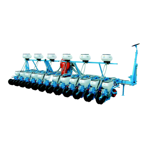
Châssis rigide monobarre 12 rangs
Single bar 12 row frame
Einzelrahmen 12 reihig
ельная рама на 12 рядков
Châssis rigide 6 rangs
Single bar 6 row frame
Einzelrahmen 6 reihig
ельная рама на 6 рядков
• Barre porte-outils longueur 6,10 m
• Axe de roues longueur 5,20 m
• Axe d’éléments longueur 6 m
• 4 roues pneu 500 x 15
• Rayonneurs hydrauliques
(cadre 1,05 m – Tube femelle 1 m – tube mâle 1 m) (fig. 16)
• Barre porte-micro en 2 longueurs de 2 m avec 4 supports et un entraînement.
• лина основной рамы 6,10 м
• лина колесного вала 5,20 м
• лина вала привода высевающих секций 6,0 м
• 4 приводных колеса 500х15
• ядные гидравлические маркеры (квадрат 1,05 м – наружная труба 1 м –
внутренняя ртуба 1 м) (рис.16)
• ве рамы для микровысева по 2 м на 4-х опорах.
CHARIOT DE TRANSPORT CARRE 127
TRANSPORT CARRIAGE WITH 5" X 5" FRAME
ATTELAGE DOUBLE BARREATTELAGE TRIPLE BARRE
Rép. Désignation
1534.a Contre bride 4 trous lg 120 ép. 12 mm (entraxe 80)
4365.a Axe d'attelage semi-automatique (A128S) 0,75 m
4365.1 Axe d'attelage semi-automtique Lg 1,060 m
4366.c Taquet d'axe d'attelage
4489 Entretoise courte de liaison châssis rigide
4490.1 Bride plate renforcée châssis rigide
4491.3 Bras latéral gauche châssis rigide semi-auto
4491.4 Bras latéral droit châssis rigide semi-auto
4516.3 Plaque latérale gauche attelage semi-auto spéciale chariot transport
4516.4 Plaque latérale droit attelage semi-auto spéciale chariot transport
4517 Embout de barre porte outils
4535.4 Axe supérieur attelage ø 25 lg 136 mm
4606.1 Bras de liaison partie femelle
4606.2 Bras de liaison partie mâle
4611 3epoint central châssis double barre
4611.1 3epoint central châssis rigide
4612 Contre bride 4 trous lg 140 ép. 12 mm (entraxe 100)
4612.2 Contre bride 6 trous lg 140 ép. 15 mm
4612.4 Contre bride 6 trous lg 140 ép. 12 mm
4612.5 Contre bride 4 trous lg 140 ép. 12 mm (entraxe 80)
4732 Béquille
Rép. Désignation
4754 Axe d'articulation bloc roues
6077.1 Goupille motoculture
7600 Tête de flèche
7601 Articulation de flèche
7602 Barre porte-outil (préciser la longueur)
7603 Traverse support bloc roue
7604 Plaque de fixation de traverse support bloc roue
7605 Support bloc roue
7606 Bras de bloc roue
7607 Moyeu de roue
7608 Roue complète 10,0 x 80 - 12
7608.1 Pneu 10,0 x 80 - 12
7608.2 Chambre à air 10,0 x 80 -12
7608.3 Jante seule
7609 Support béquille
7610 Broche ø 25 mm de bloc roue
7611 Axe d'articulation de flèche
7613 Poignée de manœuvre de bloc roue
9236 Contre bride plate largeur 60 mm
11476.1 Goupille clip ø 9 mm avec chaînette
11539.1 Broche de moyeu de roue
21
FERTILISEUR - FERTILIZER
Rép. Désignation
4417 Collier de serrage tube de descente
4329 a Circlip de roulement
4502 Bride de serrage en U (fil ø 16 mm)
5021 Bague autolubrifiante B25
7010 a Moyeu de disque seul
7012 Da Axe de roulement disque côté droit
7012 Ga Axe de roulement disque côté gauche
7014 a Roulement de disque (réf. 3204-2RS)
7015 a Rondelle d'étanchéité (réf. 6204 ID)
7016 D Décrottoir intérieur de disque coté droit
7016 G Décrottoir intérieur de disque coté gauche
7017 b Support décrottoirs extérieurs
7018 a Décrottoir extérieur
9154 a Renfort de dent porte-botte
9159 a Tuyau de descente engrais
9169 a Support entraînement de feriliseur
9170 a Contre-bride porte-carter
9171 c Pignon étagé, moyeu 6 pans (12 -16 -19 - 22 - 30 - 35 dents)
9172 b Chaîne d'entraînement fertiliseur (108 maillons)
9173 a Support bague palier modèle standard
9173.1 Support bagues paliers modèle double
9174 Ressort de tendeur (R160)
9179 Tendeur de chaîne sur entraînement fertiliseur
9183. 1 Chape support botte ressorts standard 9153.1c et 2c
9184 Carter supérieur entraînement fertiliseur
9188 Chape de botte simplifiée
9189 Ressort de botte simplifiée
9190 Renfort de botte simplifiée
9191 Botte simplifiée
9193 D Dent ressort déport à droite pour botte de fertiliseur
9193 G Dent ressort déport à gauche pour botte de fertiliseur
9194 Support disque ø 300
9195 Courte circulaire ø 300
9195.co Coutre ø 300 complet (coutre + moyeu + roulement)
9196 Tube descente engrais liquide
9254 Trémie de fertiliseur plastique
9254.4 Modèle 3 rangs de 175 litres (pour 3 boîtiers de distribution)
9255 Corps de boîtier de distribution
9256 Ressort de trappe
9257 Couvercle de trémie plastique
9257.2 Couvercle tôle (pour trémie 2 - 3 boîtiers) 175 l
9258 Anneau circlip de tuyau
9259 a Renfort intérieur trémie 3 sorties
9261 Renfort intérieur de trémie
Rép. Désignation
9262 Vis de distribtion
9262.1a Vis modèle standard débit normal 1 sortie
9262.2a Vis modèle grabd débit
9263.1 Trappe de vidange 1 goulotte
9263.2 Trappe de vidange 2 goulottes
9263.3 Trappe 1 goulotte (tube long)
9264 b Axe de boîtier fertiliseur
9265 a Chapeau intérieur de boîtier
9266 a Tube de jonction entre boîtiers L = 295 (trémie 2 rangs maïs)
9266.2a Tube de jonction entre boîtiers L = 255 (trémie 3 rangs maïs)
9267 Axe de trappe
9268 Cavalier inox renfort
9269 Tamis engrais
9269.2a Tamis pour trémie 175 l (645 x 450 mm)
9270 Porte-tamis
9271 Bouchon de vidange centrale
9272 Plat inox de renfort
9273 Bouchon de trappe
9274 Clapet de condamnation 1 sortie de feriliseur
9278 Carré d'entraînement sur axe de boîtier
9279 Fourchette d'entraînement pour trémie 175 l. 3 boîtiers
9280 a Bague palier sur entraînement
9286 Pied fourreau de fertiliseur
9287 Pied réglable de fertiliseur
9288 Support trémie
9289.1 Barre de liaison 0,40 m
9289.2 Barre de liaison 0,85 m
9289.3 Barre de liaison 1,38 m
9310.0235 Tube de liaison 6 pans mâle (235 mm)
9311.0215 Tube de liaison 6 pans femelle (215 mm)
9311.0380 Tube de liaison 6 pans femelle (380 mm)
9311.0520 Tube de liaison 6 pans femelle (520 mm)
9525 Bouchon embout de barre
9555 a Pignon moteur double 12 -25 dents
9555.2 Pignon moteur 5 dentures 12-13-21-23-25 dents
9562 Galet tendeur (G12AS)
9565 Joint torique n°99
9650 Tube de liaison mâle (préciser la longueur)
9650.023 Tube de liaison mâle longueur 230 mm pour télescopique
9651 Tube de liaison femelle (préciser la longueur)
9651.021 Tube de liaison femelle longueur 215 mm pour télescopique
Double disque
de fertilisation liquide
avec disques ø 300
2
Châssis rigide double barre 12 rangs
Double bar row frame
Doppelrahmen 12 reihig
войная рама на 12 рядков
• Barre renfort longueur 4,50 m
• Barre porte-outils longueur 6,10 m
• Rayonneurs hydrauliques
(cadre 1,05 m – Tube femelle 1 m – tube mâle 1 m) (fig.16)
• Barre porte-micro en 2 longueurs de 2 m avec 4 supports et un entraînement.
•
лина верхней рамы 4,50 м
•
лина основной рамы 6,10 м
•
ядные гидравлические маркеры (квадрат 1,05 м – наружная труба 1 м –
внутренняя ртуба 1 м) (рис.16)
•
ве рамы для микровысева по 2 м на 4-х опорах.
UTILISATION DES RAYONNEURS
А АО ЯОО
АА
V = олея трактора (м)
D = еждурядное расстояние (м)
B = лина рамы ()
N = оличество высевающих секций
ри вождении по следу маркера колесами
Lr = N x D - 1 V - 1 B
22
ри вождении по следу маркера центром трактора
Lc = N x D - 1B
2
ример: 12 рядков с междурядьем 0,50 м для вождения центром
трактора
Lc = 12 x 0,50 - 1 x 6,10 = 2,95 m
2
лина рамы B
V = Voie du tracteur (en m)
D = Distance entre rangs (en m)
B = Longueur barre (en m)
N = Nombre d’éléments
Traçage à la roue Lr = N x D - 1 V - 1 B
22
Traçage au centre Lc = N x D - 1B
2
Exemple : 12 rangs à 50 m - traçage au centre
Lc = 12 x 0,50 - 1 x 6,10 = 2,95 m
2
3
Fig.
ис.
4
Fig.
ис.
12
Fig.
ис.
14
Fig.
ис.
16 Fig.
ис.
17
Fig.
ис.
15
Fig.
ис.
13
3
2
1
4
Fig.
ис.
5
Fig.
ис.
7Fig.
ис.
9
Fig.
ис.
10
Fig.
ис.
8
Fig.
ис.
6
1
2
10
Fig.
ис.
11
8
8
511
11
5
7
6
11
18 rangs betterave. Châssis couplés
18 rows for sugarbeet. Coupled frames
18 reihen Rüben. Couple Rahmen
18 рядов для сахарной свеклы.
оединительные элементы
20
MICROSEM INSECTICIDE
Rép. Désignation
4329 a Circlips de roulement
4501 Bride de serrage en V (fil ø 16 mm)
5021 Bague autolubrifiante (B25)
6090 Circlip d'arrêt ø 6 mm
6305 D Descente Microsem côté droit
6305 G Descente Microsem côté gauche
6739 a Ressort tendeur (R140)
7088 a Couvercle de trémie plastique
7088.2 Ressort de couvercle
7154 Galet double
7227 Cavalier de tendeur double
7229 Entretoise de galet double
9158 Ressort de pression (R57)
9172 a Chaîne entraînement micro (106 rouleaux)
9280 Bague palier sur entraînement
9500 a Demi-corps de boîtier Microssem
9502 d Trémie plastique standard
9504 Tôle de fond de trémie plastique
9505 a Joint de jupe de trémie
9506 Axe central de boîtier
9507 Vis sans fin pas à gauche (V75G)
9508 Vis sans fin pas à droite (V75D)
9509 Roue centrale à doigts (F78)
9512 Trappe de vidange
9513 b Joint de trappe de vidange
9514 Bras de commande de trappe
9516 Ressort de trappe (R139)
9517 Boulon de blocage des 1/2 corps (A117)
9519 Bouchon de corps de boîtier
9520 Bloc goulottes 2 sorties dirigées vers l'avant
9520 a Bloc goulottes 2 sorties dirigées vers l'arrière
9520.1 Bloc goulotte 1 sortie (F96)
9521 Bouchon de bloc goulottes
9522 Tuyau de descente Microssem (précisez la longueur)
9523 Chape de fixation boîtier
Rép. Désignation
9525 Bouchon embout de barre
9548 b Support de barre Microsem standard haut
9548 c Support de barre Microsem spécial bas
9549 Barre carrée Microsem (précisez la longueur)
9552 Bague d'entraînement
9553.80 Chaîne 80 rouleaux
9554 Pignons interchangeables (précisez nb dents)
9555 a Pignon moteur double (12-25 dents)
9557 Goupille clip
9559 Bague de blocage
9562 Galet tendeur de chaîne (G12AS)
9565 Joint torique n°99
9568 Collier de serrage tuyau Microsem
9574 Tôle fond de trémie pour Microsem 1 sortie
9606 a Pignon supérieur 20 dents
9612 Axe de pignon intermédiaire
9645 Manchon de protection sur descente
9650 Tube de liaison mâle (précisez la longueur)
9651 Tube de liaison femelle (précisez la longueur)
9652 c Support entraînement insecticide
9654 Pignon double intermédiaire (12 - 20 dents)
9656 Patte renfort d'entraînement micro
9661 Manchon femelle de descente Microsem
9662 Tube coulissant de descente Microsem
9711 Tendeur pour descente micro (lg 300 mm)
9713 Carter inférieur gauche
9716 Articulation carter droit
9717 Carter droit
9718 Entretoise de rondelle de tension de ressort
9719 Entretoise de galet double
9724.1 Clips de fermeture Rep. 3
9727 Rondelle de tension de support
9728 Ressort de tendeur galet double
10118 Graisseur droit M6
419
MONTAGE GÉNÉRAL
Châssis monobarres 6 – 12 rangs (fig. 1 et 2)
– Placer la barre porte-outils sur 2 supports puis repérer les emplacements des blocs roues et des éléments.
– Mettre en place les blocs roues – la ou les béquilles (fig. 7) - la boîte de distances (fig. 4) - l’attelage (fig. 5)
avec ses tirants - les éléments semeurs (voir page 6).
– Enfiler les axes hexagonaux
➀
et
➁
, les équiper au passage des pignons de boîte de distances, et du
pignon de Microsem (page 10).
– Monter la chaîne de boîte de distances, vérifier le tendeur
➂
et son taquet d’accrochage
➃
.
– Monter les ensembles rayonneurs :
• Modèle manuel (fig. 12) avec inverseur et guide-cordes (fig. 14).
• Modèle hydraulique livré en option pour châssis 6 rangs de 3 m (fig. 13).
• Modèle hydraulique livré de série pour châssis 12 rangs de 6,10 m (fig. 16).
• Modèle hydraulique repliable pour châssis grande largeur (fig. 17).
A noter le blocage en position transport par la bague
➄
ou les broches
➅
.
– Procéder à un graissage général, atteler au tracteur et vérifier : le relevage du semoir – les diverses
transmissions – l’efficacité des tendeurs, la rotation de leur galet – la manœuvre des rayonneurs par la
vanne
➆
(à brancher suivant fig. 15 à l’extérieur de la cabine du tracteur).
Châssis couplés 12 – 18 rangs
Même ordre de montage que ci-dessus pour chacun des 2 semoirs.
L’écartement des pièces d’accouplement dépendra de l’inter-rangs à réaliser, toutes les possibilités sont
permises.
Remarques importantes
– Retendre les chaînes de blocs roues, après montage, par le tendeur fig. 8 (vers le haut).
– L’axe hexagonal inférieur
➀
se bloque en position par les 2 vis des paliers de blocs roues (fig. 9).
– L’axe hexagonal supérieur
➁
se bloque en position par les vis des 2 bagues
➉
(fig. 10).
– L’attelage 3 points peut se monter en déport (fig. 6) avec 1 seul tirant.
– Les brides latérales d’attelage standard acceptent des axes n° 1 ou 2.
– Un attelage semi-automatique est adaptable en option sur le châssis 6 rangs (fig. 5).
– Des supports paliers
➇
seront à utiliser dans le cas d’inter-rangs supérieurs à 50 cm.
– Chaque vérin possède au niveau de son raccord 11 une bague de ralenti avec trou réduisant le passage
d’huile. L’encrassement de cette bague ou le bouchage de son trou par des impuretés seront la cause du
mauvais fonctionnement du vérin et des rayonneurs. En cas de démontage pour nettoyage replacer avec soin
la bague dans sa position initiale.
APRÈS QUELQUES HEURES DE TRAVAIL, LE BLOCAGE DES BRIDES D’ATTELAGE SERA A CONTRÔLER.
ALLGEMEINE MONTAGE
Einzelrahmen 6 – 12 reihig (Abb. 1 und 2)
– Den Werkzeugrahmen auf 2 Halterungen setzen, dann die Radhalter – und Säelementestellungen
markieren.
– Radhalter anschrauben – Stütze(n) (Abb. 7) – das Wechselgetriebe für die Pflanzenabstände - (Abb. 4) das
Dreipunktgestänge mit Verbindungsstangen – die Säelemente (siehe Seite 6) anschrauben.
– Die Sechskantachsen
➀
und
➁
einführen und sie gleichzeitig mit den Zahnrädern des Wechselgetriebes,
und dem Zahnrad von Microsem (Seite 10) ausrüsten.
– Die Kette des Getriekeastens einsetzen, den Spanner
➂
und den Feststeller für den Kettenspanner
➃
überprüfen.
– Die Spuranzeiger montieren :
• Modell für Handbetätigung (Abb. 12) mit Markörbedienung und Seihalter (Abb. 14).
• Modell für Hydraulische Betätigung als Sonderausrüstung für 6-reihigen 3 m Rahmen (Abb. 13).
• Modell für hydraulische Betätigung serienmässig ausgerüstet für 12-reihigen Rahmen 6,10 m (Abb. 16).
• Hydraulisch klappbares Modell für große Rahmen (Abb. 17).
Verriegelung in der Transportstellung erfolgt durch den Ring
➄
oder Stifte
➅
.
– Vor Beginn der Arbeit ist die Sämaschine völlig abzuschmieren. An den Schlepper anbauen und das
Ausheben der Sämaschine – die verschiedenen Antriebe – die Leistung der Spanner, die drehende
Bewegung der Rollen – die Betätigung der Spuranzeiger durch das Ventil
➆
(Abreisskupplung je nach
Abb. 15) überprüfen.
12-18 reihige Doppelrahmen
Gleiche Montagereihenfolge wie oben für die beiden Sämaschinen.
Der Abstand der Kupplungsstücke wird vom zu pflanzenden Reihenabstand abhängen. Alle Reihenabstände
sind möglich.
Wichtige Hinweise
– Nach der Montage sind die Ketten an den Radhaltern mit dem Spanner 8 zu spannen.
– Die untere Sechskantwelle
➀
wird durch die Schrauben die an den Lagern der Radhalter befestigt sind (Abb. 9),
– blockiert.
– Die obere Sechskantwelle
➁
wird durch die zwei Feststellringe
➉
– Abb. 10 – blockiert.
– Das Dreipunktgestänge kann seitlich verschoben werden (Abb. 6), evt. nur eine Stabilisierungsstange montieren.
– Die Maschine kann mit Kat. 1 und Kat. 2 – Anbaubolzen geliefert werden.
– Ein Schnellkuppler kann auf Wunsch an eine 6-reihige Maschine montiert werden. (Abb. 5)
– Die lagerhalter
➇
werden montiert bei Reihenweite über 50 cm.
– Jeder Zylinder ist mit einer Senkdrossel ausgerüstet, die in der Verschraubung 11 montiert ist. Bei schlechter
Funktion der Spuranzeiger kann die Drossel verstopft sein. Nach Reinigung der Drossel, sollte diese wieder
genau in gleicher Stellung eingebaut werden.
NACH EINIGEN BETRIEBSSTUNDEN SOLLEN SÄMTLICHE SCHRAUBEN AM DREIPUNKTGESTÄNGE
NACHGEZOGEN WERDEN.
ОАЯ ОА
ельная рама 6 - 12 рядов (стр. 1, 2)
–оместите раму на две сборочных подставки, затем мелом начертите различные положения ведущих колес и высевающих
секций.
–рисоедините ведущие колеса, подставки сеялки (рис. 7), коробку передач точного высева (рис. 4), трехточечное навесное
устройство (рис. 5) с его растяжками, высевающие секции (см. стр. 6).
–ставьте шестигранные валы
➀
и
➁
,через блок звездочек коробки передач и блок звездочек системы икросем
(см. стр. 10).
–акрепите цепь центральной коробки передач точного высева, проверьте натяжитель цепи
➂
и его блокировочный замок
➃ (рис.4).
–рисоедините рядные маркеры:
• учная модель (рис. 12) с реверсивным устройством и направляющими (рис. 14).
• идравлическая модель, поставляемая по дополнительному заказу, для 3 м 6-рядной рамы (рис. 13).
• идравлическая модель, поставляемая в стандартной комплектации, для 6,1 м 12-рядной рамы (рис. 16).
• идравлическая выдвигающаяся модель для рам широкозахватных сеялок (рис. 17).
ледует отметить, что блокировка маркера в верхней позиции для транспортировки обеспечивается стопорным кольцом
➄
либо стопорными штырями
➅
.
–мажьте все необходимые места, присоедините сеялку к трактору и проверьте: хорошо ли поднимается сеялка,
вращение приводных колес, натяжение цепи и вращение роликов цепи, поднятие рядных маркеров при помощи клапана
➆
(он должен быть подключен, как показано на рис. 15).
борные 12-18-рядные рамы
орядок сборки такой же, как и для предыдущих двух сеялок.
азмеры соединительных частей зависят от междурядных интервалов. озможен большой выбор.
ажные примечания
– осле сборки заново затяните гайки натяжителей цепей ведущих колес (рис. 8 выше).
– оложение нижнего шестигранного вала
➀
блокируется болтами крепления блоков ведущих колес (рис. 9).
– оложение верхнего шестигранного вала блокируется двумя стопорными болтами втулок
➉
(рис. 10).
– рехточечное навесное устройство может быть установлено со сдвигом (рис. 6) при помощи только одной растяжки.
– тыри навесного устройства 1 или 2 могут быть расположены на нижних кронштейнах.
– ополнительная полуавтоматическая сцепка может быть использована на 6-рядной раме (рис. 5).
– репления
➇
следует использовать для посева при междурядных интервалах, превышающих 50 см.
– аждый цилиндр имеет дроссельное устройство, расположенное на крепежном соединении 11 , с отверстием для
уменьшения расхода масла. асорение или закупоривание отверстия дросселя посторонними телами может послужить
причиной плохой работы цилиндра и рядных маркеров.  случае снятия дросселя в целях чистки аккуратно установите его в
первоначальное положение.
О ОЬ АО АО ОЬ АЯУ  ЭО.
GENERAL ASSEMBLY
Single bar 6 – 12 row frame (fig. 1 + 2)
– Place the toolbar frame upon 2 assembly jacks then chalk the different positions of the drive wheels and
metering units.
– Attach the drive wheels – the planter jack(s) (fig. 7) – the spacing gearbox (fig. 4) – the 3 point hitch (fg. 5)
with its tiebraces – the metering units (see page 6).
– Slide the hexagonal shafts
➀
and
➁
, during this action through the gearbox sprockets, and Microsem
sprocket (page 10).
– Fix the chain of the central spacing gearbox, check the chain tightener
➂
and its locking pawl
➃
.
– Attache the row markers :
• Manual model (fig. 12) with reversing device and line guides (fig. 14).
• Hydraulic model supplied optionally for 3 m 6 rows frame (fig. 13).
• Hydraulic model, standard supplied for 6,10 m 12 rows frame (fig.16).
• Hydraulic folding mode for wide configuration frames (fig. 17).
It should be noted that locking in upright position is provided either by lockring
➄
or lock pins
➅
for transport.
– Proceed to overall lubrication, hitch the planter to the tractor and check : if planter lifts easily – the various
transmissions – the efficiency of the chain tighteners and rotation of their rollers – operation of the row
markers by the valve
➆
(to be connected as per fig. 15).
Coupled frames 12 – 18 row
Same assembly order as above for both planters.
Spacing of the coupling parts will depend on the inter-row spacing. Possibility of large variations.
Important notes
– After assembly retighten the chains of the drive wheel blocks, by the tightener fig. 9 (upwards).
– The lower hexagonal shaft
➀
is locked in position with the bolts of the bearings of the drive wheel blocks
(fig. 9).
– The upper hexagonal shaft
➁
is locked in position with the bolts of the 2 bushing stops
➉
(fig. 10).
– The 3 point linkage can be offset mounted (fig. 6) with 1 tiebrace only.
– The lower hitch brackets can accommodate the cat 1 or 2 hitch pins.
– An optional semi-automatic hitch can be used on the 6 row frame (fig. 5).
– The bearings
➇
are to be used when planting at inter-rows of over 50 cm.
– Each cylinder has a flow restrictor ring at the fitting connection 11 with a hole to reduce oil flow. Dirt
accumulation of this ring or clogging-up of its hole by foreign matters will be the cause of the bad operation of
the cylinder and the row markers. In case of disassembly for cleaning purposes, replace the ring carefully in its
intial position.
AFTER A FEW HOURS’OPERATION, CHECK THE MOUNTING BRACKETS FOR TIGHTNESS.
Rép. Désignation
1339 Bague d'articulation (B11)
1829 Ressort de manette
4329 a Circlip I42
4503 Ecrou frein ø 16
4584 Boule de manœuvre
5019 a Ressort de couvercle
5021 Bague autolubrifiante (B25)
5064.b Brosse
5346 Ressort de tête
5347 Volant de débrayage
5633 a 1/2 roue arrière fonte
5635 a Tube axe de rour concave
5638.2 Décrottoir Green flex arrière
5653 Ressort d'accochage tendeur
5671 Support décrottoir arrière
5672 Contre plaque
5681 b Ressort de décrottoir
5687 Boulon axe de roue concave
5691 Axe de décrottoir roulette
5692 Ecrou papillon ø 10
6081 a Ressort (R133)
6090 Circlip d'arrêt ø 6
6213 Circlip E20
6221 Roulement 6004 2RS
6250 Corps de boîtier Méca 3
6251 Axe central de boîtier
6253 Séparateur intérieur
6253.1 Séparateur intérieur (endive enrobée)
6255 Entretoise de roulements
6256 plaque serre film
6257 Film plastique
6258 Plaque de protection basse
6259 Pignon de boîtier
6260 a Trémie plastique
6261 Couvercle de témie
6262 Disuqe : préciser référence : 5,5 A5 - 5,7 A5…
6264 Trappe de vidange
6265 Entretoise pour carter
6266 b Patte orientable
6267 Axe de galet fixe
6268 Bras de paraléllogramme inférieur
6269.1 Bras de paraléllogramme supérieur (débrayage électrique)
6270 Axe inférieur de taquet
6271 Axe bras inférieur de paraléllogramme
6272 Tendeur de chaîne
6273 Galet tendeur
6274 Bague autolurifiante
6275 b Corps d'élément betterave
6276 Pointe de soc seule standard
6276.1 Pointe de soc seule spéciale fuyante
6277 a Soc complet standard
6277.1a Soc complet spécial fuyant (option)
6278 Porte écrous de fixation séparateur
6279 Axe bras supérieur de paraléllogramme
6280 b Fourche de roue avant
6280.1 Bloc avant porte disques et roues
6281 a Axe réglage terrage
Rép. Désignation
6285 Ressort de bloc tasseur
6286 Entretoise de béquille
6287 Béquille d'élément
6288 Axe de béquille et fourche
6290 b Bras de roulette intermédiaire
6290.1b Bras de roulette intermédiaire long
6291 Chaîne de roulette intermédiaire
6292 b Bloc arrière pour roues inclinées (l = 495)
6292.1a Bloc arrière long (l = 545) GB et ponctuel
6292.2a Bloc arrière long (l = 585)
6294 a Bras de roto herse long
6295 a Bras de roto herse court
6296 Bloc arrière pour roue concave
6296.1 Bloc arrière pour roue concave avec ponctuel
6297.1 Pignon de tête d'élément
6299 Moyeu de tête d'élément
6300 Axe amovible
6301 a Carter de chaîne supérieur
6302 Carte de chaîne inférieur
6304 Décrottoir de roues arrires 300 x 40
6305 D Descente Micro insecticide de côté D
6305 G Descente Micro insecticide de côte G
6306 Décrottoir de roue avant
6307 Raclette latérale (option)
6307.1 Raclette latérale lourde (option)
6308 Vis à oreilles de réglage
6309 a Bague de raclette
6310 Vis de réglage bras de roto herse
6311 Ressort de maintien carter
6313 Ecrou flottant (option balancier)
6314 Tige de réglage
6316 a Bras de renvoi arrière
6317 Entretoise
6318 Arrêt de vis de terrage
6319 Palier de réglage
6320 Ecrou à oreilles ø 12
6375 Carter protège disque
6399 Tige filetée de roulette intermédiaire
6763 a Bandage souple autonettoyant
6771 Roto herse
6772 Bague autolubrifiante
6773 Cuvette roto herse
6779 Bague autolubrifiante
6789 a Roulette avec bandage étroit (option)
6789.1 Bandage souple seul étroit
6789.2a Jante fonte seule pour bandage étroit
6790 a Décrottoir roulette (Green flex)
6791 a Support décrottoir
6792 a Support fixe de décrottoir
6795 Ecrou papillon ø 8
6796 Plaquette pour décrottoir
6915 Circlip E30
6954 Roue farmflex ø 260 x 100 complète
6954.1 1/2 jante seule
6954.2 Pneu seul
6963 Axe avant inférieur de paraléllogramme
6965 Axe avant supérieur de paraléllogramme
Rép. Désignation
6967.5 Cadre de tête Méca 2000
6968.1 Boulon complet de cadre
6969 Contre-bride de tête d'élément
6972.3 Tête débrayable avec sécurité
6998 Ressort bloc avant à disques
7009.3 Disque seul (sans moyeu) pour montage avec pneu
7009.4 Disque avec moyeu pour montage avec pneu
7010 a Moyeu de disque seul
7012 Ga Axe de roulement disque côté gauche
7012 Da Axe de roulement disque côté droit
7014 a Roulement de disque réf. 3204
7015 a Rondelle d'étanchéité réf. 6204 ID
7016 D Décrottoir droit
7016 G Décrottoir gauche
7017 b Support décrottoirs extérieurs
7018.3 Décrottoir extérieur pour disque avec pneu
7020 1/2 pneu pour disque
7021 Jante de 1/2 pneu
7044 Rondelle caoutchouc, roue concave
7071 Tige filetée de réglage
7083 Volant de terrage (option)
7091 Goupille beta de carter
7091.1 Goupille de tête avec sécurité
7092 a Roue complète 300 x 40
7092.1a 1/2 jante seule
7092.2 Pneu seul 300 x 40
7096 Galet fixe
7114 Chaîne d'élément 124 maillons
7140 a Roulement ø 40
7142 Rondelle de protection
7147 Roulette inox (sans roulement) standard
7148 Roulette à bandage larde (standard)
7148.1 Bandage large seul
7148.2 Jante fonte seule pour bandage large
7155 Douille sur taquet d'accrochage
7156 Ressort de verrouillage
7163 Entretoise
7183.1 Taquet d'accrochage
7184 Axe supérieur d'accrochage
7191 Axe de bloc arrière
7200 Chasse mottes sur roue avant
7258 Da Vis H M 16 x 80 pas à droite
7258 Ga Vis H M 16 x 80 pas à gauche
7259 Ressort de roulette intermédiaire
9557 Clip
9559 Entretoise de réglage
9562 Galet
11504 Axe pour option balancier
11513 Roulement 6204 2 RS
11541 a Axe de roue avant
11544 a Tube entretoise de roue 300 x100 ou (260 x 100)
11546 Tube roulement de roue 300 x100 ou (260 x 100)
11564 Circlip l 47
11579 Roulement de tête 6006 ZZ
11580 Circlip l 55
ÉLÉMENT SEMEUR
PLANTING UNIT
518
1
1
7
6
2
4
3
8
3
5
Fig.
ис.
18
Fig.
ис.
19 Fig.
ис.
20
3
11
9
Fig.
ис.
21
Fig.
ис.
23 Fig.
ис.
24 Fig.
ис.
25 Fig.
ис.
26
Fig.
ис.
22
Rép. Désignation
1339 Bague d'articulation (B11)
3500 Vérin hydraulique
3501 Bras primaire de rayonneur
3502 Crochet de verrouillage
3503 Bras secondaire de rayonneur
3504 Embase de fixation
3505 Axe de crochet de verrouillage
3506 Axe supérieur et inférieur de bras primaire
3507 Axe de tête de vérin
3508 Axe de pied de vérin
3509 Raccord coudé CE 12 NU
4268 D Bras de rayonneur côté droit (châssis 3 m)
4268 G Bras de rayonneur côté gauche (châssis 3 m)
4269 D Chape support rayonneur côté droit
4269 G Chape support rayonneur côté gauche
4270 Butée de rayonneur
4273 Chape sur bras rayonneur manuel à disque
4274 Cale de support disque
4275 Support disque rayonneur manuel
4295 Bride en U de 50 fil de 12
4335 Boule de levier (B21)
4350 d Bras de rayonneur manuel châssis 3 m (axe ø 30)
4351 b Bras de sabot de rayonneur manuel
4352 Sabot de rayonneur (Z13C)
4353 Soc de sabot de rayonneur
4354 b Chape de réglage de bras de sabot
4355.1 Corde rayonneur manuel pour châssis 3 m
4356 Ressort d'inverseur (R3)
4357 a Bras de commande d'inverseur manuel
4358 Chapeau de ressort d'inverseur manuel
4359 a Support inverseur manuel
4360 Galet de corde sur inverseur (G40)
4361 Bride de réglage de bras de disque (B37)
4472 Entretoise de roulements
4473 Bague butée
4483 a Bride de déport de rayonneur hydraulique
4501 Bride de serrage en V de 16
4502 Bride de serrage en U de 16
4503 Ecrou frein ø 16
4504.1 Bride en U de 127 fil de 20
4506 a Ecrou frein ø 20
4543.1b Support rayonneur manuel gauche ø 30
4543.2b Support rayonneur manuel droit ø 30
4544 a Guide corde pour rayoneur manuel
4549 Embout plastique
Rép. Désignation
4550 Support rayonneur pour châssis 4,50 m - 6,10 m
4551 Plaque contre-bride de support rayoneur
4552.1 Cadre simple de rayonneur hydraulique longueur 1,05 m
4553.1 Tube femelle de rayonneur longueur 2 m
4553.2 Tube femelle de rayonneur longueur 1,20 m
4553.3 Tube femelle de rayonneur longueur 1 m
4554.1a Tube mâle de rayonneur longueur 1,80 m moyeu à roulements
4554.2a Tube mâle de rayonneur longueur 1 m moyeu à roulements
4555 Moyeu de disque de rayonneur
4555.1 Moyeu de disque de rayonneur montage à roulements
4556 Joins d'étanchéité sur moyeu de disque
4557 Axe d'articulation de cadre simple de rayonneur
4558 Axe inférieur de vérinde rayonneur
4559 Vérin de rayonneur de châssis large
4559.1 Joint de vérin de rayonneur (jeu complet)
4560 Douille entretoise de vérin
4561 Tube écrou sur vérin de rayonneur de châssi large
4562 Contre écrou ø 30 mm
4566 Vérin de rayonneur de châssis de 3 m
4566.1 Joint de vérin de rayonneur (jeu complet)
4567 Tige écrou sur vérin de rayonneur de châssis de 3 m
4589 Pastille ralentisseur de débit
4591 Robinet 3 voies pour commande rayonneur
4595 a Raccord équerre 12 x 17/18 x 1,5
4596 a Raccord 12 x 17/18 x 1,5
4600 a Raccord écrou tournant 12 x 17/18 x 1,5
4607 Bouchon hydraulique 3/8
4955.2 Tube 50 x 50 longueur 2,25 m
4955.3 Tube 50 x 50 longueur 0,98 m
4956.2 Tube 40 x 40 longueur 1,80 m
4956.3 Tube 40 x 40 longueur 0,90 m
4957 Axe porte disque
4962 Ralentisseur réglable bi direction 3/8
4964 Rondelle joint BS 16
7014.a Roulement 3204.2RS
9236.a Contre-bride de guide corde
10118 Graisseur droit
11206 Ressort ralentisseur de rayonneur (R75)
11207 Disque rayonneur ( x 300)
11214 Couronne d'appui pour disque ø 300
11450.1 Push pull male M 18 x 1,5
11459 a Flexible complet (préciser la longueur)
11476 Goupille clip ø 9 mm
11482 Broche 19 x 65
11539 Broche de blocage
RAYONNEURS - ROW MARKERS
12
17
CHASSIS RIGIDE PORTE - MOUNTED FRAME
Rép. Désignation
1275 Roue pneu complète 500 x 15 T33 (largeur 120 mm)
1275.1 Pneu seul
1275.2 Chambre à air seule
1275.3 Jante seule
1277 Boulon de roue pneu 14/30 ou 14/35 complet (à préciser)
4306 a Pignon intérieur de bloc roue (13 dents)
4307 b Chaîne de bloc roue (52 rouleaux)
4308 Axe standard de bloc roue
4308.2 Axe avec flasque pour roue 26 x 12,00 - 12
4309.1b Crabot pignon pour bloc roue avec roue à gauche (13 dents)
4309.2b Crabot pignon pour bloc roue avec roue à droite (13 dents)
4310.1a Crabot 6 pans pour bloc roue avec roue à gauche
4310.2a Crabot 6 pans pour bloc roue avec roue à droite
4311 Ressort de crabot (R96)
4312 a Bague d'arrêt de ressort crabot
4313 Tube cache-crabot
4319 Galet tendeur de chaîne sur bloc roue (G50A)
4320 Axe de galet tendeur sur bloc roue (A 17)
4325 c Pignon moteur standard de boîte de distances (T413B) (10-12-14 dents)
4326.5 Pignon baladeur supérieur 6 dentures (11-12-13-14-15-16 dents)
4327 a Chaîne de boîte de distances (36 rouleaux)
4365 a Axe d'attelage semi-automatique
4366 c Taquet d'axe d'attelage
4369 Douille d'articulation taquet d'attelage
4370 Ressort de taquet
4480.2 Axe de 3e print central avec chaînette (ø 25)
4488.1 Vis M24 x 200 (qualité 10 -9) avec écrou
4500 Barre porte-outils tube carré 127 x 127 mm (préciser la longueur)
4501 Bride de serrage en V (fil ø 16 mm)
4502 Bride de serrage en U (fil ø 16 mm)
4503 Ecrou frein ø 16 mm
4504.c Bride de serrage (avec écrou) ø 24
4505.1d Bloc roue de châssis pour roue à gauche du bloc
4505.2d Bloc roue de châssis pour roue à droite du bloc
4506.1 Ecrou frein ø 24 mm
4507 c Carter nu de boîte de distances standard
4508 b Tendeur nu de boîte de distances standard
4509 b Taquet de tendeur
4510 b Levier articulation tendeur
4511 b Galet tendeur de boîte de distances
4512 a Axe de galet tendeur
4514 Palier fonte complet avec roulement
4514.1 Roulement seul réf. GAY 30 NPPB
4514.2 Palier fonte seul réf. LCTE 06
Rép. Désignation
4515 Palier tôle complet avec roulement
4515.1 Roulement seul réf. 205 KRRB AH02
4515.2 Flasques tôle seules (les 2) réf. 52 MSTR
4516.1c Plaque latérale d'attelage semi-auto côté gauche
4516.2c Plaque latérale d'attelage semi-auto côté droit
4516.1d Plaque latérale d'attelage semi-auto côté gauche (déport + 70)
4516.2d Plaque latérale d'attelage semi-auto côté droit (déport + 70)
4517 Embout de barre porte-outils
4518.1 Carter avant de bloc roue avec roue à gauche
4518.2 Carter avant de bloc roue avec roue à droite
4519 Carter basculant de boîte de distances
4520 Axe 6 pans de châssis (préciser la longueur)
4521 Tube de jonction d'axes 6 pans
4522.1a Support palier seul côté gauche
4522.2a Support palier seul côté droit
4523 Bague d'arrêt d'axe 6 pans
4525 Roulement à billes de bloc roue réf. 6007-Z
4526 Bague entretoise intérieure de roulements
4527 Bague entretoise extérieure de roulements
4528 Tube de palier fonte sur bloc roue
4529 Tubre entretoise sur bloc roue
4530.3 Bloc central d'attelage 3 points pour bride ø 24
4531.1 Bloc latéral d'attelage 3 points côté gauche
4531.2 Bloc latéral d'attelage 3 points côté droit
4532 Tirant arrière d'attelage
4533 Tirant latéral d'attelage
4534.1 Bride de tirant latéral côté gauche
4534.2 Bride de tirant latéral côté droit
4535.1 Broche d'attelage (ø 22 mm) n°1
4535.2 Broche d'attelage (ø 28 mm) n°2
4537 Axe de carter basculant de boîte
4539.1b Contre-bride de boîte de distances
4540 Béquille de châssis
4541 Support de béquille de châssis
4549 Embout plastique de protection
4584 Boule de manœuvre
4621 Couvercle boîte de distances
4661 Circlip réf. l 62
5021 Bague autolubrifiante (B25)
5501 Ressort (R125)
6904 Ressort de béquille (R145)
9147 Ressort de tendeur de boîte de distances (R127)
11456 Axe de blocage de béquille
11476.1 Goupille clip ø 9 avec chaînette
6
ÉLÉMENT SEMEUR
ÉQUIPEMENT STANDARD (fig.18)
Chasse-mottes – Roue avant de terrage autonettoyante – Soc fuyant – Roulette intermédiaire inox
Bloc tasseur flottant à roues inclinées autonettoyantes – Béquille.
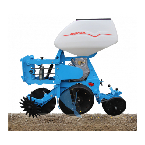
Cette mise en terre assure les meilleurs résultats dans la plupart des conditions.
MONTAGE
Les éléments étant livrés complets avec leur équipement en place, il suffit simplement de les brider
sur la barre porte-outils.
RÉGLAGES DIVERS
➀
Levier de réglage principal du terrage : chaque trou correspond à une variation de profondeur de
1 cm environ.
➁
Réglage intermédiaire du terrage : obtenu en positionnant la goupille rouge dans son cran opposé,
c’est-à-dire en tournant d’1/2 tour le levier
➀
. On obtient ainsi une variation de 5 mm seulement.
➂
Réglage de la pression au sol des roues arrière : par ce réglage on assure un bon équilibre entre
l’appui des roues avant et arrière en fonction des terrains.
➃
Réglage de l’écartement des roues tasseuses.
➄
Chaînette permettant d’escamoter la roulette intermédiaire si besoin lorsque les conditions sont
humides.
➅
Réglage en hauteur du chasse-mottes qui ne doit pas creuser un sillon mais simplement écarter
superficiellement mottes et cailloux.
➆
Taquet d’accrochage en position relevée. En cours de travail laisser le ressort sous sa butée pour
éviter des accrochages involontaires.
➇
Trappe de vidange de graines : rabattre le soc auparavant.
➈
Débrayage individuel : pousser à fond le volant pour comprimer le ressort puis tourner d’1/4 de
tour pour le maintenir en arrière.
IMPORTANT :
avant mise en route vérifier le bon montage de la chaîne (fig. 20), la
souplesse des tendeurs, la rotation des galets, l’absence de points durs en tournant les roues du
châssis. (Graisser les moyeux des rotoherses).
OPTION
Fig. 21 : 11 Mise en terre balancier avec bielle agissant à la fois sur les roues, avant et arrière.
Cet équipement s’adapte directement sur les éléments standards après avoir supprimé le levier
➀
.
12 Rotoherses réglables en hauteur par vis.
Fig. 22 : Bloc arrière à roue concave fonte au lieu du bloc à roues inclinées (sans herse).
Fig. 23 : Bandage souple autonettoyant pour roue concave fonte.
Fig. 24 : Roulette intermédiaire à bandage caoutchouc autonettoyant (modèle large ou étroit).
Fig. 25 : Rasette latérale pour améliorer la fermeture du sillon avant tassage.
Fig. 26 : Double disques avant avec roues accolées pour semis sur préparation réduite, avec ressorts
de pression réglables.
SÄELEMENT
STANDARDAUSRÜSTUNG (fig. 18)
Klutenräumer – selbsteinigende vordere Andruckrolle – abgerundetes Schar – mittlere Andruckrolle
mit Nirostastahlreifen – bewegliche selbstreinigende Schrägandruckrollen. Diese Säelemente arbeiten
in allen Fällen optimal.
MONTAGE
Das Säelement ist so weit montiert, daß es nur noch in den Rahmen eingeschraubt werden muß.
VERSCHEIDENE EINSTELLUNGEN
➀
Tiefenkontrollhebel : jedes Loch, das Sie mit dem Hebel verstellen, bewirkt eine Tiefenablage um
jeweils 1 cm.
➁
Feineinstellung : Durch Drehen des Einstellhebels um eine 1/2 Umdrehung kann die Tiefe um 1/2
cm verstellt werden. Achten Sie auf den roten Spannstift der als Markierung dient.
➂
Bodendruckeinstellung der hinteren Andruckrollen : diese Einstellung gewährt eine gute Balance
zwischen vorderen und hinteren Andruckrollen mit einer optimalen Bodenanpassung.
➃
Einstellung des Abstandes zwischen den hinteren Andruckrollen.
➄
Ketten zum Hochheben der mittleren Andruckrolle-) wird gebraucht bei nassen Bedingungen.
➅
Klutenräumer so hoch einstellen, daß er keine tiefe Rinne zieht, sondern nur die Erdklumpen und
Steine beiseite räumt.
➆
Betätigen Sie die Verriegelung um das Säelement in Transportsellung zubringen. Während der
Arbeit muß die Verriegelung eingerastet sein, damit das Element nicht von selbst in
Transportstellung gebracht wird.
➇
Zur Entleerung des Saatgutbehälters klappen Sie das Schar nach unten.
➈
Einzelabschaltung der Elemente : Drüken Sie die Schaltklaue nach der Seite bis zum Anschlag,
mit einer 1/4 Umdrehung ist die Klaue verriegelt und der Antrieb ist unterbochen !
WICHTIG :
Vor dem Start prüfen Sie die Ketten (fig. 20) im Leerlauf und zusätzlich die
Kettenspanner auf Blockierung (Prüfung bei drehenden Antriebsrädern).
(Schmieren Sie die Krümler !).
ZUSATZAUSRÜSTUNG
Fig. 21 : 11 Tandemführung mit vorderen und hinteren Andruckrollen Diese Sonderausrüstung kann
direkt an die Standardausführung montiert werden, wenn Sie den Hebel
➀
abschrauben.
12 Höhenregulierung der Krümler mit einer Schraube.
Fig. 22 : Hintere Konkavandruckrolle aus Eisen anstatt Schrägandruckrolle.
Fig. 23 : Selbstreinigender Farmflexreifen anstatt Konkavandruck-rollen aus Eisen.
Fig. 24 : mittlere Farmflexandruckrolle (enge u. breite Typen).
Fig. 25 : seitliche Zustreicher zum Schließen der Saatfurche.
Fig. 26 : Kolterscheiben werden anstelle der vorderen Andruckrolle montiert für Minimal-
bodenbearbeitung mit verstellbarer Feder.
АЮАЯ Я
ААО ООУОА (рис. 18)
омьеотвод – передние самоочищающиеся колесо – килевидный сошник – промежуточное стальное
прикатывающее колесо – заделывающие самоочищающиеся V-образные колеса – подставка.
ысевающая секция обеспечивает отличный результат при различных условиях.
ОА
ысевающие секции поставляются в сборе с различными элементами, их необходимо только присоединить к раме.
А УОО А
➀
Основной рычаг (1) изменения глубины: каждое отверстие соответствует изменению глубины приблизительно
на 1 см.
➁
ромежуточное изменение глубины: достигается за счет расположения красного штыря в противоположном
пазу – глубина посева изменяется приблизительно на 5 мм за счет поворота рычага
➀
на пол оборота.
➂
егулировка давления на землю задних колес: посредством данной регулировки достигается надлежащий
баланс давления между передними и задними колесами в соответствии с типом почвы.
➃
егулировка расстояния между заделывающими колесами (несколько отверстий на оси).
➄
епь для зацепки промежуточного прикатывающего колеса, используется по необходимости в условиях
повышенной влажности.
➅
егулировка высоты комьеотвода – комьеотвод не должен создавать борозду, а просто сдвигать в сторону
комки и камни.
➆
локировочный замок для фиксации секции в поднятом положении. ри работе обязательно стопорите
пружину во избежание его случайного захвата.
➇
юк для опорожнения бункера для семян: сначала опустите сошник.
➈
азовое отключение секции: сильно надавите на ручку, опуская пружину вниз, и поверните на _ оборота для
удержания в заднем положении.
АО:
еред вводом в эксплуатацию проверьте сборку цепи (рис. 20), ролики натяжителя, вращение
подшипников, отсутствие блокировок (проверяется посредством поворота опорных колес сеялки). (мазывайте
ступицы).
ООЬ УОА
рис. 21 : 11 алансировочный механизм, действующий на передние и задние колеса. анное оборудование может
быть установлено непосредственно на стандартных секциях после снятия рычага
➀
.
12 егулировка высоты роторов рыхлителей осуществляется при помощи болта.
рис. 22 : аднее, стальное колесо с вогнутым профилем вместо V-образных колес.
рис. 23 : ибкие самоочищающиеся покрышки для вогнутых стальных колес.
рис. 24 : ромежуточные прикатывающие колеса с самоочищающимися покрышками (широкая и узкая модель).
рис. 25 : оковые загортачи для улучшения закрытия борозд до уплотнения.
рис. 26 : ередний двойной диск с боковыми колесами для работы по минимальной (поверхностной) обработке
почвы с регулируемыми пружинами давления.
METERING UNIT
STANDARD EQUIPMENT (fig. 18)
Clod remover – Front self-cleaning wheel – Rounded shoe – Intermediate steel press wheel – Floating
self-cleaning V-wheels – Stand.
This metering unit ensures excellent results in the majority of conditions.
ASSEMBLY
The metering units are delivered with the various elements already mounted, it has just to be clamped
to the tool bar.
VARIOUS ADJUSTMENTS
➀
Main depth control lever : each hole corresponds to a depth variation of around 1 cm.
➁
Intermediate depth control : obtained by positioning the red pin its opposite notch – by giving the
lever
➀
a half turn, a 5 mm variation is thus obtained.
➂
Adjustment of the pressure on the ground of the rear wheels : with this adjustment a good balance
is ensured between the front and rear wheels according to the soils.
➃
Adjustment of the space between the press wheels.
➄
Chain to hook up the intermediate press wheel if need be in wet conditions.
➅
Clod remover height adjustment - the clod remover should not plough a furrow but simply
superficially shift aside the clods and stones.
➆
Locking pawl to lock the planter unit in raised position. When working, leave the spring under the
stop to avoid it getting accidentally caught up.
➇
Trap door for emptying seed hopper : swing back the shoe first.
➈
Individual disengaging : push down hard on the handle, pressing down the spring and give a 1/4
turn to hold it to the rear.
IMPORTANT :
Before starting up, check the chain assembly (fig. 20), the idlers, check that
the rollers rotate and that there are no blockages (check this by turning the planter frame wheels).
(Lubricate the crumbler hubs).
OPTIONS
Fig. 21 : 11 Floating method of planting, acting on front and rear wheels. This equipment can be
directly mounted on the standard units after having removed the lever
➀
.
12 Adjustment to the height of the crumblers by screw.
Fig. 22 : Rear unit with concave steel wheel instead of V-wheels.
Fig. 23 : Supple self-cleaning tyre for concave steel wheel.
Fig. 24 : Intermediate press wheel with self-cleaning tyre (wide or narrow models).
Fig. 25 : Side scrapers to improve furrow closing before firming.
Fig. 26 : Front double disc with side wheels for low till planting, with adjustable pressure springs.
167
UTILISATION
Le boîtier est positionné sur l’élément par les 3 points de fixation
➀
.
Pour retirer le disque de distribution
➁
lorsque le boîtier est en place, il sera nécessaire auparavant
de rabattre la tôle protectrice
➂
, desserrer le boulon
➃
descendre le soc et enlever la vis
➄
.
Deux disques sont livrés de série avec chaque élément semeur :
• LE DISQUE STANDARD 5,5 A5 convient dans la plupart des cas. Il sera à retenir d’office pour tous
les calibres d’enrobées, normalisés entre 3,5 et 4,75 mm, dont les graines, convenablement
sphériques, d’une grosseur toujours inférieure à 4,75 mm, sont dans leur majorité d’un diamètre
moyen compris entre 3,75 et 4,5 mm.
• LE DISQUE 5,7 A5, à alvéoles plus grands, sera par contre à préférer dans les quelques cas
particuliers où les lots de semences, bien que référencés 3,5 – 4,75 mm sont majoritairement
composés de graines d’une grosseur moyenne anormale comprise entre 4,25 et 5 mm. (Attention : si
ces lots comportent des graines dépassant 5 mm ne pas les utiliser avec les disques livrés de série).
Avec le MECA 3, il est également possible de distribuer des graines enrobées d'endives, de chicorée et
légumières calibrées 2,75 - 3,25 mm en utilisant un disque approprié 5 - 10 ou 15 alvéoles.
Important :
• S'assurer, en semis réel, de la bonne distribution et de la bonne densité non seulement à la
mise en route mais aussi pendant la campagne.
• Se méfier et éliminer les lots de semences enrobées comportant de nombreuses graines plates
difformes et hors normes car elles perturbent l'alimentation et provoquent des manques, des
doubles et des casses.
• Toutes les 10 - 15 h, il est souhaitable de vérifier l'état des distributions et des brosses
➅➅
.
Avec ce boîtier, les graines sont pratiquement distribuées jusqu'à la dernière, c'est-à-dire que
très peu de semence est nécessaire pour assurer l'alimentation du disque.
EINSTELLUNG DER SÄMASCHINE
Das Sägehäuse wird an drei Punkten auf dem Element befestigt
➀
.
Wechseln der Säscheiben bei montiertem Sägehäuse
➁
: drücken Sie das Schutzblech zur Seite
➂
,
schrauben Sie die Bolzen
➃
auf drücken Sie da Schar nieder und nehmen Sie die Schraube
➄
heraus.
Zwei Scheiden werden serienmäßig für jedes Element mitgeliefert :
• Standardscheibe 5,5 A5 genügt in den meisten Fällen.
Bei pilliertem Saatgut zwischen 3,5 und 4,75 mm und bei rundem Samen unter 4,75 mm, bei dem die
Mehrzahl der Körner zwischen 3,75 und 4,5 mm liegt sollte diese Scheibe benutzt werden.
• Säscheibe 5,7 A5 mit größeren Löchern : benutzen Sie die Scheibe bei Samengrößen 3,5 - 4,75 mm,
wenn die Mehrheit des Samens zwischen 4,25 und 5 mm liegt (Wichtig : sollte der Samen größer wie
5 mm sein, benutzen Sie nicht die mitgelieferten Schneiben).
Mit dem MECA 3 kann man Endivien, Chiccoree und Gemüsesamen in den Samengrößen 2,75 -
3,25 mm ausbringen, wenn Sie Säscheiben mit 5,10 oder 15 Löchern benutzen.
Wichtig :
• Überprüfen Sie das Sägerät nicht nur am Beginn der Aussaat, sondern auch öfters während
der laufenden Saison.
• Achten Sie auf einwandfreies Saatgut. Bei Nichtbeachtung kann eine schlechte Befüllung der
Säscheibe, schlechte Ablage, Doppelbelegung und gebrochenes Saatgut auftreten.
• Überprüfen Sie die Säscheiben und Bürsten alle 10 -15 Stunden
➅➅
.
Mit diesem Sägehäuse wird eine Aussaat fast bis zum letzten Samenkorn gesichert. Sie
brauchen nur eine sehr geringe Saatgutmenge um die Befüllung der Säscheibe zu
gewährleisten.
УООА
орпус дозатора крепится на секции в трех местах
➀
.
ля снятия высевающего диска
➁
при установленной корпусе дозатора отодвиньте защитную пластину
➂
,
открутите болт
➃
, опустите сошник и удалите болт
➄
.
ва диска поставляются в комплекте с каждым дозатором:
•АА  5,5 А5 подходит в большинстве случаев. го следует использовать для посева
дражированных семян обычных размеров 3,5-4,75 мм и семян, имеющих сферическую форму, размерами до 4,75
мм, средним диаметром для большинства семян находится между 3,5 и 4,75 мм.
• 5,7 А5 с бóльшими ячейками следует применять в особых случаях при использовании партий семян,
размеры которых рассматриваются как 3,5-4,75 мм, однако имеют в своем составе большое количество семян
размерами 4,25-5 мм. (ажно: если в партии семян попадаются семена размерами свыше 5 мм, не пользуйтесь
поставленными дисками).
 помощью А 3 можно дозировать дражированный эндивий, цикорий и семена овощей размерами 2,75-3,25 мм,
используя соответствующие диски на 5, 10 или 15 ячеек.
ажно:
•роверяйте высевание и семена не только при вводе в эксплуатацию, но и время от времени в течение
сезона.
•удьте бдительны при использовании партий дражированных семян, содержащих деформированные или
нестандартные семена, наносящие ущерб системе подачи и служащие причиной пропусков, двойного
посева или крошения семян.
•роверяйте посевные диски и щетки
➅➅
каждые 10-15 рабочих часов.
спользуя данный корпус дозатора, семена высеваются вплоть до последнего семени, а это означает, что
для наполнения диска необходимо очень малое количество семян.
OPERATION
The metering box is positioned on the unit by 3 fixing points
➀
.
To remove the seed disc
➁
when the metering box is mounted, push aside the protection plate
➂
,
unscrew the bolt
➃
, pull down the shoe and remove the screw
➄
.
Two disc are delivered with each metering unit :
• THE STANDARD DISC 5,5 A5 is suitable in most cases. It should be automatically used when sowing
normalised sizes of pelleted seeds between 3,5 and 4,75 mm and when the seeds are spherical and
under 4,75 and have for majority an average diameter between 3,75 and 4,5 mm.
• THE DISC 5,7 A5, with bigger cells, will however be used in certain specific cases when using batches
of seeds which although referenced 3,5 - 4,75 mm have a majority of abnormal sizes between 4,25
and 5 mm. (Important : should these batches have seeds over 5 mm do not use them with the
delivered discs).
With the MECA 3, it is possible to meter pelleted French endive, chicory and vegetable seeds of sizes
2,75 - 3,25 mm using appropriate 5 - 10 or 15 cell discs.
Important :
• Check the distribution and seed population not only when starting up but also from time to
time during the season.
• Be careful when using batches of pelleted seeds which contain misshapen or non standard
sized seeds which interfere with the feed system and cause misses, doubles or broken seeds.
• Check the seed discs and the brushes
➅➅
every 10 - 15 hours.
With this metering box, the seeds are metered out to almost the last seed which means very little
seed is needed to ensure the disc feed.
1
1
5
1
Fig.
ис.
28 Fig.
ис.
29
5
2
3
6
1
1
1
4
BOITIER DE DISTRIBUTION – METERING UNIT – SAATGUTBEHÄLTER MIT SÄSCHEIBE UND SCHAR –ОАО
PIÈCES DE
RECHANGE
SPARE
PARTS
ERSATZEILE
аталог
запасных частей
MECA 3
MECA 3 avec fertiliseur et Microsem insecticide
CCBCCCBCBABABAAA
6564324*135241321
12 13,514,515 16 16,517 18 18,519 20 20,521 22 23 25
66,
577,
588,
599,
510 10,511 11,512,5
44,
555,
566,
577,
58
La boîte de distance comporte un ensemble supérieur baladeur à 6 dentures et un pignon inférieur fixe à 3 dentures.
Le tableau ci-dessous indique les distances théoriques réalisables pour chaque disque.
Calcul sur la base d'un développé de roue de 1,96 m. Formule de calcul pour un développé de roue différent :
Exemple : Distance = (17 cm x ND) (ND = nouveau développé en m).
1,96
ATTENTION : les distances du tableau sont théoriques, des variations de 5 à 10 % sont possibles sur certains terrains. Des
contrôles de densités en début et pendant la campagne sont indispensables.
Pour changer la distance, pousser le tendeur
➂
, accrocher son taquet
➃
puis placer face à face les dentures retenues. Bloquer la vis
du pignon supérieur puis rabattre le tendeur
➂
. Lubrifier (gas-oil) modérément mais journellement la chaîne.
3
4
Fig.
ис.
30
BOITE DE DISTANCES SEED SPACING GEARBOX WECHSELGETRIEBE
ООА А Я Я АА У А
815
оробка передач точного высева состоит из верхнего 6-звездочного ведомого блока и нижнего 3-звездочного ведущего блока.
 таблице приводятся расстояние между семенами, соответствующее каждому диску: наклейка, находящаяся на сеялке, дает те же значения в полевых условиях.
асчеты сделаны для базовой длины обода колеса 1,96 м. ормула для другой длины обода колеса:
ример: асстояние =17 см ( расстояние между семенами) х ND (ND = новая длина обода колеса в м)
1,96 (длина обода колеса в м)
АО: показатели расстояния, приведенные в таблице, являются приблизительными и могут различаться на 5-10 % в зависимости от типа почвы. роверяйте
расстояние при вводе в эксплуатацию и в течение сезона.
ля изменения расстояния между семенами надавите на рычаг
➂
, зафиксируйте его фиксатором
➃
и подведите необходимую вам звездочку. атяните болт на верхней
звездочке и верните рычаг
➂
) в исходное положение. Умеренно смазывайте механизм, а цепь смазывайте ежедневно.
Der Aussaatabstand wird im Getriebe durch das obere Sechsfachzahnrab und das untere Dreifachzahnrad eingestellt.
Die unten angegebene Saattabelle zeigt die theoretisch realisirbare Distanz für jede Scheibe. Ein Aufkleber auf dem Getriebe zeigt die selben Hinweise.
Berechnung auf Grund des Umfangs eines Rades von 1,96 m. Berechnungsformel für einen anderen Radumfang :
Zun Beispiel : Distanz = 17 cm (= Saamendistanz) x ND (ND = Neuer Umfang))
1,96 (Theoretischer Radumfang in m)
WICHTIG : die Abstände auf der Sätabelle sind theoretisch und je nach Bodenbeschaffenheit um 5 - 10 % verstellbar. Überprüfen Sie die
Abstände vor Arbeitsbeginn und während der Aussaat.
Um den Körnerabstand zu verändern, drücken Sie den Kettenspanner
➂
nach oben und rasten diesen ein
➃
, wählen Sie die richtige
Zahnradkombination. Befestigen Sie das obere Zahnrad mittels einer Stellschraube und bringen Sie den Kettenspanner wieder in die Ausgangs-
stellung
➂
. Schmieren Sie de Kette täglich.
The seed spacing gearbox consists of an uper unit with 6-sprocket sliding cluster and a lower fixed 3-sprocket cluster.
The table indicates the theorical distances possible for each disc. A decal placed on the gearbox will provide the same indications when in the field.
Calculated on the basis of wheel evolute of 1,96 m. Formula for a different wheel evolute :
Example : Distance = 17 cm (= distance between 2 seed) x ND (ND = new evolute in m))
1,96 (wheel evolute in m)
IMPORTANT : the distances given in the table are theoretical and may vary from 5 to 10 % in certain soils. Check the distances when
starting up and also during the season.
To change the seed spacing, push the idler level
➂
, lock its pawl
➃
then align to the proper sprocket combination. Tighten the srew on the
upper sprocket and pull back the idler
➂
, Oil moderately (gas oil) and daily the chain.
DISTANCE DE SEMIS SOWING DISTANCES ABSTÄNDE DER SAMENKÖRNER О АОЯЯ
Nombres d'alvéoles
Number of holes
Anzahl der Zellen
оличество отверстий
123
C
B
A
456
Sélection de la
boîte de distances
Sélection
of gearbox
Einstellungdes
Getriebekastens
ыбор коробки передач
5
10
15
DENSITÉS
DENSITIES
DICHTE DES BESTANDES
орма высева
Distances entre graines sur le rang - Distance between seeds on the rows
Abstands zwischen den Samenkörnern innerhalb der Reihen - асстояния между семенами в рядах
10 11 12 13 14 15 16 17 18 19 20 21 22 23 24 25 26
45 222220 202000 185160 170920 158740 148140 138900 130720 123460 116960 111110 105820 101000 96620 92580 88900 85460
50 200000 181800 166680 153840 142860 133320 125000 117640 111120 105260 100000 95240 90900 86960 83340 80000 76920
56 178530 162300 148770 137200 127400 118800 111380 104800 99000 93780 89270 84850 81150 77470 74380 71270 68600
60 166660 151500 138880 128200 119040 111110 104160 98040 92590 87720 83330 79360 75750 72460 69440 66670 64100
65 153540 139860 128200 118340 109880 102560 96150 90500 85470 80950 76920 73250 69930 66890 64100 61540 59170
Distances entre rangs
Sistance between rows
Abstand zwisvhen den Reihen
асстояние между рядами
VITESSE DE TRAVAIL
3 à 8 km/h suivant l'état du terrain.
Retenir cependant une vitesse
raisonnable comprise entre 4 et 6
km/h : la mise en terre et la régularité
n'en seront que meilleures.
WORKING SPEED
3 to 8 km per hour according to field
conditions. A reasonable speed
between 4 and 6 km.p.h. will ensure
good soil penetration and regular
sowing.
ARBEITSGESCHWINDIGKEIT
3 - 8 Studenkilometer je nach
Bodenbeschaffenheit.
Die Grundgeschwindigkeit zwischen
4 und 6 km sichert eine gute Aussaat,
bei optimalen Bodenverhältnissen.
АОАЯ ООЬ
3-8 км/ч в соответствии с полевыми
условиями. ри работе со скоростью 4-6
км/ч обеспечивается хорошая заделка и
точный высев семян.
* Attention : pour ce rapport, il est nécessaire de décaler la boîte et le 3èpoint de quelques mm. * Attention : for this gear ratio, it is necessary to off - set a few mm the gearbox and the third point linkage.
* Achtung : für diese Drehzahl, man muß das Getriebe und der dritte Punktanbau von einigen mm - versetzen. * нимание: для данного передаточного числа необходимо сдвинуть коробку передач и трехпозиционное
сцепляющее устройство на несколько мм.
INCIDENTS POSSIBLES ET CAUSES
Alvéoles de disques trop petits (voir page 7).
Graines enrobées difformes et hors calibre ne pouvant pénétrer ou bouchant les alvéoles :
vérifier l'état et la position de la brosse.
Corps étranger dans la semence.
Voûtage en fond de trémie à cause de l'humidité (ne pas laisser de graines enrobées
séjourner dans les trémies par temps humide).
Graines enrobées gonflées par l'humidité et bouchant les alvéoles.
Alvéoles encrassés par produit de traitement : mettre du talc dans la semence.
Alvéoles de disques trop grands (d'origine ou par usure).
Usure de l'intérieur des boîtiers à l'aplomb des alvéoles (rainure créée par le glissement des
graines).
Trappes de vidange non étanches ou mal fermées.
Volet en toile plastique réglant le niveau de graines au fond du boîtier absent ou défectueux.
Vitesse de travail excessive (voir page 8).
SOCS USÉS ou bouchés.
Grippage d'un ou plusieurs disques.
Corps étranger dans la semence.
Points durs dans la transmission (chaîne - tendeur - roulements - bloc roue - boîte
distances…).
Roulettes intermédiaires bloquées ou désaxées.
Corps étranger dans le produit.
Produit humide : ATTENTION à L'HUMIDITÉ.
Mauvais remontage du mécanisme.
Bloc goulotte déformé.
Chaînes non alignées ou sautées.
Clips de tube jonction absent.
ENTRETIEN
Pression de gonflement des pneumatiques 1 kg/cm2 (1 bar).
Un graisseur sur le moyeu de chaque bloc roue de châssis demande un graissage 1 fois par campagne
(1).
Les axes de rotoherses nécessitent un graissage journalier, les autres moyeux sont équipés de bagues
autolubrifiantes ou de roulements ne nécessitant aucun graissage.
Huiler sans excès galets, chaînes d'éléments, de blocs roues et de boîtes de distances (huile ou gazoil).
A la mise en route, s'assurer qu'aucun axe ni galet n'est freiné par la peinture.
Vérifier journellement le bon blocage des pièces d'attelage car le desserrage des écrous provoquerait la
rupture des brides.
Après la campagne procéder à un nettoyage complet, surtout des boîtes de distribution, et entreposer le
matériel : A L'ABRI, vérins fermés.
(1) Les moyeux à billes des roues de châssis demandent un certain volume de graisse, en tenir compte lors du 1er
graissage.
NOMBREUX
MANQUES
NOMBREUX
DOUBLES
SEMIS
IRRÉGULIERS
MICROSEM
Débit variable
ou insuffisant
sur 1 seul boîtier
УА АО  ОО

лишком маленькие ячейки дисков (см. стр. 7)
еформированные или некалиброванные дражированные семена не могут
проникнуть или блокируют ячейки: проверьте состояние и положение щетки.
 семенам подмешено постороннее вещество.
липшиеся семена на дне бункера (не оставляйте в бункерах дражированные
семена при повышенной влажности).
лажные семена набухли и забили ячейки.
Ячейки забиты продуктами обработки семян: посыпьте семена тальком.
лишком большие ячейки дисков (изначально или износились).
знос на внутренней стороне дозатора поверх ячеек (паз, появившийся
вследствие скольжения семян).
ыпускные люки закрыты негерметично или неправильно.
ластмассовая заслонка уровня семян отсутствует, неисправна или находится
на дне дозирующей коробки.
овышенная рабочая скорость (см. стр. 8)
О ОЬ или забиты.
локирован один или несколько высевающих дисков.
 семенам подмешено постороннее вещество.
локировка в трансмиссионных устройствах (цепь, шестерни холостого хода,
подшипники, колесное устройство, коробка передач).
ромежуточные прикатывающие колеса блокированы или за границами ряда.
 микрогранулам подмешено постороннее вещество.
лажность в продуктах: А АОО АЯЯ.
еправильная сборка устройства.
ерекосилось устройство выпускного лотка.
лохо натянуты цепи.
Отсутствуют зажимы на соединительной трубке.
О ОУА
авление колес: 1 кг/см2 (1 бар).
аждый сезон смазывайте ступицы ведущих колес (1).
асленки приводных валов следует смазывать ежедневно, другие ступицы оборудованы
самосмазывающимися втулками или подшипниками, не требующими смазки.
Умеренно смазывайте все подшипники, цепи дозатора, цепи ведущих колес и цепь коробки
передач.
ри вводе в эксплуатацию убедитесь, что подшипники и оси не блокированы краской.
жедневно проверяйте затяжку болтов, поскольку раскрутившиеся гайки могут послужить
причиной поломки зажимов.
о окончанию сезона тщательно очистите сеялку, а в особенности высевающие аппараты, и
храните ее с закрытыми цилиндрами в сухом месте, защищенном от попадания грязи.
(1) олесные ступицы блоков ведущих колес требуют особого количества смазки. Это следует принимать во
внимание при первом смазывании.
ОУ Я
 О
ОЬО Я
АЬ
О
MICROSEM
збыточный или
недостаточный
выход на одном
устройстве
FUNKTIONSSTORUNGEN UND GRUNDE
Zellenlöcher zu klein (seihe Seite 7).
Gebrochenes und nichtkalibriertes Saatgut verstopfen die Zellenlöcher : überprüfen Sie den
Zustand und die Position der Bürste. Fremdmaterial vermischt mit dem Saatgut.
Feuchtes Saatgut unten im Saatkasten (lassen Sie kein Saatgut bei feuchtem Wetter im
Saatkasten).
Feuchtes Saatgut quillt durch Nässe und verstopft die Zellenlöcher.
Zellenlöcher verstopfen bei gebeiztem Saatgut : geben Sie Talkum zum Saatgut.
Zellenlöcher zu groß (falsche Scheibenwahl oder durch Verschleiß).
Verschleiß auf der Innenseite der Säscheibe bei den Zellenlöchern (Zellenloch vergrößert sich
durch Abnutzung).
Entleerungsklappe nicht wasserdicht oder nicht korrekt geschlossen.
Befüllbegrenzer aus Plastik fehlt, ist bechädig oder liegt auf dem Boden des Sägehäuses.
Überhöhte Arbeitsgeschwindigkeit (siehe Seite 8).
Schare verschliessen oder verstopft.
Eines oder mehrere Scheiben blockieren.
Fremdkörper im Saatgut.
Blockierung der Antriebselemente (Kette - Ketten spanner - Lager - Antriebsräder - Getriebe).
Zwischenandruckrollen blockieren oder sind nicht in der Spur.
Fremdköper im Streugut.
Feuchtigkeit im Streugut : Vermeiden Sie Nässe und Verschmutzung.
Dieses Streugut kann nicht verwendet werden.
Auslaufleiblech verbogen
Schlecht gefluchtete Ketten.
WARTUNG
Reifendruck : 1 kg/cm2 (1 bar).
Besonders die Scheibenkrümler müssen täglish geschmiert werden, während alle Lagers-tellen
selbstschmierend sind und nicht geschmiert werden brauchen.
Mit öl werden Spannrollen, Achsen, Elementketten, Antriebsketten und Getriebeketten mäßig geschmiert.
Bei Arbeitsbeginn üverprüfen Sie die Spannrollen und die Achsen, ob sie nicht mit Farbe verklebt sind.
Uberprüfen Sie täglich Schrauben des Dreipunktgestänges, da eine verlorene Mutter zum Bruch der
Befestigungsklammer führen kann.
Am Ende der Saison reinigen Sie die Maschine gründlich, besonders die Sägehäuse und lagern Sie die
Maschine mit eingezogenen Hydralikzylindern an einem trockenen und staubfreiem Platz.
GROBE MÄNGEL
STARKE DOPPEL-
BELEGUNG
UNREGELMÄßIGE
ABLAGE
MICROSEM
verschiedene oder
mangelhafte
Ausbringung
TROUBLE SHOOTING AND CAUSES
Disc cells too small (see page 7).
Misshapen or non-calibrated pelleted seeds cannot penetrate or are blocking the cells : check
the condition and position of the brush.
Foreign material mixed with the seeds.
Damp seeds at the bottom of the hopper (do not leave pelleted seeds in hoppers in damp
weather).
Damp seeds swollen with moisture and clogging the cells.
Cells clogged with seed treatment product : put some talc throught the seeds.
Discs cells too large (originally or though wear).
Wear on the inside of the metering boxes above the cells (groove made by seeds slipping).
Emptying trap doors are not watertight or are not correctly closed.
Plastic shutter for the seed level missing, faulty or at the bottom of the metering box.
Excessive working speeds (see page 8).
SHOES WORN or clogged.
One or several discs blocking.
Foreign material mixed with seeds.
Blockage in transmission units (chain - idler - bearings - wheel unit - gearbox).
Intermediate press wheels blocked or out of line.
Foreign material mixed with product.
Moisture in product : AVOID MOISTURE CONTAMINATION.
Improper assembly of unit.
Outlet chute unit warped.
Badly aligned chains.
Clips on junction tube missing.
MAINTENANCE
Tyre pressure : 1 kg/cm2 (1bar), (15 p.s.i.).
Greasing on the hub of each drive wheel block requires greasing once per season (1).
The crumbler shafts need daily lubrication, others hubs are equipped with self lubricating bushings or
bearings which require no lubrication.
Oil moderately rollers, shafts, metering unit chains, drive wheel unit chains and gearbox chain (oil or gas
oil).
When starting up, chack that the rollers and shafts are not blocked by paint.
Check daily the correct tightening of hitch parts, as loose nuts could cause breaking of clamps.
At the end of the season, clean the machine thoroughly, especially the metering boxes and store the
machine with cylinders closed in a dry dust-free place.
(1) The wheel hubs of the drive wheel blocks require a specific amount of grease. This should be taken into consideration
at the first lubrication.
EXCESSIVE
SKIPPING
EXCESSIVE
DOUBLING
IRREGULAR
SOWING
MICROSEM
Variable
or insufficient
output on 1 unit
149
Distances de semis entre rangs (en cm et inches)
Sowing distances between rows (in cm and inches)
Abstände der Reihen (cm und inches)
осевное расстояние между рядами, (в см или в дюймах)
HECTARES А ACRES А
30 40 45 50 55 60 65 70 75 80 20 30
cm cm cm cm cm cm cm cm cm cm inch. inch.
4
4250 3190 2835 2550 2320 2125 1960 1820 1700 1595 1015 680
5
3400 2550 2265 2040 1855 1700 1570 1455 1360 1275 815 540
6
2835 2125 1890 1700 1545 1415 1310 1215 1135 1060 675 450
8
2125 1595 1415 1275 1160 1060 980 910 850 795 510 340
10
1700 1275 1135 1020 925 850 785 730 680 635 405 270
11
1545 1160 1030 925 845 775 715 660 620 580 370 250
12
1415 1060 945 850 775 710 655 605 565 530 335 225
4
4100 3080 2735 2465 2240 2050 1895 1760 1640 1540 980 655
5
3285 2465 2190 1970 1790 1640 1515 1405 1315 1230 785 525
6
2735 2055 1825 1640 1495 1370 1265 1175 1095 1025 655 435
8
2050 1540 1370 1230 1120 1025 945 880 820 770 490 325
10
1640 1230 1095 985 895 820 760 705 655 615 390 260
11
1490 1120 995 895 815 745 690 640 595 560 355 240
12
1370 1025 910 820 745 685 630 585 545 515 325 220
Nombre de rangs du semoir
Number of rows of planter
Anzahl der Reihen der Sämaschine
оличество рядов сеялки
COMPTEUR D’HECTARES
ET DE VITESSE
Montage du capteur suivant fig. ci-dessous.
Le plus près possible d’un palier.
Mise en route : se reporter à la notice jointe
avec chaque compteur.
RESUME : 1 impulsion sur la touche ;
MODE > Ui = vitesse d’avancement
MODE > S = surface
MODE > St = surface totale
Programmation : sur MODE S ou St.
MODE > S, 1 seconde sur PROG > Ci,
avec les touches + , – , entrer 1,96 (m)
(circonférence de la roue)*
MODE > S, 1 seconde sur PROG > Ci,
1 seconde sur PROG > LA ;
LA = largeur de travail avec les touches + , – ,
entrer la largeur de travail.
Exemple : 4 rangs à 0,80 m = 3,20
6 rangs à 0,75 m = 4,50
Retour automatique en S après 5 secondes
* Nota : il n’est pas tenu compte du patinage
possible sur certains terrains.
Code confidentiel : voir notice. Remise à “0”
surface : S ou St 3 secondes sur RAZ .
HECTARE COUNTER
SPEED COUNTER
Sensor assembly, according to schema, as
close as possible to a bearing.
Start up : see manual enclosed with each
counter.
SUMMARY : press down once ;
MODE > Ui = forward speed
MODE > S = surface
MODE > St = total surface
Programming : MODE S or St.
MODE > S, 1 second on PROG > Ci,
with keys + , – , enter 1,96 (m)
(circumference of wheel)*
MODE > S, 1 second on PROG > Ci, 1
second on PROG > LA ;
LA = working width.
with the keys + , – , enter the working
width.
Example : 4 rows at 0,80 m = 3,20
6 rows at 0,75 m = 4,50
Return automatically to S after 5 seconds.
* Nota : Possible slipping on certain soils is
not taken into account.
Secret code : see manual.
Surface reset : S or St ; 3 seconds on RAZ .
HEKTARZÄHLER
GESCHWINDIGKEITSANZEIGE
Sensor muß passend zum Programm, so
nahe wie möglich am Lager montiert werden.
Start : Betriebsanleitung liegt jedem
Hektarzähler bei.
PROGRAMM : Drücken Sie
MODE > Ui = Vorwärtsgeschwindigkeit
MODE > S = Fläche
MODE > St = Gesamtfläche
Programmierung : MODE S oder St.
MODE > S, drücken Sie 1 Sekunde auf PROG > Ci,
mit Schlüssel
+ , – ,
geben Sie 1,96 (m)
ein (Radumfang)*
MODE > S, drücken Sie 1 Sekunde auf PROG > Ci,
1 Sekunde auf PROG > LA ;
LA = Arbeitsbreite mit den Schlüsseln
+ , –
,
drücken Sie arbeitsbreite.
Beispiel : 4 Reihen mit 0,80 m = 3,20
6 Reihen mit 0,75 m = 4,50
Autom. Rückstellung auf S nach 5 Sekunden.
* Anmerkung : Möglicher Schlupf auf unter-
schiedlichen Böden ist nicht berücksichtigt.
Geheimcode : Siehe Bedienungsanleitung.
Rückstellung der Flächenanzeige : S oder St
3 Sekunden auf
RAZ .
ЭО 
АО  ОО
огласно схеме установите датчик как можно
ближе к креплению.
вод в эксплуатацию: см. руководство,
прилагаемое к каждому счетчику.
ОАОА: один раз нажмите
MODE -> Ui = скорость вперед
MODE -> S = площадь
MODE -> St = общая площадь
рограммирование: MODE S или St.
MODE -> S удерживайте кнопку PROG -> Ci в
течение 1 с, кнопками + или – введите значение
1,96 (м) (длина окружности колеса)*.
MODE -> S, удерживайте кнопку PROG ->
Ci в течение 1 с и в течение 1 с кнопку PROG
-> LA;
LA = рабочая ширина.
нопками + или – введите значение рабочей
ширины.
апример, 4 ряда по 0,80 м = 3,20
6 рядов по 0,75 м = 4,50
озврат к S автоматически через 5 секунд.
* римечание: возможное скольжение на
различных типах почвы не учитывается.
екретный код: см. руководство. брос индикации
площади: удерживайте RAZ в течение 3 секунд.
COMPTEUR D’HECTARES
MECANIQUE
Montage suivant fig. ci-dessous, si possible près d’un
palier supportant l’axe hexagonal. Le levier de
commande étant
préréglé en usine, son orientation ne doit pas être
modifiée.
Montage terminé, faire tourner, lentement l’axe
hexagonal afin de s’assurer qu’au point haut de la
came le levier conserve encore une marge
d’oscillation.
La surface ensemencée sera obtenue en divisant le
chiffre relevé sur le compteur par le chiffre du tableau
ci-dessous correspondant aux caractéristiques du
semoir.
Exemple : pour un semoir 4 rangs à 80 cm, le tableau
indique 1595, si le compteur marque 16360, la surface
sera 16360/1595 = 10,25 ha.
ATTENTION : il n’est pas tenu compte ici d’un léger
patinage des roues possible dans certains terrains.
MECHANICAL HECTARE (ACRE)
COUNTER
Mounted on toolbar as per above illustration.
The metering unit control lever having been
preset in the factory, its direction should not
be altered.
After the equipment has been mounted,
rotate the hexagonal shaft slowly to ensure
that when the cam reaches its highest point
the lever still has space for oscillation.
The planted surface is obtained by dividing
the figure recorded on the counter by the
figure given in the table below which
corresponds to the planter characteristics.
MECHANIKER
MEKTARZÄHLER
Montage auf die Geräte Trägerstange nach
nebenstehender Abbildung.
Die Einstellung des Zähler Bedienungshebel
wurde im Werk vorgenommen. Die
Orientierung darf also nicht verändert werden.
Nach beendeter Montage, ist die
sechskantige Achse leicht zu drehen, um
festzustellen, ob der Hebel am oberen
Nockenpunkt noch genug Schwingraum hat.
z.B. : Bei einer 4-reihigen Sämaschine 80 cm
gibt die Tafel 1595 an, wenn der Hektarzähler
16360 zeigt. Die ausgesäte Oberfläche ist
daher 16360 : 1595 = 10.25 ha.
А  АО
(АО)
Установлен на раме как показано на рисунке.
онтрольный рычаг дозирующего агрегата был
предварительно настроен на заводе, его
направление вращения не должно меняться.
осле установки оборудования медленно
покрутите шестигранный вал для проверки,
чтобы, когда кулачок достигает наивысшей
точки, у рычага имелось пространство для
колебаний.
начение засеянной площади достигается за счет
деления значения, зарегистрированного
счетчиком, на значение в нижеприведенной
таблице, соответствующее характеристикам
сеялки.
Fig.
ис.
33
CHARIOT DE TRANSPORT
Position transport
• Le semoir est attelé au tracteur avec le relevage en position haute (attelage 3
points fig. 53).
• Positionner les 2 blocs roues en position route et les verrouiller avec la broche
➂fig. 52.
• Positionner les 2 roues avec leurs moyeux dans les fourreaux (tubes carrés)
des blocs roues et verrouiller avec les broches ➁fig. 49.
• Bloquer la béquille en position basse (voir fig. 48).
• Dételer le semoir du tracteur.
• Déverrouiller la flèche (A) fig. 50 du chariot en enlevant l'axe ➀du bridage (C)
de la flèche (voir fig. 51).
• Atteler le tracteur à la flèche (A) fig. 50 du chariot de transport.
• Bloquer la béquille en position haute.
• Positionner les plaques d'éclairage (B) fig. 49 dans leurs fourreaux.
• Brancher la prise d'alimentation du système d'éclairage au tracteur (voir notice
Kit d'éclairage).
ATTENTION :
• Ne pas se positionner sous la charge.
• Les éléments ne doivent pas toucher le sol.
• Verrouiller les rayonneurs avec les broches en position transport.
• Vitesse Maxi sur la route 25 km/h.
Position travail
Faire les opérations inverses à celles décrites ci-dessus.
Entretien
Pression de gonflement des pneumatiques 4,2 bar.
Un graisseur sur l'axe d'articulation de la flèche demande un graissage 1 fois par
campagne.
Avant semis, vérification et mise en place de tous les carters de protection.
Pour toutes autres préconisations, se reporter à la page 15.
TRANPORTKARREN
Transportposition
• Die Sämaschine wird am Traktor mit dem Hubarm in erhöhter Position
angekuppelt (3-punkt-Kupplung Abb. 53).
• Die 2 Radblöcke in Straßenposition bringen und sie mit der Spindel ➂Abb. 52
verriegeln.
• Die beiden Räder mit ihren Naben in die Hülsen (viereckige Röhren) der
Radblöcke setzen und mit den Spindeln verriegeln ➁Abb. 49.
• Die Deichselstütze in niedriger Position blockieren (siehe Abb. 48).
• Die Sämaschine vom Traktor abkuppeln.
• Den Baum (A) Abb. 50 des Transportskarrens entriegeln, indem Sie die Achse
➀der Einspannung (C) des Baums abnehmen (siehe Abb. 51).
• Den Traktor am Baum (A) Abb. 50 des Transportkarrens ankoppeln.
• Die Deichselstütze in hoher Position blockieren.
• Die Beleuchtungssätze (B) Abb. 49 in ihren Hülsen positionieren.
• Die Steckdose des Beleuchtungssystems an den Traktor anschließen (siehe
Gebrauchsanweisung des Beleuchtungssets).
ACHTUNG :
• Sich nicht unter die Last stellen.
• Die Elemente dürfen den Boden nicht berühren
• Die Spuranzeiger mit den Spindeln in Transportposition verriegeln.
• Höchstgeschwindigkeit auf der Staße 25 km/h.
Arbeitsposition
Die oben beschriebenen Vorgänge rückwärts ausführen.
Wartung
Reifendruck 4,2 bar.
Ein Öler auf der Gelenkachse des Baums braucht eine Ölung pro
Aussaatkampagne.
Vor dem Säen sämtlice Schutzgehäuse überprüfen und anbringen.
Für alle anderen Empfehlungen siehe Seite 15.
АОО ОО
озиция для транспортировки
•  рабочем положении сеялка соединяется с трактором посредством 3-х точечного
навесного устройства (рис.53).
• ля транспортировки по дорогам двухколесная тележка стопорится пальцем
➂
(рис. 52).
• озиция 2-х колесной тележки стопорится пальцем
➁
(рис.49) в квадратной балке.
• Опустите сеялку как показано на рис. 48.
• Отсоедините сеялку от трактора.
• азблокируйте шарнирную раму (А) рис.50 для транспортировки поднимите палец
() и освободите шарнирную раму (см. рис.51).
• одсоедините трактор к транспортному приспособлению через шарнирную раму (А)
рис. 50.
• однимите сеялку навеской трактора.
• а транспортном приспособлении установлены светоотражательные пластины ()
рис.49.
• одсоедините световую сигнализацию к розетке трактора (см. инструкцию световой
сигнализации).
А :
•е стойте под грузом.
•ысевающие секции не должны касаться земли.
•однимите рядные маркеры и зафиксируйте из в позиции для
транспортировки.
•аксимальная скорость передвижения: 25 км/ч.
абочая позиция
ыполните вышеописанную процедуру в обратном порядке.
Обслуживание
авление в колесах: 4,2 атм.
асленку на шарнирной раме смазывайте раз в сезон.
роверьте и установите все защитные элементы.
Обращайтесь к странице 15 по всем остальным рекомендациям.
TRANSPORT CARRIAGE
Transport position
• The planter is coupled to the tractor with the lift arm in upper position (3 point
coupling fig. 53).
• Position the 2 wheel units in the road position and lock them with the pin ➂
fig. 52.
• Position the 2 wheels with their hubs in the wheel units'sleeves (square tubes)
and lock with pins ➁fig. 49.
• Lock the stand in lower position (see fig. 48).
• Uncouple the planter from the tractor.
• Unlock the drawbar (A) fig. 50 from the transport carriage by lifting the pin (C)
from drawbar lock (see fig. 51).
• Couple the tractor to the transport carriage drawbar (A) fig. 50.
• Lock stand in upper position.
• Position lighting plates (B) fig. 49 in their sleeves.
• Connect lighting system power plug to the tractor (see Lighting Kit instructions).
WARNING :
• Do not place your body under the load.
• The elements must not touch the ground.
• Lock row markers with the pins in the transport position.
• Maximum road speed : 25 km/h.
Working position
Carry out procedure described above in reverse order.
Maintenance
Tyre pressure : 4,2 bar.
A lubricator on the drawbar kingpin requires greasing once a season.
Before sowing, check and install all protective housings.
Refer to page 15 for all other recommendations.
500 x 156,5 x 80 x 15
5 mm
MICROSEM
1013
Montage et disposition générale suivant photos ci-dessus et dessins de la page 1.
Montage des descentes côtés droit et gauche suivant fig. 36-37.
Les tuyaux seront à ajuster à leur plus courte longueur afin d'éviter les coudes :
ceci étant à faire semoir ATTELÉ et RELEVÉ.
Réglage du débit (fig. 38)
Le débit se règle à partir des pignons doubles
➀
et interchangeables
➁
. Un décalque
collé au support facilite ce réglage. Les renseignements fournis n'étant qu'indicatifs, un
contrôle à la mise en route reste indispensable.
Cet appareil craint l'humidité. Il ne doit être utilisé qu'avec des microgranulés et non
avec des poudres ou des granulés.
Le boîtier 2 rangs se transforme en 1 rang en remplaçant la goulotte 2 sorties par une
goulotte 1 sortie et en plaçant un cache intérieur.
Assembly according to above figures and drawings on page 1.
Hose assembly right and left following fig. 36-37.
The hoses should be as short as possible to avoid bends : this would be done with the
planter HOOKED UP and LIFTED.
Output adjustment (fig. 38).
The output can be adjusted using the double sprockets
➀
and the interchangeable
sprockets
➁
. A decal on the bracket will help with this adjustment. The information
provided is only to give an indication, always check when starting up.
Avoid moisture contamination. The unit must only be used with microgranular products
(no powders or granular products).
The 2-row metering box can be changed into a 1-row box by replacing the double outlet
with a single outlet and installing a shield in the inside.
Die erste Seite beinhaltet Figuren und Zeichnungen als Montagebeispiele.
Schlauchmontage rechts und links sehen Sie in Figur 36-37.
Die Schläuche sollten so kurz wie möglich montiert werden, um ein Abknicken zu
verhindern, das beim Ausheben und Absenken der Maschine vorkommen könnte.
Einstellung der Ausbringmenge (Figur 38).
Die Ausbringmenge kann verändert werden, durch das Doppelzahnrad
➀
und die
mittleren Wechselzahnräder
➁
. Eine Steutabelle auf dem Kettenschutz hilft Ihnen bei
der Einstellung.
Vermeiden Sie Feuchtigkeit und verschmutzung.
Mit dem Granulatstreuer darf kein Puder oder andere Granulate gestreut werden.
Der 2-reihige Granulatstreur kann in einen 1-reihigen Streuer umgebaut werden :
tauschen Sie den Doppelauslauf mit einem Einzelauslauf und versehen Sie eine
Innenseite mit einem Abdeckblech.
борка в соответствии с вышеприведенными рисунками и чертежами на стр. 1.
борка правого и левого шлангов согласно рис. 36-37.
ланги должны быть как можно короче во избежание перегибов: данное подсоединение
следует выполнять при ОЯО сеялке.
егулировка дозы внесения (рис. 38).
озу внесения можно регулировать при помощи двойной звездочки ➀и
взаимозаменяемых звездочек ➁. аклейка с настройками поможет с данной
регулировкой. Указанная на ней информация предоставляется только в качестве
рекомендационных показателей, всегда проверяйте регулировку перед вводом в
эксплуатацию.
збегайте влажного загрязнения. Устройство следует использовать только для
микрогранулированных изделий (никаких порошков или гранулированных изделий).
2-рядный корпус дозатора можно заменить на однорядный корпус посредством замены
двойного выходного отверстия на одиночное и установки заглушки внутри бункера.
Fig.
ис.
35
Fig.
ис.
36
Fig.
ис.
37
Fig.
ис.
38
OPTION MICROSEM INSECTICIDE
Опция - инсектицидное устройство Microsem
1
1
2
Fig.
ис.
48
Fig.
ис.
49
Fig.
ис.
52
Fig.
ис.
53
Fig.
ис.
50
1
A
3
1 A
Fig.
ис.
51
1C
2
B
11 12
Fig.
ис.
39
Fig.
ис.
40 Fig.
ис.
41
Fig.
ис.
42
Fig.
ис.
43
Fig.
ис.
45 Fig.
ис.
46
• Pour vidanger la trémie fertiliseur,
basculer les trappes de sortie. (Fig. 41)
• To empty the fertilizer hopper, tip the
outlet trapdoors. (Fig. 41)
• Um den Düngerstreuer zu entleeren,
klappen Sie bitte die Ausläute des
Düngerstreuers auf. (Abb. 41)
•
Опорожнение бункера удобрений,
выходной патрубок с выгрузной
заслонкой. (рис.41)
3
2
Fig.
ис.
44
3
2
Fig.
ис.
47
FERTILISEUR
Montage
Dans tous les cas d'utilisation des engrais, veuillez consulter les préconisations de
dosage et de localisation données par le fabricant du produit en question.
Comme indiqué sur les fig. ci-contre, l'entraînement se monte normalement au cenre de la
machine au plus près de la boîte de distances (fig. 42-43).
Pour inter-rangs réduits cet entraînement peut être placé à l'extérieur sur l'extrémité du
châssis (fig. 39-44).
L'engrais doit être déposé entre 6 et 10 cm sur le côté du rang : trop près il risque de brûler
les plants et freiner leur développement par zones.
Il est possible (mais non impératif) de placer les supports bottes (fig. 45) en contre-bride des
éléments semeurs. Seuls les 2 rangs intérieurs ne peuvent pas toujours être montés de cette
façon à cause des brides d'attelage. La moitié des bottes livrées étant déportée à droite et
l'autre à gauche, il est toujours possible de les positionner à un endroit convenable.
Réglage
Réglage primaire par le choix du pignon double inférieur
➁
puis réglage d'appoint par les
dentures étagées du pignon supérieur
➂
. Il est possible d'obtenir ainsi des débits variant
entre 80 et 350 kg/ha.
En raison de la très grande diversité des engrais, de leur densité variable, de leur
granulométrie irrégulière, il est impossible de fournir un réglage précis adapté à chaque cas
: il faut faire un réglage d'approche en s'aidant du décalque placé sur le carter de
l'entraînement ou du tableau ci-dessous.
A titre indicatif, un débit de 80 kg/ha est obtenu avec de nombreux types d'engrais en utilisant
le petit pignon inférieur
➁
et le grand pignon supérieur
➂
.
Sur demande, des débits différents peuvent être obtenus en remlaçant les vis sans fin
d'origine de couleur bleue par des modèles spéciaux grand débit de couleur rouge.
A noter qu'une trémie 2 rangs peut se transformer en 3 ou 4 sorties et une trémie 3 rangs
en 4, 5 ou 6 sorties. Les fertiliseurs sont alors livrés avec des distributions spéciales
équipées de caches permettant de condamner certaines sorties lorsqu'on le désire.
REIHENDÜNGERSTREUER
Montage
Bei dem Gebrauch des Kunstdüngers, beachten Sie bitte die Anweisungen des
Düngerherstellers.
Die Montage des Düngestreuers wird auf der gegenüberliegenden Seite beschrieben, der Antrieb
ist normal in der Mitte der Maschine montiert, möglichst dicht auf der rechten Seite vom
Wechselgetriebe (Abb. 42-43).
Für das enge Spezialgetriebe kann der Antrieb auf der Seite des Rahmens (Abb. 39-44) montiert
werden.
Die Düngerstreuerschare werden 6-10 cm neben der Reihe montiert. Eine zu enge Montage kann
Schädigungen an den Pflanzen hervorrufen.
Es ist möglich aber nicht notwendig, den Düngerscharhalter direkt als Gegenplatte auf das
Element zu montieren (Abb. 45). Die zwei inneren Düngerscharhalter können nicht immer so
montiert werden, da die Unterlenkerlaschen als Gegenplatte auf das Element montiert sind.
Die Hälfte der Düngerstreuerscharhalter sind rechts versetzt und die andere Hälfte links versetzt
(Links - u. Rechtsspirale), es ist daher möglich, die richtige Position zu finden.
Einstellung
Die erste Einstellung sollen Sie mit den unteren Doppelzahnrädern
➁
vornehmen, die letzte
Einstellung mit den oberen Mehrfachzahnrädern
➂
. In die diesen Einstellungen können Sie 80-
350 kg Dünger ausbringen. Es ist unmöglich, eine genaue Düngerstreutabelle zu erstellen, da das
spezifische Gewicht der einzelnen Düngersorten sehr unterschiedlich ist. Um die genauen
Aussaatmengen zu bestimmen, benutzen Sie die Tabelle, die auf dem Düngerstreuer angebracht
ist.
Um 80 kg/h auszubringen, benutzen Sie das untere kleine Zahnrad und das größte obere
Zahnrad. (
➁
u.
➂
).
Durch Wechseln der Ausbringschnecke können Sie die Ausbringmenge verdoppeln. Normal ist
eine Schnecke in blauer Farbe montiert, und auf Wunsch kann eine Schnecke mit größerer
Steigung montiert werden, für die doppelte Ausbringmenge. Diese Schnecke ist rot gestrichen.
Als Sonderausrüstung kann der Düngerbehälter für 2 Reihen mit 3 oder 4 Ausläufen ausgerüstet
werden. Der Düngerbehälter für 3 Reihen kann mit 4/5 oder 6 Ausläufen ausgerüstet werden.
Die Düngerstreuer sind dann lieferbar mit speziellen Doppelausläufen.
FERTILIZER
Assembly
When using fertilizer products, please follow the instructions given by the fertilizer
product manufacturer.
As shown on the opposite page, the drive is normally mounted in the center of the machine
as close as possible to the right side of the gearbox (fig. 42-43).
For narrow inter-row spacing this drive can be placed on the outside of the toolbar frame (fig.
39-44).
The fertilizer has to be deposited between 6 and 10 cm (2" nd 4") on the side of the row, too
close may cause the plant to burn and curb its growth.
It is possible (but not necessary) to counter clamps the fertilizer opener clamps (fig. 45) to
the planting units. However, the inside 2 rows cannot always be mounted in the manner
because of the hitch bracket. Half the fertilizer openers are delivered offset to the right and
the other half to the left, therefore it is always possibe to position them in a suitable manner.
Setting
The primary adjustment is set by using the lower double sprocket
➁
, the final adjustment is
made by using one of the sprockets of the upper spocket cluster
➂
. Outputs can thus be
obtained between 80 to 350 kg/ha (80-350 lbs/acre) approximately.
Because of the large variety of fertilizers and its density and its irregularity of granules, it is
impossible to furnish an exact setting chart, to make an initial setting, use the setting as
shown on the decal on the fertilizer drive shield or the chart below.
For your guidance, an output of 80 kg/ha (80 lbs/acre) is obtained with a number of fertilizer
by using the small lower sprocket
➁
and the large upper sprocket
➂
.
Different outputs can be obtained by replacing the standard auger painted blue with a special
(optional) high output auger painted red.
As an option, a 2 row hopper can feed 3 or 4 oulets and a 3 row hopper 4-5 or 6 outlets. The
fertilizers are then delivered with a meter equipped with special outlets, shields and plugs to
allow certain outlets to be blocked off as desired.
УОО Я Я УО
борка
огда вы используете удобрения, пожалуйста, следуйте инструкциям заводов изготовителей
удобрений
ак показано на предыдущей странице, привод обычно устанавливается по центру машины как можно
ближе к правой стороне коробки передач (рис.42-43).
ри малом расстояния между рядами этот привод можно разместить на краю основной рамы (рис.39-
44).
ошник внесения удобрений должен располагаться на расстоянии 6-10 см от ряда, более близкое
расположение приведет к сгоранию семян и ограничению их роста.
озможно (но необязательно) закрепить крепление сошника для внесения удобрений (рис.45) к
высевающим секциям. ри этом 2 внутренних сошника не всегда возможно разместить таким же
образом из-за расположения сцепки. оловина сошников для внесения удобрений поставляются
смещенными вправо, а вторая половина – влево, поэтому всегда можно установить их, как требуется.
Установка:
ачальная регулировка осуществляется при помощи нижней двойной звездочки
➁
), окончательная
регулировка проводится при помощи одной из звездочек верхнего блока звездочек
➂
. аким образом,
можно получить на выходе приблизительно от 80 до 350 кг/га.
 связи с большим разнообразием удобрений, их плотности и неодинаковости гранул невозможно
составить точную таблицу установки; для начальной установки пользуйтесь значениями, указанными в
таблице на наклейке щитка привода устройства для внесения удобрений, или таблице регулировок,
приведенной ниже.
ля вашего сведения, 80 кг/га на выходе у многих удобрений получается при использовании малой
нижней звездочки (2) и большой верхней звездочки (3).
азличные количества на выходе можно получить, заменяя стандартный, окрашенный в синий цвет
шнек специальным (дополнительным) высокопроизводительным шнеком красного цвета.
ополнительно, 2-рядный бункер может подавать через 3 или 4 выхода, а 3-рядный – через 4-5 или 6
выходов.  таком случае устройства для внесения удобрений поставляются с дозатором со
специальными выходами, щитками и заглушками, чтобы блокировать, если необходимо, ненужные
выходы.
QUANTITES D'ENGRAIS en grammes DISTRIBUEES par rang sur 100 m (ou 50 tours de roue)
AMOUNT OF FERTILIZER in grams DISTRIBUTED over 100 m (or 50 turns of wheel)
DÜNGERMENGE in gramm für 100 m (entspricht 50 Radumdrehungen)
оличество удобрения в граммах, внесенных на 100 м (или за 50 оборотов колеса)
80 90 100 110 120 130 140 150 160 170 180 190 200 210 220
kg kg kg kg kg kg kg kg kg kg kg kg kg kg kg
45 cm 360 405 450 495 540 585 630 675 720 765 810 855 900 945 990
50 cm 400 450 500 550 600 650 700 750 800 850 900 950 1 000 1 050 1 100
55 cm 440 495 550 605 660 715 770 825 880 935 990 1 045 1 100 1 155 1 210
60 cm 480 540 600 660 720 780 840 900 960 1 020 1 080 1 140 1 200 1 260 1 320
65 cm 520 585 650 715 780 845 910 975 1 040 1 105 1 170 1 235 1 300 1 365 1 430
70 cm 560 630 700 770 840 910 980 1 050 1 120 1 190 1 260 1 330 1 400 1 470 1 540
75 cm 600 675 750 825 900 975 1 050 1 125 1 200 1 275 1 350 1 425 1 500 1 575 1 650
80 cm 640 720 800 880 960 1 040 1 120 1 200 1 280 1 360 1 440 1 520 1 600 1 680 1 760
90 cm 720 810 900 990 1 080 1 170 1 260 1 350 1 440 1 530 1 620 1 710 1 800 1 890 1 980
Distances entre rangs
Row spacing
Reihenabstand
асстояние между рядами
DEBITS DESIRES A L'HECTARE - DESIRED OUTPUT PER HA
GEWÜNSCHTE AUSBRINGMENGE PRO HEKTAR -
елательный выход на га
MICROSEM
1013
Montage et disposition générale suivant photos ci-dessus et dessins de la page 1.
Montage des descentes côtés droit et gauche suivant fig. 36-37.
Les tuyaux seront à ajuster à leur plus courte longueur afin d'éviter les coudes :
ceci étant à faire semoir ATTELÉ et RELEVÉ.
Réglage du débit (fig. 38)
Le débit se règle à partir des pignons doubles
➀
et interchangeables
➁
. Un décalque
collé au support facilite ce réglage. Les renseignements fournis n'étant qu'indicatifs, un
contrôle à la mise en route reste indispensable.
Cet appareil craint l'humidité. Il ne doit être utilisé qu'avec des microgranulés et non
avec des poudres ou des granulés.
Le boîtier 2 rangs se transforme en 1 rang en remplaçant la goulotte 2 sorties par une
goulotte 1 sortie et en plaçant un cache intérieur.
Assembly according to above figures and drawings on page 1.
Hose assembly right and left following fig. 36-37.
The hoses should be as short as possible to avoid bends : this would be done with the
planter HOOKED UP and LIFTED.
Output adjustment (fig. 38).
The output can be adjusted using the double sprockets
➀
and the interchangeable
sprockets
➁
. A decal on the bracket will help with this adjustment. The information
provided is only to give an indication, always check when starting up.
Avoid moisture contamination. The unit must only be used with microgranular products
(no powders or granular products).
The 2-row metering box can be changed into a 1-row box by replacing the double outlet
with a single outlet and installing a shield in the inside.
Die erste Seite beinhaltet Figuren und Zeichnungen als Montagebeispiele.
Schlauchmontage rechts und links sehen Sie in Figur 36-37.
Die Schläuche sollten so kurz wie möglich montiert werden, um ein Abknicken zu
verhindern, das beim Ausheben und Absenken der Maschine vorkommen könnte.
Einstellung der Ausbringmenge (Figur 38).
Die Ausbringmenge kann verändert werden, durch das Doppelzahnrad
➀
und die
mittleren Wechselzahnräder
➁
. Eine Steutabelle auf dem Kettenschutz hilft Ihnen bei
der Einstellung.
Vermeiden Sie Feuchtigkeit und verschmutzung.
Mit dem Granulatstreuer darf kein Puder oder andere Granulate gestreut werden.
Der 2-reihige Granulatstreur kann in einen 1-reihigen Streuer umgebaut werden :
tauschen Sie den Doppelauslauf mit einem Einzelauslauf und versehen Sie eine
Innenseite mit einem Abdeckblech.
борка в соответствии с вышеприведенными рисунками и чертежами на стр. 1.
борка правого и левого шлангов согласно рис. 36-37.
ланги должны быть как можно короче во избежание перегибов: данное подсоединение
следует выполнять при ОЯО сеялке.
егулировка дозы внесения (рис. 38).
озу внесения можно регулировать при помощи двойной звездочки ➀и
взаимозаменяемых звездочек ➁. аклейка с настройками поможет с данной
регулировкой. Указанная на ней информация предоставляется только в качестве
рекомендационных показателей, всегда проверяйте регулировку перед вводом в
эксплуатацию.
збегайте влажного загрязнения. Устройство следует использовать только для
микрогранулированных изделий (никаких порошков или гранулированных изделий).
2-рядный корпус дозатора можно заменить на однорядный корпус посредством замены
двойного выходного отверстия на одиночное и установки заглушки внутри бункера.
Fig.
ис.
35
Fig.
ис.
36
Fig.
ис.
37
Fig.
ис.
38
OPTION MICROSEM INSECTICIDE
Опция - инсектицидное устройство Microsem
1
1
2
Fig.
ис.
48
Fig.
ис.
49
Fig.
ис.
52
Fig.
ис.
53
Fig.
ис.
50
1
A
3
1 A
Fig.
ис.
51
1C
2
B
149
Distances de semis entre rangs (en cm et inches)
Sowing distances between rows (in cm and inches)
Abstände der Reihen (cm und inches)
осевное расстояние между рядами, (в см или в дюймах)
HECTARES А ACRES А
30 40 45 50 55 60 65 70 75 80 20 30
cm cm cm cm cm cm cm cm cm cm inch. inch.
4
4250 3190 2835 2550 2320 2125 1960 1820 1700 1595 1015 680
5
3400 2550 2265 2040 1855 1700 1570 1455 1360 1275 815 540
6
2835 2125 1890 1700 1545 1415 1310 1215 1135 1060 675 450
8
2125 1595 1415 1275 1160 1060 980 910 850 795 510 340
10
1700 1275 1135 1020 925 850 785 730 680 635 405 270
11
1545 1160 1030 925 845 775 715 660 620 580 370 250
12
1415 1060 945 850 775 710 655 605 565 530 335 225
4
4100 3080 2735 2465 2240 2050 1895 1760 1640 1540 980 655
5
3285 2465 2190 1970 1790 1640 1515 1405 1315 1230 785 525
6
2735 2055 1825 1640 1495 1370 1265 1175 1095 1025 655 435
8
2050 1540 1370 1230 1120 1025 945 880 820 770 490 325
10
1640 1230 1095 985 895 820 760 705 655 615 390 260
11
1490 1120 995 895 815 745 690 640 595 560 355 240
12
1370 1025 910 820 745 685 630 585 545 515 325 220
Nombre de rangs du semoir
Number of rows of planter
Anzahl der Reihen der Sämaschine
оличество рядов сеялки
COMPTEUR D’HECTARES
ET DE VITESSE
Montage du capteur suivant fig. ci-dessous.
Le plus près possible d’un palier.
Mise en route : se reporter à la notice jointe
avec chaque compteur.
RESUME : 1 impulsion sur la touche ;
MODE > Ui = vitesse d’avancement
MODE > S = surface
MODE > St = surface totale
Programmation : sur MODE S ou St.
MODE > S, 1 seconde sur PROG > Ci,
avec les touches + , – , entrer 1,96 (m)
(circonférence de la roue)*
MODE > S, 1 seconde sur PROG > Ci,
1 seconde sur PROG > LA ;
LA = largeur de travail avec les touches + , – ,
entrer la largeur de travail.
Exemple : 4 rangs à 0,80 m = 3,20
6 rangs à 0,75 m = 4,50
Retour automatique en S après 5 secondes
* Nota : il n’est pas tenu compte du patinage
possible sur certains terrains.
Code confidentiel : voir notice. Remise à “0”
surface : S ou St 3 secondes sur RAZ .
HECTARE COUNTER
SPEED COUNTER
Sensor assembly, according to schema, as
close as possible to a bearing.
Start up : see manual enclosed with each
counter.
SUMMARY : press down once ;
MODE > Ui = forward speed
MODE > S = surface
MODE > St = total surface
Programming : MODE S or St.
MODE > S, 1 second on PROG > Ci,
with keys + , – , enter 1,96 (m)
(circumference of wheel)*
MODE > S, 1 second on PROG > Ci, 1
second on PROG > LA ;
LA = working width.
with the keys + , – , enter the working
width.
Example : 4 rows at 0,80 m = 3,20
6 rows at 0,75 m = 4,50
Return automatically to S after 5 seconds.
* Nota : Possible slipping on certain soils is
not taken into account.
Secret code : see manual.
Surface reset : S or St ; 3 seconds on RAZ .
HEKTARZÄHLER
GESCHWINDIGKEITSANZEIGE
Sensor muß passend zum Programm, so
nahe wie möglich am Lager montiert werden.
Start : Betriebsanleitung liegt jedem
Hektarzähler bei.
PROGRAMM : Drücken Sie
MODE > Ui = Vorwärtsgeschwindigkeit
MODE > S = Fläche
MODE > St = Gesamtfläche
Programmierung : MODE S oder St.
MODE > S, drücken Sie 1 Sekunde auf PROG > Ci,
mit Schlüssel
+ , – ,
geben Sie 1,96 (m)
ein (Radumfang)*
MODE > S, drücken Sie 1 Sekunde auf PROG > Ci,
1 Sekunde auf PROG > LA ;
LA = Arbeitsbreite mit den Schlüsseln
+ , –
,
drücken Sie arbeitsbreite.
Beispiel : 4 Reihen mit 0,80 m = 3,20
6 Reihen mit 0,75 m = 4,50
Autom. Rückstellung auf S nach 5 Sekunden.
* Anmerkung : Möglicher Schlupf auf unter-
schiedlichen Böden ist nicht berücksichtigt.
Geheimcode : Siehe Bedienungsanleitung.
Rückstellung der Flächenanzeige : S oder St
3 Sekunden auf
RAZ .
ЭО 
АО  ОО
огласно схеме установите датчик как можно
ближе к креплению.
вод в эксплуатацию: см. руководство,
прилагаемое к каждому счетчику.
ОАОА: один раз нажмите
MODE -> Ui = скорость вперед
MODE -> S = площадь
MODE -> St = общая площадь
рограммирование: MODE S или St.
MODE -> S удерживайте кнопку PROG -> Ci в
течение 1 с, кнопками + или – введите значение
1,96 (м) (длина окружности колеса)*.
MODE -> S, удерживайте кнопку PROG ->
Ci в течение 1 с и в течение 1 с кнопку PROG
-> LA;
LA = рабочая ширина.
нопками + или – введите значение рабочей
ширины.
апример, 4 ряда по 0,80 м = 3,20
6 рядов по 0,75 м = 4,50
озврат к S автоматически через 5 секунд.
* римечание: возможное скольжение на
различных типах почвы не учитывается.
екретный код: см. руководство. брос индикации
площади: удерживайте RAZ в течение 3 секунд.
COMPTEUR D’HECTARES
MECANIQUE
Montage suivant fig. ci-dessous, si possible près d’un
palier supportant l’axe hexagonal. Le levier de
commande étant
préréglé en usine, son orientation ne doit pas être
modifiée.
Montage terminé, faire tourner, lentement l’axe
hexagonal afin de s’assurer qu’au point haut de la
came le levier conserve encore une marge
d’oscillation.
La surface ensemencée sera obtenue en divisant le
chiffre relevé sur le compteur par le chiffre du tableau
ci-dessous correspondant aux caractéristiques du
semoir.
Exemple : pour un semoir 4 rangs à 80 cm, le tableau
indique 1595, si le compteur marque 16360, la surface
sera 16360/1595 = 10,25 ha.
ATTENTION : il n’est pas tenu compte ici d’un léger
patinage des roues possible dans certains terrains.
MECHANICAL HECTARE (ACRE)
COUNTER
Mounted on toolbar as per above illustration.
The metering unit control lever having been
preset in the factory, its direction should not
be altered.
After the equipment has been mounted,
rotate the hexagonal shaft slowly to ensure
that when the cam reaches its highest point
the lever still has space for oscillation.
The planted surface is obtained by dividing
the figure recorded on the counter by the
figure given in the table below which
corresponds to the planter characteristics.
MECHANIKER
MEKTARZÄHLER
Montage auf die Geräte Trägerstange nach
nebenstehender Abbildung.
Die Einstellung des Zähler Bedienungshebel
wurde im Werk vorgenommen. Die
Orientierung darf also nicht verändert werden.
Nach beendeter Montage, ist die
sechskantige Achse leicht zu drehen, um
festzustellen, ob der Hebel am oberen
Nockenpunkt noch genug Schwingraum hat.
z.B. : Bei einer 4-reihigen Sämaschine 80 cm
gibt die Tafel 1595 an, wenn der Hektarzähler
16360 zeigt. Die ausgesäte Oberfläche ist
daher 16360 : 1595 = 10.25 ha.
А  АО
(АО)
Установлен на раме как показано на рисунке.
онтрольный рычаг дозирующего агрегата был
предварительно настроен на заводе, его
направление вращения не должно меняться.
осле установки оборудования медленно
покрутите шестигранный вал для проверки,
чтобы, когда кулачок достигает наивысшей
точки, у рычага имелось пространство для
колебаний.
начение засеянной площади достигается за счет
деления значения, зарегистрированного
счетчиком, на значение в нижеприведенной
таблице, соответствующее характеристикам
сеялки.
Fig.
ис.
33
CHARIOT DE TRANSPORT
Position transport
• Le semoir est attelé au tracteur avec le relevage en position haute (attelage 3
points fig. 53).
• Positionner les 2 blocs roues en position route et les verrouiller avec la broche
➂fig. 52.
• Positionner les 2 roues avec leurs moyeux dans les fourreaux (tubes carrés)
des blocs roues et verrouiller avec les broches ➁fig. 49.
• Bloquer la béquille en position basse (voir fig. 48).
• Dételer le semoir du tracteur.
• Déverrouiller la flèche (A) fig. 50 du chariot en enlevant l'axe ➀du bridage (C)
de la flèche (voir fig. 51).
• Atteler le tracteur à la flèche (A) fig. 50 du chariot de transport.
• Bloquer la béquille en position haute.
• Positionner les plaques d'éclairage (B) fig. 49 dans leurs fourreaux.
• Brancher la prise d'alimentation du système d'éclairage au tracteur (voir notice
Kit d'éclairage).
ATTENTION :
• Ne pas se positionner sous la charge.
• Les éléments ne doivent pas toucher le sol.
• Verrouiller les rayonneurs avec les broches en position transport.
• Vitesse Maxi sur la route 25 km/h.
Position travail
Faire les opérations inverses à celles décrites ci-dessus.
Entretien
Pression de gonflement des pneumatiques 4,2 bar.
Un graisseur sur l'axe d'articulation de la flèche demande un graissage 1 fois par
campagne.
Avant semis, vérification et mise en place de tous les carters de protection.
Pour toutes autres préconisations, se reporter à la page 15.
TRANPORTKARREN
Transportposition
• Die Sämaschine wird am Traktor mit dem Hubarm in erhöhter Position
angekuppelt (3-punkt-Kupplung Abb. 53).
• Die 2 Radblöcke in Straßenposition bringen und sie mit der Spindel ➂Abb. 52
verriegeln.
• Die beiden Räder mit ihren Naben in die Hülsen (viereckige Röhren) der
Radblöcke setzen und mit den Spindeln verriegeln ➁Abb. 49.
• Die Deichselstütze in niedriger Position blockieren (siehe Abb. 48).
• Die Sämaschine vom Traktor abkuppeln.
• Den Baum (A) Abb. 50 des Transportskarrens entriegeln, indem Sie die Achse
➀der Einspannung (C) des Baums abnehmen (siehe Abb. 51).
• Den Traktor am Baum (A) Abb. 50 des Transportkarrens ankoppeln.
• Die Deichselstütze in hoher Position blockieren.
• Die Beleuchtungssätze (B) Abb. 49 in ihren Hülsen positionieren.
• Die Steckdose des Beleuchtungssystems an den Traktor anschließen (siehe
Gebrauchsanweisung des Beleuchtungssets).
ACHTUNG :
• Sich nicht unter die Last stellen.
• Die Elemente dürfen den Boden nicht berühren
• Die Spuranzeiger mit den Spindeln in Transportposition verriegeln.
• Höchstgeschwindigkeit auf der Staße 25 km/h.
Arbeitsposition
Die oben beschriebenen Vorgänge rückwärts ausführen.
Wartung
Reifendruck 4,2 bar.
Ein Öler auf der Gelenkachse des Baums braucht eine Ölung pro
Aussaatkampagne.
Vor dem Säen sämtlice Schutzgehäuse überprüfen und anbringen.
Für alle anderen Empfehlungen siehe Seite 15.
АОО ОО
озиция для транспортировки
•  рабочем положении сеялка соединяется с трактором посредством 3-х точечного
навесного устройства (рис.53).
• ля транспортировки по дорогам двухколесная тележка стопорится пальцем
➂
(рис. 52).
• озиция 2-х колесной тележки стопорится пальцем
➁
(рис.49) в квадратной балке.
• Опустите сеялку как показано на рис. 48.
• Отсоедините сеялку от трактора.
• азблокируйте шарнирную раму (А) рис.50 для транспортировки поднимите палец
() и освободите шарнирную раму (см. рис.51).
• одсоедините трактор к транспортному приспособлению через шарнирную раму (А)
рис. 50.
• однимите сеялку навеской трактора.
• а транспортном приспособлении установлены светоотражательные пластины ()
рис.49.
• одсоедините световую сигнализацию к розетке трактора (см. инструкцию световой
сигнализации).
А :
•е стойте под грузом.
•ысевающие секции не должны касаться земли.
•однимите рядные маркеры и зафиксируйте из в позиции для
транспортировки.
•аксимальная скорость передвижения: 25 км/ч.
абочая позиция
ыполните вышеописанную процедуру в обратном порядке.
Обслуживание
авление в колесах: 4,2 атм.
асленку на шарнирной раме смазывайте раз в сезон.
роверьте и установите все защитные элементы.
Обращайтесь к странице 15 по всем остальным рекомендациям.
TRANSPORT CARRIAGE
Transport position
• The planter is coupled to the tractor with the lift arm in upper position (3 point
coupling fig. 53).
• Position the 2 wheel units in the road position and lock them with the pin ➂
fig. 52.
• Position the 2 wheels with their hubs in the wheel units'sleeves (square tubes)
and lock with pins ➁fig. 49.
• Lock the stand in lower position (see fig. 48).
• Uncouple the planter from the tractor.
• Unlock the drawbar (A) fig. 50 from the transport carriage by lifting the pin (C)
from drawbar lock (see fig. 51).
• Couple the tractor to the transport carriage drawbar (A) fig. 50.
• Lock stand in upper position.
• Position lighting plates (B) fig. 49 in their sleeves.
• Connect lighting system power plug to the tractor (see Lighting Kit instructions).
WARNING :
• Do not place your body under the load.
• The elements must not touch the ground.
• Lock row markers with the pins in the transport position.
• Maximum road speed : 25 km/h.
Working position
Carry out procedure described above in reverse order.
Maintenance
Tyre pressure : 4,2 bar.
A lubricator on the drawbar kingpin requires greasing once a season.
Before sowing, check and install all protective housings.
Refer to page 15 for all other recommendations.
500 x 156,5 x 80 x 15
5 mm
CCBCCCBCBABABAAA
6564324*135241321
12 13,514,515 16 16,517 18 18,519 20 20,521 22 23 25
66,
577,
588,
599,
510 10,511 11,512,5
44,
555,
566,
577,
58
La boîte de distance comporte un ensemble supérieur baladeur à 6 dentures et un pignon inférieur fixe à 3 dentures.
Le tableau ci-dessous indique les distances théoriques réalisables pour chaque disque.
Calcul sur la base d'un développé de roue de 1,96 m. Formule de calcul pour un développé de roue différent :
Exemple : Distance = (17 cm x ND) (ND = nouveau développé en m).
1,96
ATTENTION : les distances du tableau sont théoriques, des variations de 5 à 10 % sont possibles sur certains terrains. Des
contrôles de densités en début et pendant la campagne sont indispensables.
Pour changer la distance, pousser le tendeur
➂
, accrocher son taquet
➃
puis placer face à face les dentures retenues. Bloquer la vis
du pignon supérieur puis rabattre le tendeur
➂
. Lubrifier (gas-oil) modérément mais journellement la chaîne.
3
4
Fig.
ис.
30
BOITE DE DISTANCES SEED SPACING GEARBOX WECHSELGETRIEBE
ООА А Я Я АА У А
815
оробка передач точного высева состоит из верхнего 6-звездочного ведомого блока и нижнего 3-звездочного ведущего блока.
 таблице приводятся расстояние между семенами, соответствующее каждому диску: наклейка, находящаяся на сеялке, дает те же значения в полевых условиях.
асчеты сделаны для базовой длины обода колеса 1,96 м. ормула для другой длины обода колеса:
ример: асстояние =17 см ( расстояние между семенами) х ND (ND = новая длина обода колеса в м)
1,96 (длина обода колеса в м)
АО: показатели расстояния, приведенные в таблице, являются приблизительными и могут различаться на 5-10 % в зависимости от типа почвы. роверяйте
расстояние при вводе в эксплуатацию и в течение сезона.
ля изменения расстояния между семенами надавите на рычаг
➂
, зафиксируйте его фиксатором
➃
и подведите необходимую вам звездочку. атяните болт на верхней
звездочке и верните рычаг
➂
) в исходное положение. Умеренно смазывайте механизм, а цепь смазывайте ежедневно.
Der Aussaatabstand wird im Getriebe durch das obere Sechsfachzahnrab und das untere Dreifachzahnrad eingestellt.
Die unten angegebene Saattabelle zeigt die theoretisch realisirbare Distanz für jede Scheibe. Ein Aufkleber auf dem Getriebe zeigt die selben Hinweise.
Berechnung auf Grund des Umfangs eines Rades von 1,96 m. Berechnungsformel für einen anderen Radumfang :
Zun Beispiel : Distanz = 17 cm (= Saamendistanz) x ND (ND = Neuer Umfang))
1,96 (Theoretischer Radumfang in m)
WICHTIG : die Abstände auf der Sätabelle sind theoretisch und je nach Bodenbeschaffenheit um 5 - 10 % verstellbar. Überprüfen Sie die
Abstände vor Arbeitsbeginn und während der Aussaat.
Um den Körnerabstand zu verändern, drücken Sie den Kettenspanner
➂
nach oben und rasten diesen ein
➃
, wählen Sie die richtige
Zahnradkombination. Befestigen Sie das obere Zahnrad mittels einer Stellschraube und bringen Sie den Kettenspanner wieder in die Ausgangs-
stellung
➂
. Schmieren Sie de Kette täglich.
The seed spacing gearbox consists of an uper unit with 6-sprocket sliding cluster and a lower fixed 3-sprocket cluster.
The table indicates the theorical distances possible for each disc. A decal placed on the gearbox will provide the same indications when in the field.
Calculated on the basis of wheel evolute of 1,96 m. Formula for a different wheel evolute :
Example : Distance = 17 cm (= distance between 2 seed) x ND (ND = new evolute in m))
1,96 (wheel evolute in m)
IMPORTANT : the distances given in the table are theoretical and may vary from 5 to 10 % in certain soils. Check the distances when
starting up and also during the season.
To change the seed spacing, push the idler level
➂
, lock its pawl
➃
then align to the proper sprocket combination. Tighten the srew on the
upper sprocket and pull back the idler
➂
, Oil moderately (gas oil) and daily the chain.
DISTANCE DE SEMIS SOWING DISTANCES ABSTÄNDE DER SAMENKÖRNER О АОЯЯ
Nombres d'alvéoles
Number of holes
Anzahl der Zellen
оличество отверстий
123
C
B
A
456
Sélection de la
boîte de distances
Sélection
of gearbox
Einstellungdes
Getriebekastens
ыбор коробки передач
5
10
15
DENSITÉS
DENSITIES
DICHTE DES BESTANDES
орма высева
Distances entre graines sur le rang - Distance between seeds on the rows
Abstands zwischen den Samenkörnern innerhalb der Reihen - асстояния между семенами в рядах
10 11 12 13 14 15 16 17 18 19 20 21 22 23 24 25 26
45 222220 202000 185160 170920 158740 148140 138900 130720 123460 116960 111110 105820 101000 96620 92580 88900 85460
50 200000 181800 166680 153840 142860 133320 125000 117640 111120 105260 100000 95240 90900 86960 83340 80000 76920
56 178530 162300 148770 137200 127400 118800 111380 104800 99000 93780 89270 84850 81150 77470 74380 71270 68600
60 166660 151500 138880 128200 119040 111110 104160 98040 92590 87720 83330 79360 75750 72460 69440 66670 64100
65 153540 139860 128200 118340 109880 102560 96150 90500 85470 80950 76920 73250 69930 66890 64100 61540 59170
Distances entre rangs
Sistance between rows
Abstand zwisvhen den Reihen
асстояние между рядами
VITESSE DE TRAVAIL
3 à 8 km/h suivant l'état du terrain.
Retenir cependant une vitesse
raisonnable comprise entre 4 et 6
km/h : la mise en terre et la régularité
n'en seront que meilleures.
WORKING SPEED
3 to 8 km per hour according to field
conditions. A reasonable speed
between 4 and 6 km.p.h. will ensure
good soil penetration and regular
sowing.
ARBEITSGESCHWINDIGKEIT
3 - 8 Studenkilometer je nach
Bodenbeschaffenheit.
Die Grundgeschwindigkeit zwischen
4 und 6 km sichert eine gute Aussaat,
bei optimalen Bodenverhältnissen.
АОАЯ ООЬ
3-8 км/ч в соответствии с полевыми
условиями. ри работе со скоростью 4-6
км/ч обеспечивается хорошая заделка и
точный высев семян.
* Attention : pour ce rapport, il est nécessaire de décaler la boîte et le 3èpoint de quelques mm. * Attention : for this gear ratio, it is necessary to off - set a few mm the gearbox and the third point linkage.
* Achtung : für diese Drehzahl, man muß das Getriebe und der dritte Punktanbau von einigen mm - versetzen. * нимание: для данного передаточного числа необходимо сдвинуть коробку передач и трехпозиционное
сцепляющее устройство на несколько мм.
INCIDENTS POSSIBLES ET CAUSES
Alvéoles de disques trop petits (voir page 7).
Graines enrobées difformes et hors calibre ne pouvant pénétrer ou bouchant les alvéoles :
vérifier l'état et la position de la brosse.
Corps étranger dans la semence.
Voûtage en fond de trémie à cause de l'humidité (ne pas laisser de graines enrobées
séjourner dans les trémies par temps humide).
Graines enrobées gonflées par l'humidité et bouchant les alvéoles.
Alvéoles encrassés par produit de traitement : mettre du talc dans la semence.
Alvéoles de disques trop grands (d'origine ou par usure).
Usure de l'intérieur des boîtiers à l'aplomb des alvéoles (rainure créée par le glissement des
graines).
Trappes de vidange non étanches ou mal fermées.
Volet en toile plastique réglant le niveau de graines au fond du boîtier absent ou défectueux.
Vitesse de travail excessive (voir page 8).
SOCS USÉS ou bouchés.
Grippage d'un ou plusieurs disques.
Corps étranger dans la semence.
Points durs dans la transmission (chaîne - tendeur - roulements - bloc roue - boîte
distances…).
Roulettes intermédiaires bloquées ou désaxées.
Corps étranger dans le produit.
Produit humide : ATTENTION à L'HUMIDITÉ.
Mauvais remontage du mécanisme.
Bloc goulotte déformé.
Chaînes non alignées ou sautées.
Clips de tube jonction absent.
ENTRETIEN
Pression de gonflement des pneumatiques 1 kg/cm2 (1 bar).
Un graisseur sur le moyeu de chaque bloc roue de châssis demande un graissage 1 fois par campagne
(1).
Les axes de rotoherses nécessitent un graissage journalier, les autres moyeux sont équipés de bagues
autolubrifiantes ou de roulements ne nécessitant aucun graissage.
Huiler sans excès galets, chaînes d'éléments, de blocs roues et de boîtes de distances (huile ou gazoil).
A la mise en route, s'assurer qu'aucun axe ni galet n'est freiné par la peinture.
Vérifier journellement le bon blocage des pièces d'attelage car le desserrage des écrous provoquerait la
rupture des brides.
Après la campagne procéder à un nettoyage complet, surtout des boîtes de distribution, et entreposer le
matériel : A L'ABRI, vérins fermés.
(1) Les moyeux à billes des roues de châssis demandent un certain volume de graisse, en tenir compte lors du 1er
graissage.
NOMBREUX
MANQUES
NOMBREUX
DOUBLES
SEMIS
IRRÉGULIERS
MICROSEM
Débit variable
ou insuffisant
sur 1 seul boîtier
УА АО  ОО

лишком маленькие ячейки дисков (см. стр. 7)
еформированные или некалиброванные дражированные семена не могут
проникнуть или блокируют ячейки: проверьте состояние и положение щетки.
 семенам подмешено постороннее вещество.
липшиеся семена на дне бункера (не оставляйте в бункерах дражированные
семена при повышенной влажности).
лажные семена набухли и забили ячейки.
Ячейки забиты продуктами обработки семян: посыпьте семена тальком.
лишком большие ячейки дисков (изначально или износились).
знос на внутренней стороне дозатора поверх ячеек (паз, появившийся
вследствие скольжения семян).
ыпускные люки закрыты негерметично или неправильно.
ластмассовая заслонка уровня семян отсутствует, неисправна или находится
на дне дозирующей коробки.
овышенная рабочая скорость (см. стр. 8)
О ОЬ или забиты.
локирован один или несколько высевающих дисков.
 семенам подмешено постороннее вещество.
локировка в трансмиссионных устройствах (цепь, шестерни холостого хода,
подшипники, колесное устройство, коробка передач).
ромежуточные прикатывающие колеса блокированы или за границами ряда.
 микрогранулам подмешено постороннее вещество.
лажность в продуктах: А АОО АЯЯ.
еправильная сборка устройства.
ерекосилось устройство выпускного лотка.
лохо натянуты цепи.
Отсутствуют зажимы на соединительной трубке.
О ОУА
авление колес: 1 кг/см2 (1 бар).
аждый сезон смазывайте ступицы ведущих колес (1).
асленки приводных валов следует смазывать ежедневно, другие ступицы оборудованы
самосмазывающимися втулками или подшипниками, не требующими смазки.
Умеренно смазывайте все подшипники, цепи дозатора, цепи ведущих колес и цепь коробки
передач.
ри вводе в эксплуатацию убедитесь, что подшипники и оси не блокированы краской.
жедневно проверяйте затяжку болтов, поскольку раскрутившиеся гайки могут послужить
причиной поломки зажимов.
о окончанию сезона тщательно очистите сеялку, а в особенности высевающие аппараты, и
храните ее с закрытыми цилиндрами в сухом месте, защищенном от попадания грязи.
(1) олесные ступицы блоков ведущих колес требуют особого количества смазки. Это следует принимать во
внимание при первом смазывании.
ОУ Я
 О
ОЬО Я
АЬ
О
MICROSEM
збыточный или
недостаточный
выход на одном
устройстве
FUNKTIONSSTORUNGEN UND GRUNDE
Zellenlöcher zu klein (seihe Seite 7).
Gebrochenes und nichtkalibriertes Saatgut verstopfen die Zellenlöcher : überprüfen Sie den
Zustand und die Position der Bürste. Fremdmaterial vermischt mit dem Saatgut.
Feuchtes Saatgut unten im Saatkasten (lassen Sie kein Saatgut bei feuchtem Wetter im
Saatkasten).
Feuchtes Saatgut quillt durch Nässe und verstopft die Zellenlöcher.
Zellenlöcher verstopfen bei gebeiztem Saatgut : geben Sie Talkum zum Saatgut.
Zellenlöcher zu groß (falsche Scheibenwahl oder durch Verschleiß).
Verschleiß auf der Innenseite der Säscheibe bei den Zellenlöchern (Zellenloch vergrößert sich
durch Abnutzung).
Entleerungsklappe nicht wasserdicht oder nicht korrekt geschlossen.
Befüllbegrenzer aus Plastik fehlt, ist bechädig oder liegt auf dem Boden des Sägehäuses.
Überhöhte Arbeitsgeschwindigkeit (siehe Seite 8).
Schare verschliessen oder verstopft.
Eines oder mehrere Scheiben blockieren.
Fremdkörper im Saatgut.
Blockierung der Antriebselemente (Kette - Ketten spanner - Lager - Antriebsräder - Getriebe).
Zwischenandruckrollen blockieren oder sind nicht in der Spur.
Fremdköper im Streugut.
Feuchtigkeit im Streugut : Vermeiden Sie Nässe und Verschmutzung.
Dieses Streugut kann nicht verwendet werden.
Auslaufleiblech verbogen
Schlecht gefluchtete Ketten.
WARTUNG
Reifendruck : 1 kg/cm2 (1 bar).
Besonders die Scheibenkrümler müssen täglish geschmiert werden, während alle Lagers-tellen
selbstschmierend sind und nicht geschmiert werden brauchen.
Mit öl werden Spannrollen, Achsen, Elementketten, Antriebsketten und Getriebeketten mäßig geschmiert.
Bei Arbeitsbeginn üverprüfen Sie die Spannrollen und die Achsen, ob sie nicht mit Farbe verklebt sind.
Uberprüfen Sie täglich Schrauben des Dreipunktgestänges, da eine verlorene Mutter zum Bruch der
Befestigungsklammer führen kann.
Am Ende der Saison reinigen Sie die Maschine gründlich, besonders die Sägehäuse und lagern Sie die
Maschine mit eingezogenen Hydralikzylindern an einem trockenen und staubfreiem Platz.
GROBE MÄNGEL
STARKE DOPPEL-
BELEGUNG
UNREGELMÄßIGE
ABLAGE
MICROSEM
verschiedene oder
mangelhafte
Ausbringung
TROUBLE SHOOTING AND CAUSES
Disc cells too small (see page 7).
Misshapen or non-calibrated pelleted seeds cannot penetrate or are blocking the cells : check
the condition and position of the brush.
Foreign material mixed with the seeds.
Damp seeds at the bottom of the hopper (do not leave pelleted seeds in hoppers in damp
weather).
Damp seeds swollen with moisture and clogging the cells.
Cells clogged with seed treatment product : put some talc throught the seeds.
Discs cells too large (originally or though wear).
Wear on the inside of the metering boxes above the cells (groove made by seeds slipping).
Emptying trap doors are not watertight or are not correctly closed.
Plastic shutter for the seed level missing, faulty or at the bottom of the metering box.
Excessive working speeds (see page 8).
SHOES WORN or clogged.
One or several discs blocking.
Foreign material mixed with seeds.
Blockage in transmission units (chain - idler - bearings - wheel unit - gearbox).
Intermediate press wheels blocked or out of line.
Foreign material mixed with product.
Moisture in product : AVOID MOISTURE CONTAMINATION.
Improper assembly of unit.
Outlet chute unit warped.
Badly aligned chains.
Clips on junction tube missing.
MAINTENANCE
Tyre pressure : 1 kg/cm2 (1bar), (15 p.s.i.).
Greasing on the hub of each drive wheel block requires greasing once per season (1).
The crumbler shafts need daily lubrication, others hubs are equipped with self lubricating bushings or
bearings which require no lubrication.
Oil moderately rollers, shafts, metering unit chains, drive wheel unit chains and gearbox chain (oil or gas
oil).
When starting up, chack that the rollers and shafts are not blocked by paint.
Check daily the correct tightening of hitch parts, as loose nuts could cause breaking of clamps.
At the end of the season, clean the machine thoroughly, especially the metering boxes and store the
machine with cylinders closed in a dry dust-free place.
(1) The wheel hubs of the drive wheel blocks require a specific amount of grease. This should be taken into consideration
at the first lubrication.
EXCESSIVE
SKIPPING
EXCESSIVE
DOUBLING
IRREGULAR
SOWING
MICROSEM
Variable
or insufficient
output on 1 unit
167
UTILISATION
Le boîtier est positionné sur l’élément par les 3 points de fixation
➀
.
Pour retirer le disque de distribution
➁
lorsque le boîtier est en place, il sera nécessaire auparavant
de rabattre la tôle protectrice
➂
, desserrer le boulon
➃
descendre le soc et enlever la vis
➄
.
Deux disques sont livrés de série avec chaque élément semeur :
• LE DISQUE STANDARD 5,5 A5 convient dans la plupart des cas. Il sera à retenir d’office pour tous
les calibres d’enrobées, normalisés entre 3,5 et 4,75 mm, dont les graines, convenablement
sphériques, d’une grosseur toujours inférieure à 4,75 mm, sont dans leur majorité d’un diamètre
moyen compris entre 3,75 et 4,5 mm.
• LE DISQUE 5,7 A5, à alvéoles plus grands, sera par contre à préférer dans les quelques cas
particuliers où les lots de semences, bien que référencés 3,5 – 4,75 mm sont majoritairement
composés de graines d’une grosseur moyenne anormale comprise entre 4,25 et 5 mm. (Attention : si
ces lots comportent des graines dépassant 5 mm ne pas les utiliser avec les disques livrés de série).
Avec le MECA 3, il est également possible de distribuer des graines enrobées d'endives, de chicorée et
légumières calibrées 2,75 - 3,25 mm en utilisant un disque approprié 5 - 10 ou 15 alvéoles.
Important :
• S'assurer, en semis réel, de la bonne distribution et de la bonne densité non seulement à la
mise en route mais aussi pendant la campagne.
• Se méfier et éliminer les lots de semences enrobées comportant de nombreuses graines plates
difformes et hors normes car elles perturbent l'alimentation et provoquent des manques, des
doubles et des casses.
• Toutes les 10 - 15 h, il est souhaitable de vérifier l'état des distributions et des brosses
➅➅
.
Avec ce boîtier, les graines sont pratiquement distribuées jusqu'à la dernière, c'est-à-dire que
très peu de semence est nécessaire pour assurer l'alimentation du disque.
EINSTELLUNG DER SÄMASCHINE
Das Sägehäuse wird an drei Punkten auf dem Element befestigt
➀
.
Wechseln der Säscheiben bei montiertem Sägehäuse
➁
: drücken Sie das Schutzblech zur Seite
➂
,
schrauben Sie die Bolzen
➃
auf drücken Sie da Schar nieder und nehmen Sie die Schraube
➄
heraus.
Zwei Scheiden werden serienmäßig für jedes Element mitgeliefert :
• Standardscheibe 5,5 A5 genügt in den meisten Fällen.
Bei pilliertem Saatgut zwischen 3,5 und 4,75 mm und bei rundem Samen unter 4,75 mm, bei dem die
Mehrzahl der Körner zwischen 3,75 und 4,5 mm liegt sollte diese Scheibe benutzt werden.
• Säscheibe 5,7 A5 mit größeren Löchern : benutzen Sie die Scheibe bei Samengrößen 3,5 - 4,75 mm,
wenn die Mehrheit des Samens zwischen 4,25 und 5 mm liegt (Wichtig : sollte der Samen größer wie
5 mm sein, benutzen Sie nicht die mitgelieferten Schneiben).
Mit dem MECA 3 kann man Endivien, Chiccoree und Gemüsesamen in den Samengrößen 2,75 -
3,25 mm ausbringen, wenn Sie Säscheiben mit 5,10 oder 15 Löchern benutzen.
Wichtig :
• Überprüfen Sie das Sägerät nicht nur am Beginn der Aussaat, sondern auch öfters während
der laufenden Saison.
• Achten Sie auf einwandfreies Saatgut. Bei Nichtbeachtung kann eine schlechte Befüllung der
Säscheibe, schlechte Ablage, Doppelbelegung und gebrochenes Saatgut auftreten.
• Überprüfen Sie die Säscheiben und Bürsten alle 10 -15 Stunden
➅➅
.
Mit diesem Sägehäuse wird eine Aussaat fast bis zum letzten Samenkorn gesichert. Sie
brauchen nur eine sehr geringe Saatgutmenge um die Befüllung der Säscheibe zu
gewährleisten.
УООА
орпус дозатора крепится на секции в трех местах
➀
.
ля снятия высевающего диска
➁
при установленной корпусе дозатора отодвиньте защитную пластину
➂
,
открутите болт
➃
, опустите сошник и удалите болт
➄
.
ва диска поставляются в комплекте с каждым дозатором:
•АА  5,5 А5 подходит в большинстве случаев. го следует использовать для посева
дражированных семян обычных размеров 3,5-4,75 мм и семян, имеющих сферическую форму, размерами до 4,75
мм, средним диаметром для большинства семян находится между 3,5 и 4,75 мм.
• 5,7 А5 с бóльшими ячейками следует применять в особых случаях при использовании партий семян,
размеры которых рассматриваются как 3,5-4,75 мм, однако имеют в своем составе большое количество семян
размерами 4,25-5 мм. (ажно: если в партии семян попадаются семена размерами свыше 5 мм, не пользуйтесь
поставленными дисками).
 помощью А 3 можно дозировать дражированный эндивий, цикорий и семена овощей размерами 2,75-3,25 мм,
используя соответствующие диски на 5, 10 или 15 ячеек.
ажно:
•роверяйте высевание и семена не только при вводе в эксплуатацию, но и время от времени в течение
сезона.
•удьте бдительны при использовании партий дражированных семян, содержащих деформированные или
нестандартные семена, наносящие ущерб системе подачи и служащие причиной пропусков, двойного
посева или крошения семян.
•роверяйте посевные диски и щетки
➅➅
каждые 10-15 рабочих часов.
спользуя данный корпус дозатора, семена высеваются вплоть до последнего семени, а это означает, что
для наполнения диска необходимо очень малое количество семян.
OPERATION
The metering box is positioned on the unit by 3 fixing points
➀
.
To remove the seed disc
➁
when the metering box is mounted, push aside the protection plate
➂
,
unscrew the bolt
➃
, pull down the shoe and remove the screw
➄
.
Two disc are delivered with each metering unit :
• THE STANDARD DISC 5,5 A5 is suitable in most cases. It should be automatically used when sowing
normalised sizes of pelleted seeds between 3,5 and 4,75 mm and when the seeds are spherical and
under 4,75 and have for majority an average diameter between 3,75 and 4,5 mm.
• THE DISC 5,7 A5, with bigger cells, will however be used in certain specific cases when using batches
of seeds which although referenced 3,5 - 4,75 mm have a majority of abnormal sizes between 4,25
and 5 mm. (Important : should these batches have seeds over 5 mm do not use them with the
delivered discs).
With the MECA 3, it is possible to meter pelleted French endive, chicory and vegetable seeds of sizes
2,75 - 3,25 mm using appropriate 5 - 10 or 15 cell discs.
Important :
• Check the distribution and seed population not only when starting up but also from time to
time during the season.
• Be careful when using batches of pelleted seeds which contain misshapen or non standard
sized seeds which interfere with the feed system and cause misses, doubles or broken seeds.
• Check the seed discs and the brushes
➅➅
every 10 - 15 hours.
With this metering box, the seeds are metered out to almost the last seed which means very little
seed is needed to ensure the disc feed.
1
1
5
1
Fig.
ис.
28 Fig.
ис.
29
5
2
3
6
1
1
1
4
BOITIER DE DISTRIBUTION – METERING UNIT – SAATGUTBEHÄLTER MIT SÄSCHEIBE UND SCHAR –ОАО
PIÈCES DE
RECHANGE
SPARE
PARTS
ERSATZEILE
аталог
запасных частей
MECA 3
MECA 3 avec fertiliseur et Microsem insecticide
17
CHASSIS RIGIDE PORTE - MOUNTED FRAME
Rép. Désignation
1275 Roue pneu complète 500 x 15 T33 (largeur 120 mm)
1275.1 Pneu seul
1275.2 Chambre à air seule
1275.3 Jante seule
1277 Boulon de roue pneu 14/30 ou 14/35 complet (à préciser)
4306 a Pignon intérieur de bloc roue (13 dents)
4307 b Chaîne de bloc roue (52 rouleaux)
4308 Axe standard de bloc roue
4308.2 Axe avec flasque pour roue 26 x 12,00 - 12
4309.1b Crabot pignon pour bloc roue avec roue à gauche (13 dents)
4309.2b Crabot pignon pour bloc roue avec roue à droite (13 dents)
4310.1a Crabot 6 pans pour bloc roue avec roue à gauche
4310.2a Crabot 6 pans pour bloc roue avec roue à droite
4311 Ressort de crabot (R96)
4312 a Bague d'arrêt de ressort crabot
4313 Tube cache-crabot
4319 Galet tendeur de chaîne sur bloc roue (G50A)
4320 Axe de galet tendeur sur bloc roue (A 17)
4325 c Pignon moteur standard de boîte de distances (T413B) (10-12-14 dents)
4326.5 Pignon baladeur supérieur 6 dentures (11-12-13-14-15-16 dents)
4327 a Chaîne de boîte de distances (36 rouleaux)
4365 a Axe d'attelage semi-automatique
4366 c Taquet d'axe d'attelage
4369 Douille d'articulation taquet d'attelage
4370 Ressort de taquet
4480.2 Axe de 3e print central avec chaînette (ø 25)
4488.1 Vis M24 x 200 (qualité 10 -9) avec écrou
4500 Barre porte-outils tube carré 127 x 127 mm (préciser la longueur)
4501 Bride de serrage en V (fil ø 16 mm)
4502 Bride de serrage en U (fil ø 16 mm)
4503 Ecrou frein ø 16 mm
4504.c Bride de serrage (avec écrou) ø 24
4505.1d Bloc roue de châssis pour roue à gauche du bloc
4505.2d Bloc roue de châssis pour roue à droite du bloc
4506.1 Ecrou frein ø 24 mm
4507 c Carter nu de boîte de distances standard
4508 b Tendeur nu de boîte de distances standard
4509 b Taquet de tendeur
4510 b Levier articulation tendeur
4511 b Galet tendeur de boîte de distances
4512 a Axe de galet tendeur
4514 Palier fonte complet avec roulement
4514.1 Roulement seul réf. GAY 30 NPPB
4514.2 Palier fonte seul réf. LCTE 06
Rép. Désignation
4515 Palier tôle complet avec roulement
4515.1 Roulement seul réf. 205 KRRB AH02
4515.2 Flasques tôle seules (les 2) réf. 52 MSTR
4516.1c Plaque latérale d'attelage semi-auto côté gauche
4516.2c Plaque latérale d'attelage semi-auto côté droit
4516.1d Plaque latérale d'attelage semi-auto côté gauche (déport + 70)
4516.2d Plaque latérale d'attelage semi-auto côté droit (déport + 70)
4517 Embout de barre porte-outils
4518.1 Carter avant de bloc roue avec roue à gauche
4518.2 Carter avant de bloc roue avec roue à droite
4519 Carter basculant de boîte de distances
4520 Axe 6 pans de châssis (préciser la longueur)
4521 Tube de jonction d'axes 6 pans
4522.1a Support palier seul côté gauche
4522.2a Support palier seul côté droit
4523 Bague d'arrêt d'axe 6 pans
4525 Roulement à billes de bloc roue réf. 6007-Z
4526 Bague entretoise intérieure de roulements
4527 Bague entretoise extérieure de roulements
4528 Tube de palier fonte sur bloc roue
4529 Tubre entretoise sur bloc roue
4530.3 Bloc central d'attelage 3 points pour bride ø 24
4531.1 Bloc latéral d'attelage 3 points côté gauche
4531.2 Bloc latéral d'attelage 3 points côté droit
4532 Tirant arrière d'attelage
4533 Tirant latéral d'attelage
4534.1 Bride de tirant latéral côté gauche
4534.2 Bride de tirant latéral côté droit
4535.1 Broche d'attelage (ø 22 mm) n°1
4535.2 Broche d'attelage (ø 28 mm) n°2
4537 Axe de carter basculant de boîte
4539.1b Contre-bride de boîte de distances
4540 Béquille de châssis
4541 Support de béquille de châssis
4549 Embout plastique de protection
4584 Boule de manœuvre
4621 Couvercle boîte de distances
4661 Circlip réf. l 62
5021 Bague autolubrifiante (B25)
5501 Ressort (R125)
6904 Ressort de béquille (R145)
9147 Ressort de tendeur de boîte de distances (R127)
11456 Axe de blocage de béquille
11476.1 Goupille clip ø 9 avec chaînette
6
ÉLÉMENT SEMEUR
ÉQUIPEMENT STANDARD (fig.18)
Chasse-mottes – Roue avant de terrage autonettoyante – Soc fuyant – Roulette intermédiaire inox
Bloc tasseur flottant à roues inclinées autonettoyantes – Béquille.
Cette mise en terre assure les meilleurs résultats dans la plupart des conditions.
MONTAGE
Les éléments étant livrés complets avec leur équipement en place, il suffit simplement de les brider
sur la barre porte-outils.
RÉGLAGES DIVERS
➀
Levier de réglage principal du terrage : chaque trou correspond à une variation de profondeur de
1 cm environ.
➁
Réglage intermédiaire du terrage : obtenu en positionnant la goupille rouge dans son cran opposé,
c’est-à-dire en tournant d’1/2 tour le levier
➀
. On obtient ainsi une variation de 5 mm seulement.
➂
Réglage de la pression au sol des roues arrière : par ce réglage on assure un bon équilibre entre
l’appui des roues avant et arrière en fonction des terrains.
➃
Réglage de l’écartement des roues tasseuses.
➄
Chaînette permettant d’escamoter la roulette intermédiaire si besoin lorsque les conditions sont
humides.
➅
Réglage en hauteur du chasse-mottes qui ne doit pas creuser un sillon mais simplement écarter
superficiellement mottes et cailloux.
➆
Taquet d’accrochage en position relevée. En cours de travail laisser le ressort sous sa butée pour
éviter des accrochages involontaires.
➇
Trappe de vidange de graines : rabattre le soc auparavant.
➈
Débrayage individuel : pousser à fond le volant pour comprimer le ressort puis tourner d’1/4 de
tour pour le maintenir en arrière.
IMPORTANT :
avant mise en route vérifier le bon montage de la chaîne (fig. 20), la
souplesse des tendeurs, la rotation des galets, l’absence de points durs en tournant les roues du
châssis. (Graisser les moyeux des rotoherses).
OPTION
Fig. 21 : 11 Mise en terre balancier avec bielle agissant à la fois sur les roues, avant et arrière.
Cet équipement s’adapte directement sur les éléments standards après avoir supprimé le levier
➀
.
12 Rotoherses réglables en hauteur par vis.
Fig. 22 : Bloc arrière à roue concave fonte au lieu du bloc à roues inclinées (sans herse).
Fig. 23 : Bandage souple autonettoyant pour roue concave fonte.
Fig. 24 : Roulette intermédiaire à bandage caoutchouc autonettoyant (modèle large ou étroit).
Fig. 25 : Rasette latérale pour améliorer la fermeture du sillon avant tassage.
Fig. 26 : Double disques avant avec roues accolées pour semis sur préparation réduite, avec ressorts
de pression réglables.
SÄELEMENT
STANDARDAUSRÜSTUNG (fig. 18)
Klutenräumer – selbsteinigende vordere Andruckrolle – abgerundetes Schar – mittlere Andruckrolle
mit Nirostastahlreifen – bewegliche selbstreinigende Schrägandruckrollen. Diese Säelemente arbeiten
in allen Fällen optimal.
MONTAGE
Das Säelement ist so weit montiert, daß es nur noch in den Rahmen eingeschraubt werden muß.
VERSCHEIDENE EINSTELLUNGEN
➀
Tiefenkontrollhebel : jedes Loch, das Sie mit dem Hebel verstellen, bewirkt eine Tiefenablage um
jeweils 1 cm.
➁
Feineinstellung : Durch Drehen des Einstellhebels um eine 1/2 Umdrehung kann die Tiefe um 1/2
cm verstellt werden. Achten Sie auf den roten Spannstift der als Markierung dient.
➂
Bodendruckeinstellung der hinteren Andruckrollen : diese Einstellung gewährt eine gute Balance
zwischen vorderen und hinteren Andruckrollen mit einer optimalen Bodenanpassung.
➃
Einstellung des Abstandes zwischen den hinteren Andruckrollen.
➄
Ketten zum Hochheben der mittleren Andruckrolle-) wird gebraucht bei nassen Bedingungen.
➅
Klutenräumer so hoch einstellen, daß er keine tiefe Rinne zieht, sondern nur die Erdklumpen und
Steine beiseite räumt.
➆
Betätigen Sie die Verriegelung um das Säelement in Transportsellung zubringen. Während der
Arbeit muß die Verriegelung eingerastet sein, damit das Element nicht von selbst in
Transportstellung gebracht wird.
➇
Zur Entleerung des Saatgutbehälters klappen Sie das Schar nach unten.
➈
Einzelabschaltung der Elemente : Drüken Sie die Schaltklaue nach der Seite bis zum Anschlag,
mit einer 1/4 Umdrehung ist die Klaue verriegelt und der Antrieb ist unterbochen !
WICHTIG :
Vor dem Start prüfen Sie die Ketten (fig. 20) im Leerlauf und zusätzlich die
Kettenspanner auf Blockierung (Prüfung bei drehenden Antriebsrädern).
(Schmieren Sie die Krümler !).
ZUSATZAUSRÜSTUNG
Fig. 21 : 11 Tandemführung mit vorderen und hinteren Andruckrollen Diese Sonderausrüstung kann
direkt an die Standardausführung montiert werden, wenn Sie den Hebel
➀
abschrauben.
12 Höhenregulierung der Krümler mit einer Schraube.
Fig. 22 : Hintere Konkavandruckrolle aus Eisen anstatt Schrägandruckrolle.
Fig. 23 : Selbstreinigender Farmflexreifen anstatt Konkavandruck-rollen aus Eisen.
Fig. 24 : mittlere Farmflexandruckrolle (enge u. breite Typen).
Fig. 25 : seitliche Zustreicher zum Schließen der Saatfurche.
Fig. 26 : Kolterscheiben werden anstelle der vorderen Andruckrolle montiert für Minimal-
bodenbearbeitung mit verstellbarer Feder.
АЮАЯ Я
ААО ООУОА (рис. 18)
омьеотвод – передние самоочищающиеся колесо – килевидный сошник – промежуточное стальное
прикатывающее колесо – заделывающие самоочищающиеся V-образные колеса – подставка.
ысевающая секция обеспечивает отличный результат при различных условиях.
ОА
ысевающие секции поставляются в сборе с различными элементами, их необходимо только присоединить к раме.
А УОО А
➀
Основной рычаг (1) изменения глубины: каждое отверстие соответствует изменению глубины приблизительно
на 1 см.
➁
ромежуточное изменение глубины: достигается за счет расположения красного штыря в противоположном
пазу – глубина посева изменяется приблизительно на 5 мм за счет поворота рычага
➀
на пол оборота.
➂
егулировка давления на землю задних колес: посредством данной регулировки достигается надлежащий
баланс давления между передними и задними колесами в соответствии с типом почвы.
➃
егулировка расстояния между заделывающими колесами (несколько отверстий на оси).
➄
епь для зацепки промежуточного прикатывающего колеса, используется по необходимости в условиях
повышенной влажности.
➅
егулировка высоты комьеотвода – комьеотвод не должен создавать борозду, а просто сдвигать в сторону
комки и камни.
➆
локировочный замок для фиксации секции в поднятом положении. ри работе обязательно стопорите
пружину во избежание его случайного захвата.
➇
юк для опорожнения бункера для семян: сначала опустите сошник.
➈
азовое отключение секции: сильно надавите на ручку, опуская пружину вниз, и поверните на _ оборота для
удержания в заднем положении.
АО:
еред вводом в эксплуатацию проверьте сборку цепи (рис. 20), ролики натяжителя, вращение
подшипников, отсутствие блокировок (проверяется посредством поворота опорных колес сеялки). (мазывайте
ступицы).
ООЬ УОА
рис. 21 : 11 алансировочный механизм, действующий на передние и задние колеса. анное оборудование может
быть установлено непосредственно на стандартных секциях после снятия рычага
➀
.
12 егулировка высоты роторов рыхлителей осуществляется при помощи болта.
рис. 22 : аднее, стальное колесо с вогнутым профилем вместо V-образных колес.
рис. 23 : ибкие самоочищающиеся покрышки для вогнутых стальных колес.
рис. 24 : ромежуточные прикатывающие колеса с самоочищающимися покрышками (широкая и узкая модель).
рис. 25 : оковые загортачи для улучшения закрытия борозд до уплотнения.
рис. 26 : ередний двойной диск с боковыми колесами для работы по минимальной (поверхностной) обработке
почвы с регулируемыми пружинами давления.
METERING UNIT
STANDARD EQUIPMENT (fig. 18)
Clod remover – Front self-cleaning wheel – Rounded shoe – Intermediate steel press wheel – Floating
self-cleaning V-wheels – Stand.
This metering unit ensures excellent results in the majority of conditions.
ASSEMBLY
The metering units are delivered with the various elements already mounted, it has just to be clamped
to the tool bar.
VARIOUS ADJUSTMENTS
➀
Main depth control lever : each hole corresponds to a depth variation of around 1 cm.
➁
Intermediate depth control : obtained by positioning the red pin its opposite notch – by giving the
lever
➀
a half turn, a 5 mm variation is thus obtained.
➂
Adjustment of the pressure on the ground of the rear wheels : with this adjustment a good balance
is ensured between the front and rear wheels according to the soils.
➃
Adjustment of the space between the press wheels.
➄
Chain to hook up the intermediate press wheel if need be in wet conditions.
➅
Clod remover height adjustment - the clod remover should not plough a furrow but simply
superficially shift aside the clods and stones.
➆
Locking pawl to lock the planter unit in raised position. When working, leave the spring under the
stop to avoid it getting accidentally caught up.
➇
Trap door for emptying seed hopper : swing back the shoe first.
➈
Individual disengaging : push down hard on the handle, pressing down the spring and give a 1/4
turn to hold it to the rear.
IMPORTANT :
Before starting up, check the chain assembly (fig. 20), the idlers, check that
the rollers rotate and that there are no blockages (check this by turning the planter frame wheels).
(Lubricate the crumbler hubs).
OPTIONS
Fig. 21 : 11 Floating method of planting, acting on front and rear wheels. This equipment can be
directly mounted on the standard units after having removed the lever
➀
.
12 Adjustment to the height of the crumblers by screw.
Fig. 22 : Rear unit with concave steel wheel instead of V-wheels.
Fig. 23 : Supple self-cleaning tyre for concave steel wheel.
Fig. 24 : Intermediate press wheel with self-cleaning tyre (wide or narrow models).
Fig. 25 : Side scrapers to improve furrow closing before firming.
Fig. 26 : Front double disc with side wheels for low till planting, with adjustable pressure springs.

Other Monosem Farm Equipment manuals

Monosem CS 4200-12 User manual

Monosem

Monosem CS 4200-12 User manual

Monosem NG Plus 4 Manual

Monosem

Monosem NG Plus 4 Manual

Monosem EXTEND 6 rangs User manual

Monosem

Monosem EXTEND 6 rangs User manual

Monosem NG Plus 4-2020 User manual

Monosem

Monosem NG Plus 4-2020 User manual

Monosem Wingfold User manual

Monosem

Monosem Wingfold User manual

Monosem Wingfold User manual

Monosem

Monosem Wingfold User manual

Monosem MONOSHOX NX M User manual

Monosem

Monosem MONOSHOX NX M User manual

Monosem NG Plus M User manual

Monosem

Monosem NG Plus M User manual

Monosem NG Plus 4 Guide

Monosem

Monosem NG Plus 4 Guide

Monosem NG Plus 4 2018 Quick guide

Monosem

Monosem NG Plus 4 2018 Quick guide

Monosem NC Series Quick guide

Monosem

Monosem NC Series Quick guide

Monosem NX2 User manual

Monosem

Monosem NX2 User manual

Monosem MICROSEM User manual

Monosem

Monosem MICROSEM User manual

Monosem NG Plus M Manual

Monosem

Monosem NG Plus M Manual

Monosem FEP User manual

Monosem

Monosem FEP User manual

Monosem MONOSHOX NG Plus ME User manual

Monosem

Monosem MONOSHOX NG Plus ME User manual

Monosem TFC User manual

Monosem

Monosem TFC User manual

Monosem MECA V4e 2018 User manual

Monosem

Monosem MECA V4e 2018 User manual

Monosem NC Series User manual

Monosem

Monosem NC Series User manual

Monosem Monobloc 260 User manual

Monosem

Monosem Monobloc 260 User manual

Monosem NG Plus 3 Guide

Monosem

Monosem NG Plus 3 Guide

Monosem NC User manual

Monosem

Monosem NC User manual

Monosem NG Plus 4 User manual

Monosem

Monosem NG Plus 4 User manual

Monosem NG Plus 2 User manual

Monosem

Monosem NG Plus 2 User manual

Popular Farm Equipment manuals by other brands

SCHMOTZER Venterra 2K KPP-LSC Translation of the original operating instructions

SCHMOTZER

SCHMOTZER Venterra 2K KPP-LSC Translation of the original operating instructions

Amazone Hektor operating manual

Amazone

Amazone Hektor operating manual

MASSEY FERGUSON 2140 - Workshop service manual

MASSEY FERGUSON

MASSEY FERGUSON 2140 - Workshop service manual

Kellfri 35-WKL220 manual

Kellfri

Kellfri 35-WKL220 manual

Civemasa GDFH Operator's manual

Civemasa

Civemasa GDFH Operator's manual

Land Pride RCD1884 Operator's manual

Land Pride

Land Pride RCD1884 Operator's manual

Raven SmarTrax installation manual

Raven

Raven SmarTrax installation manual

HARVEST T1042 Operator's manual

HARVEST

HARVEST T1042 Operator's manual

GrainPro GRAINSAFE 1.0/GHF instruction manual

GrainPro

GrainPro GRAINSAFE 1.0/GHF instruction manual

GreenMech EcoTMP Operator's manual

GreenMech

GreenMech EcoTMP Operator's manual

Peco Estate 793603 Operator's manual

Peco

Peco Estate 793603 Operator's manual

RHINO RHINO 2409 Assembly manual

RHINO

RHINO RHINO 2409 Assembly manual

REIST INDUSTRIES RR72 Operator and parts manual

REIST INDUSTRIES

REIST INDUSTRIES RR72 Operator and parts manual

Kubota TE8511C Operator's manual

Kubota

Kubota TE8511C Operator's manual

LEMKEN Opal 080 E operating instructions

LEMKEN

LEMKEN Opal 080 E operating instructions

Oregon 480RC Original instruction manual

Oregon

Oregon 480RC Original instruction manual

Agria Grizzly 5500 Series operating instructions

Agria

Agria Grizzly 5500 Series operating instructions

Horizont Agrar RANGER N40 instruction manual

Horizont Agrar

Horizont Agrar RANGER N40 instruction manual

manuals.online logo
manuals.online logoBrands
  • About & Mission
  • Contact us
  • Privacy Policy
  • Terms and Conditions

Copyright 2025 Manuals.Online. All Rights Reserved.