Motor City Wash Works CONVREMOTSTOP01 User manual

© Motor City Wash Works, Inc. 48285 Frank, Wixom Michigan 48393 U.S.A. Phone: 248.313.0272 ▪ Fax: 248. 313.0271
8MANULCVRINS003 11-3-20 www.motorcitywashworks.com 1
CONVEYOR REMOTE STOP INSTALLATION MANUAL
Part # CONVREMOTSTOP01
TABLE OF CONTENTS
Equipment Utilities Page: 1
Equipment Specifications Page: 1
Suggested Tools and Installation Materials Page: 2
Installation Instructions Page: 2
Equipment Utilities
Equipment Specifications and Features
Never Requires Any Replacement Batteries. Remote Units Powered FOR LIFE!
Normally Closed Relay Output Interfaces with Any Type of Car Wash Conveyor System
Suggested Installation Tools and Materials
Hand tools Electrical Wires
Cordless Drill Wire Nuts
Notes and Safety Symbols
Where necessary, important points will be highlighted in this manual, using the following symbols:
NOTES: PROVIDES FURTHER INFORMATION!
WARNING! DANGEROUS SITUATION WHICH MAY CAUSE
EQUIPMENT DAMAGES, PERSONAL INJURIES OR FATALITIES!
Always follow all “Notes”, “Warning” and instructions. Not doing so may have serious
consequences on the overall performance of the washing equipment and/or the safety of
the people working on the equipment!
CONVREMOTSTOP01
ELECTRICAL 110-120VAC, 50-60HZ, 2 AMP
STOP! PRECAUTION TO TAKE TO AVOID EQUIPMENT
MALFUNCTION OR ERROR!

© Motor City Wash Works, Inc. 48285 Frank, Wixom Michigan 48393 U.S.A. Phone: 248.313.0272 ▪ Fax: 248. 313.0271
8MANULCVRINS003 11-3-20 www.motorcitywashworks.com 2
Installation Instructions
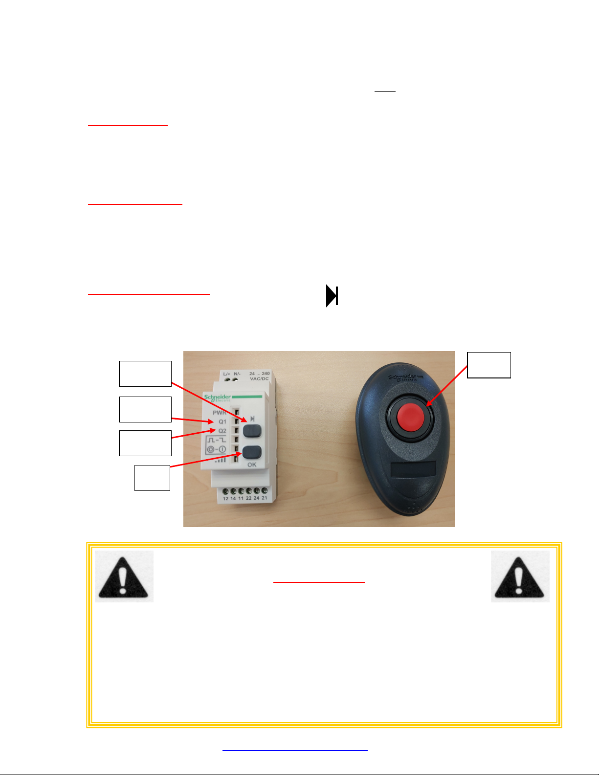
Open all boxes and crates and verify that you have all the required components as well as all your
installation material. Your anti-collision system comes with a control box (see Picture #1), 15FT of 3/4”
liquid tight flexible conduit, one end cap and a 18mm vehicle sensor with 30FT cord (Picture #2).
REMOTESTOP0001
SYSTEM OK
8DCALREMSTP0001
POWER
WASH WORKS
R
M
C
I
T
Y
T
0
MOTOR CITY WASH WORKS
UNIVERSAL HAND HELD
REMOTE STOP SYSTEM
STOPPED
PUSH
TO
RESTART
* USE REMO TE STOP TO TURN OFF
CONVE YOR OR WASH EQU IPMENT
WHE N NEEDED.
* THE MCWW UNIVERSA L REMOTE STOP
CANNOT REPL ACE EMERGENCY
STOP BUTTONS. INSTALL
READILY AVA ILABLE EMERGENCY STOP
BUTTONS ON EAC H SIDE OF THE
WASH BAY.
* WHENEVER AN EMERGENCY STOP
BUTTON IS PUSHED, IT IS TO BE
RESET ONLY BY THE PERSON WHO
INITIALLY STOPPED THE E QUIPMENT
AFTER THE EMERGEN CY.
FA ILU RE T O F OLLOW THESE RULES
M AY LEA DS TO EQUIPMENT DAMAGES,
PERSONAL INJU RI ES OR DEATH!
DANGER!
7ELECHASTRS0001
7CONVELCPNL0001
Picture #1: Control Box w/Remote Transmitters
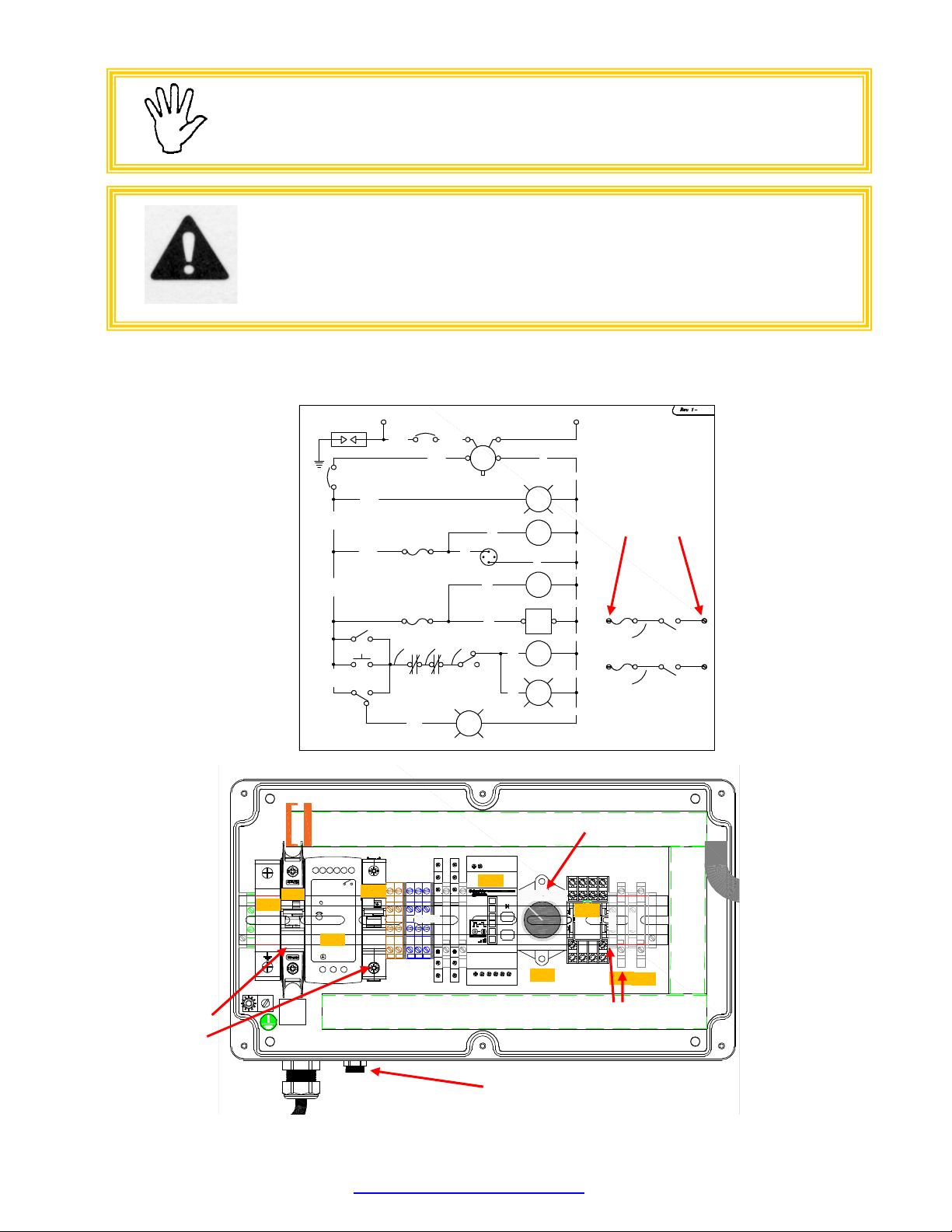
Mount the electrical control box (7CONVELCPNL0001) in a dry area in the mechanical room and in close
proximity to the center of the wash bay (you will need to install the antenna assembly in the middle of the
wash bay, on the mechanical room wall and connect it to the control box).
Mount the antenna assembly in the middle of the wash bay, on the mechanical room wall and about 10ft
off of the floor and connect it to the control box located in the mechanical room.
Picture #2: Antenna Assembly
Connect the control box to a 120VAC, 1PH separate breaker circuit from the building 120VAC sub-panel
(lighting panel).
CABLE CONNECTOR
7ELECHARTRS0001

© Motor City Wash Works, Inc. 48285 Frank, Wixom Michigan 48393 U.S.A. Phone: 248.313.0272 ▪ Fax: 248. 313.0271
8MANULCVRINS003 11-3-20 www.motorcitywashworks.com 3
WARNING!
MATERIAL REQUIRED FOR CONNECTING THE CONTROL
PANEL IS THE CUSTOMER’S RESPONSIBILITY!
ALL WORK HAS TO COMPLY WITH
LOCAL AND NATIONAL CODES!
Connect one of the two sets of “STOP” contacts IN SERIES with the control voltage going to the conveyor
motor starter or IN SERIES with one of the wash E-STOP buttons.
CR1
IDEC
SW2
CR1-1 LIT2
BLUE
LIT1
GREEN
PS1
24VDC
+
-
0V
24VDC
120-240VAC
HARM ONY
HAR1
HAR1
11 14
12
FU2
500ma
+
-
CB2 1A
CB1
1A
120VAC N
OK
POWER
8
12
SW1
BEF1
RED
STOP
12
4
FU1
500ma
2
1
4
3
PLG1
OK1
ALTECH
OK2
ALTECH
24VCB2
PUSH 2 RESTART
AUTO RESTART
24VCB2
0V 0V 0V 0V 0V 0V 0V0V
OK1 OK2
CR1-1
RES1 OK1 OK2
HR1
HR1
FU1
FU1
FU2
FU2
0V
24VCB2 24VCB2
24VCB2
120VAC 120VCB1
CR1-3
CR1-4
6
10
#18AWG YLW
FU3
3A FAST
610
#18AWG YLW
FU3
3A FAST STOP 2
STOP 1
L1
Pic #3: Electrical Schematic
L/+ N/- 2 4 ... 240
VAC/DC
PWR
Q1
Q2
OK
12 14 11 22 24 21
+V +V +V +V
D C OK
D C OK
+V ADJ
+
N L
24VDC
A1
A2
COM
NO
NC
11
14
12
FUSE
24VDC
A1
A2
COM
NO
NC
11
14
12
FUSE
RU4S
24VDC
8
4
5
1
A1 A2
12 91011
6
2
7
3
24V 0VDC
stop1
ABB
FUSE
FUSE
2A D
UL1077
2A D
UL489
L1
MAIN DISC
120VAC
CB1
SS1
PS1
CB2
HAR1
SW1
CB1
FU1 FU2
MANUAL
RE START
AUTO
RES TART
stop2
Pic #4: Panel Assembly
STOP!
CONNECT TO A SEPARATE CIRCUIT ONLY!
NOT DOING SO MAY AFFECT THE OVERALL RELIABILITY OF YOUR
SYSTEM.
CONNECT
HERE
CONNECT
HERE
BREAKER 1
BREAKER 2
CONNECT
ANTENNA HERE
SELECTOR
SWITCH

© Motor City Wash Works, Inc. 48285 Frank, Wixom Michigan 48393 U.S.A. Phone: 248.313.0272 ▪ Fax: 248. 313.0271
8MANULCVRINS003 11-3-20 www.motorcitywashworks.com 4
Turn the power ON to the system and verify that all internal breakers are ON.
Select the mode of operation you prefer by positioning the switch SW1 to “AUTO RESTART” or “MANUAL
RESTART”:
AUTO RESTART:
SELECTING AUTO RESTART WILL ALLOW THE REMOTE STOP SYSTEM TO “STOP” THE
CONVEYOR (IF YOU HAVE CONNECTED THE SYSTEM WITH YOUR E-STOP CIRCUIT FOR
EXAMPLE) AS SOON AS ONE OF THE REMOTE EMITTER’S BUTTONS ARE PRESSED FOR AT
LEAST 0.5 SECONDS. THEN BE READY TO RESTART YOUR CONVEYOR AS SOON AS THE
BUTTON IS RELEASED.
MANUAL RESTART:
SELECTING MANUAL RESTART WILL ALLOW THE REMOTE STOP SYSTEM TO “STOP” THE
CONVEYOR (FOR EXAMPLE) AS SOON AS ONE OF THE REMOTE EMITTER’S BUTTONS IS
PRESSED FOR AT LEAST 0.5 SECONDS, AND THEN KEEP IT STOPPED AS LONG AS THE “PUSH
TO RESTART” BUTTON IS NOT PRESSED.
NOTE: DURING THE PERIOD WHERE THE REMOTE SYSTEM IS IN A “STOPPED” CONDITION, AN
ALARM BEEPER IS ON AS WELL AS A “STOPPER” RED LIGHT IS FLASHING.
ADDING A NEW REMOTE:
Note: In order to add a remote, press the top ‘teach’ button on the receiver, followed by pressing the
stop button on your new remote multiple times until you see either Q1 or Q2 flash on the receiver. Press
the ‘OK’ button. Repeat steps for all additional remotes.
IMPORTANT NOTE:
USE REMOTE STOP TO TURN OFF CONVEYOR OR WASH EQUIPMENT
WHEN NEEDED. THE MCWW UNIVERSAL REMOTE STOP CANNOT REPLACE
EMERGENCY STOP BUTTONS. INSTALL READILY AVAILABLE EMERGENCY
STOP BUTTONS ON EACH SIDE OF THE WASH BAY.
WHENEVER AN EMERGENCY STOP BUTTON IS PUSHED, IT IS TO BE RESET ONLY BY THE
PERSON WHO INITIALLY STOPPED THE EQUIPMENT, AFTER THE EMERGENCY.
FAILURE TO FOLLOW THESE RULES
MAY LEAD TO EQUIPMENT DAMAGE, PERSONAL INJURIES OR DEATH!
TEACH
Q1 LED
Q2 LED
OK
STOP

© Motor City Wash Works, Inc. 48285 Frank, Wixom Michigan 48393 U.S.A. Phone: 248.313.0272 ▪ Fax: 248. 313.0271
8MANULCVRINS003 11-3-20 www.motorcitywashworks.com 5
Warranty and Return Procedure:
Motor City Wash Works warrant this product to be free of defect in material and/or workmanship for a period of
one year from the date of the purchase by the customer from MCWW. During the warranty period MCWW will at
its discretion, at no charge to the customer, repair or replace this product if found defectives, with a new or
refurbished unit, but not to include costs of removal or installation. Any product returned to MCWW for warranty
has to have a Return Material Authorization Number. All shipping cost to MCWW is assumed by the customer.
This is only a summary of MCWW Limited Warranty. Please, communicate with MCWW for our complete
warranty.
Prior to returning any product to MCWW, the customer must call in for Return Material Authorization Number
and a copy of our Return Material Authorization Form filled and completed. The RMA number must be written
clearly on the outside of the shipping package and copy of the form must be included in the package.
Table of contents
Other Motor City Wash Works Cleaning Equipment manuals