MRMC MRMC-1166-02 User manual

ii
SFH-50 Quick Start Guide
QSG Product Code: MRMC-1166-02
Products Covered: MRMC-1483-00, MRMC-1132-01
Modification Date: 4 June 2020
© 2020 Mark Roberts Motion Control Ltd. All rights reserved.
No part of this publication may be reproduced, transmitted, or translated
by any means — graphical, electronic, or mechanical — including
photocopying, recording, taping, or storage in an information retrieval
system, without the express written permission of Mark Roberts Motion
Control.
Although every care has been taken to ensure that the information in this
document is accurate and up to date, Mark Roberts Motion Control
continuously strives to improve their products and may make changes to
the hardware, firmware, and software described in this document. Mark
Roberts Motion Control therefore cannot be held responsible for any
error or omission in this document.
All product names mentioned herein are the trademarks or registered
trademarks of their respective owners.
Contact information
Mark Roberts Motion Control Ltd.
Unit 3, South East Studios
Blindley Heath
Surrey
RH7 6JP
United Kingdom
Telephone: +44 (0) 1342 838000
Web: www.mrmoco.com
www.mrmocorentals.com

SFH-50 Quick Start Guide
iii
SFH-50 Quick Start GuideSFH-50Quick Start Guide
Contents
Chapter 1 Quick Start..................................................................... 1
Safety........................................................................................1
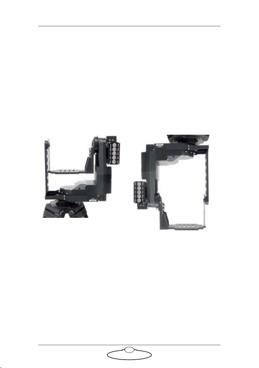
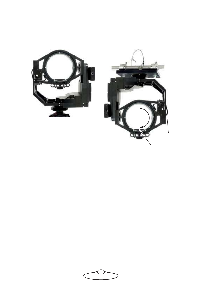
Overview ................................................................................. 1
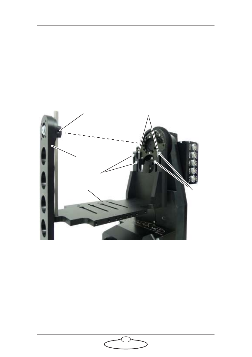
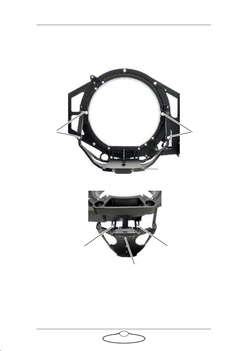
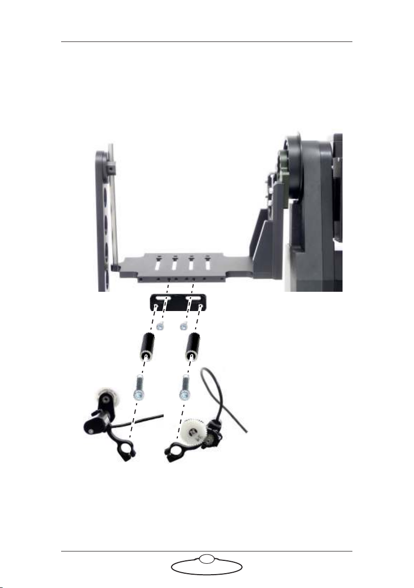
Setting up the hardware ........................................................2
Connecting the cables .........................................................10
Quad-box example, for an SFH-50 head with
stepper motors.............................................................10
Ulti-box example, for an SFH-50 head with
servo motors................................................................12
Your first session ..................................................................14
Subsequent sessions.............................................................17
Appendix 1 Troubleshooting........................................................... 18
Typical symptoms, causes, and actions .............................18
Working with Local Area Networks..................................19
Introduction to LAN addresses ................................19
Managing LAN addresses with Flair........................21
Appendix 2 SFH-50 Panel ............................................................... 25
Introduction to SFH-50 connections ................................25
Interface boxes ............................................................25
Notes on head-controller communication
methods........................................................................25
Quad-box and Octo-box connector summary ................26
Quad-box and Octo-box connector pin-out
information...........................................................................29
Stepper motor connector...........................................29
Power 18-36 Volts connector ....................................29
Serial RS232 connector ..............................................30
Trigger connector (trigger out and in).....................30
Data In connector.......................................................31
Data Out connector....................................................31
Ulti-box connector summary.............................................32
Ulti-box connector pin-out information ..........................34
Servo motor connector ..............................................34
Program serial connector ..........................................34
Power connector .........................................................35
Camera Accessory connector....................................35
Data In connector.......................................................36

SFH-50 Quick Start Guide
1
SFH-50 Quick Start GuideSFH-50Quick Start Guide
Chapter 1 Quick Start
Safety
•Do not use around flammable gas. All electrical equipment can
generate sparks that can ignite flammable gas.
•The head has powerful motors that can pinch, so take care not to get
your hands trapped in the head or cabling.
•Keep the equipment dry. The system has not been made
weatherproof. Do not use with wet hands.
•Keep cables tidy. Use cable ties to keep them out of harm’s way. If
you have a head with slip rings then make use of them; avoid
running any cables between the base and the rotating head or
camera.
Overview
Thank you for using the SFH-50 robotic camera head from Mark Roberts
Motion Control (MRMC). The SFH-50 head is designed for reliable
day-in, day-out use in professional studio environments. The versatility of
the SFH-50 makes it suitable for live action, stills, and time-lapse
applications.
You can connect your SFH-50 to any MRMC controller, such as a PC
running Flair Motion Control Software or one of the MSA-based
controllers such the Large Flat Panel (LFP), MSA-20 Handwheels,
Joystick Controller, or Mini MSA.

SFH-50 Quick Start Guide
2
Setting up the hardware
1. Mount the SFH-50 head onto your choice of support, such as a
heavy-duty tripod or metal plate. The head can be over-slung
(sitting on a tripod or platform) or under-slung (hanging from its
mount).
Further details about mounting specifications are described in
Appendix 3 Specifications.
SFH-50 with Support Arm:
Over-slung Under-slung

SFH-50 Quick Start Guide
3
SFH-50 with Roll Ring:
Hint
If your SFH-50 has a Roll Ring and you use under-slung
mounting, move the camera platform to the bottom
(lowermost) position by manually rotating the Roll Ring 180°.
Do not move the camera platform to the bottom by inverting
the Tilt, as doing this will twist the Roll motor cable that goes
through the Tilt axle.
Over-slung on a tripod
Roll
Cable
Platform
180°
Under-slung from a scaffolding
plate. For details see page 45.

SFH-50 Quick Start Guide
4
2. Adjust the height of the camera platform relative to the head, so that
the camera lens will be at the same height as the Tilt axis (and
centred in the optional Roll Ring) when the camera is mounted later.
Do not adjust the platform height when a camera is mounted.
To adjust the height on an SFH-50 with a Support Arm, loosen the
five retaining bolts that hold the camera platform in place (one on
the Support Arm, then four on the main platform arm), turn the
two height adjustment bolts to achieve the platform height you
want, then re-tighten the five retaining bolts.
Loosen
Loosen
Platform
Loosen this one first,
tighten last
Height adjustment bolts
Tilt axis
Support Arm
Platform

SFH-50 Quick Start Guide
5
To adjust the height on an SFH-50 with a Roll Ring, loosen the six
retaining bolts that hold the camera platform in place (four in the
rear, two in the front), turn the height adjustment bolt to achieve the
platform height you want, then re-tighten the six retaining bolts.
Loosen Loosen
Rear view:
Loosen Loosen
Height adjustment bolt
Front view:
Platform

SFH-50 Quick Start Guide
6
3. If you are using external Lens Control Motors (LCMs) mounted on
the head, bolt the mounting rods onto the head, then mount the
LCMs onto the rods in approximately the correct position. You can
fine-tune the position later.
SFH-50 with Support Arm:
Mounting
rods
LCM: Zoom
LCM: Focus

SFH-50 Quick Start Guide
7
SFH-50 with Roll Ring:
Mounting
rods
LCM: Zoom
LCM: Focus

SFH-50 Quick Start Guide
8
4. Place the camera on the platform, move the camera forward or
backward to balance the platform in Tilt, then insert the camera
mounting bolts under the platform and into the bottom of the
camera housing and tighten firmly.
SFH-50 with Support Arm:
SFH-50 with Roll Ring:

SFH-50 Quick Start Guide
9
You normally mount the camera with the lens pointing through the
Roll Ring, but you can mount it backwards (pointing away from the
ring) if you want.
5. If you are using head-mounted Lens Control Motors (LCMs), adjust
their position on the rods so that the LCM gears mesh firmly with
the lens gears.

SFH-50 Quick Start Guide
10
Connecting the cables
Quad-box example, for an SFH-50 head with stepper
motors
24V 5A
#1 PAN
#2 TILT
#3 ROLL
ETHERNET
Rear
Front
Example controller:
MSA-20 Handwheels
POWER
18-36V
Quad-box
Quad-box
The head and
controller both use
the same type of
power supply brick.
Attach the power cables last.

SFH-50 Quick Start Guide
11
Connectors #1-#4 on the Quad-box are identical and can be used for any
stepper motors. The diagram shows a typical application. Attach the
power cables last.
The controller can be any MRMC controller such as a PC running Flair
Motion Control Software or one of the MSA-based controllers such the
Large Flat Panel (LFP), MSA-20 Handwheels, Joystick Controller, or Mini
MSA.
Hint
If you use a dedicated controller that has a POWER OUT socket, you
should not use this socket to power the head if you are using
Ethernet to connect the head to the controller. If you do so then
powering up the controller will simultaneously power up the head,
and in this case powering up two Ethernet devices at the same time
on the same network can cause communication problems between
them.

SFH-50 Quick Start Guide
12
Ulti-box example, for an SFH-50 head with servo motors
24V 5A
PAN
ETHERNET
Rear
Front
Example:
MSA-20 Handwheels
POWER
Attach the power cables last.
Ulti-box
Ulti-box
TILT
TILT
PAN
The head and
controller both use
the same type of
power supply brick.

SFH-50 Quick Start Guide
13
The controller can be any MRMC controller such as a PC running Flair
Motion Control Software or one of the MSA-based controllers such the
Large Flat Panel (LFP), MSA-20 Handwheels, Joystick Controller, or Mini
MSA.
Hint
If you use a dedicated controller that has a POWER OUT socket, you
should not use this socket to power the head if you are using
Ethernet to connect the head to the controller. If you do so then
powering up the controller will simultaneously power up the head,
and in this case powering up two Ethernet devices at the same time
on the same network can cause communication problems between
them.

SFH-50 Quick Start Guide
14
Your first session
Instructions for using the SFH-50 head with a specific controller, or with
Flair Motion Control Software running on a PC, are beyond the scope of
this manual. The first time you use the head you typically need to
perform the steps given below. Refer to the manual that came with your
controller or software for details.
1. Attach the power cables to the head and controller.
There is no power switch on the SFH-50 head; the power is
on whenever the 24-volt power supply is attached and live.
After you have attached the power cable, make sure the
power indicator LED on the head lights up.
Similarly, to turn off the head you simply remove the power cable.
All MRMC controllers and heads have robust electronics that are
designed to withstand the rigours of connection and disconnection
to live power cables.
2. Load the head.
The head does not retain any operating system when it is switched
off, so when you turn on the head you must load the head operating
system from the attached controller or PC.
For example to load the head from an MSA-based controller from
MRMC (such as the LFP, MSA-20 Handwheels, Joystick Controller,
or Mini MSA) you press the SELECT knob on the controller when
prompted to do so. Different head models and controller-head
connection methods use different operating systems, so be sure that
the operating system that you load from your controller is the
Hint
It is a good idea to attach the power cables last, after all the
other cables are in place.
It is also recommended that you power up the controller last,
after powering up the head if you are using Ethernet to connect
the head to the controller, as powering up two devices
simultaneously on the same Ethernet network can cause
communication problems.
Power
LED

SFH-50 Quick Start Guide
15
correct one for your particular SFH-50 head model and connection
method.
3. Set the control directions.
In your controller or software you need to specify the directions of
the focus, zoom and joystick/handwheel controls for your particular
head, lens gearing attachments, and preference. For example, some
people prefer the camera to point upward when the joystick is pulled
back, while others prefer the opposite logic whereby pushing
forward (“up”) on the joystick targets the camera upward in the
scene.
For example to set the control directions on an LFP controller you
use the menu option SET DIRECTION. On the MSA-20 Handwheels,
Joystick Controller, or Mini MSA you can use the same menu option
or use the FWD and REV hardware switches.
4. Zero the axes.
At the beginning of each session, after loading the head, you need to
zero the axes. This defines a base position at which all head
positions and lens settings are set to zero (0) in the controller or
software. All limits, lens controls, preset positions, and moves that
are stored in the controller or software are measured relative to this
base position. The zero points themselves are not stored in the head
or lens when the power is off, so you need to define them at the start
of each session, by zeroing the axes. Controllers usually offer two
different ways to zero the axes: an automatic method and a manual
method:
In the automatic method (sometimes called homing), the
controller physically moves the axes to the home positions that
are built into the hardware (if your head has the optional
homing facility) and then assigns these positions as the zero
points for the axes. For example to automatically zero the axes
with an MSA-based controller (such as the LFP, MSA-20
Handwheels, Joystick Controller, or Mini MSA) you can go
into film mode and use the menu option HOME AXES >ALL
AXES.
In the manual method (sometimes called direct zeroing) you
use the controls to point the camera head in the direction that
you want to use as the zero position for the head axes and then
manually set the current axes positions as the zero points. For

SFH-50 Quick Start Guide
16
example to directly set the current axes positions as the zero
points on an MSA-based controller you use the menu option
DIRECT ZERO ALL.
Hints
If you plan on having several manually zeroed sessions at the
same site then you should pick an object in the camera’s field of
view that you can use as the zero position for the head for every
session. The object should be easily identifiable, stationary, and
repeatable, such as the corner of a ceiling.
To zero the axes with external Lens Control Motors you first set
the focus to infinity (), zoom to wide-angle (zoomed out all
the way), iris/aperture to wide open. You then use the
controller to zero all the axes — either automatically or
manually.
If you are using the head in an underslung configuration it is
recommended that you use the manual method for zeroing the
axes. Depending on the controller or software settings, the
automatic method might pan or tilt the camera into a home
orientation that is 180° from your working target orientation,
which can be potentially awkward or risky for the attached
equipment.
Hint
The homing facility on the SFH-50 head uses optical sensors
(with homing fins) on the Pan and Tilt axes. The optional Roll
facility uses a magnetic sensor. There are two magnets on the
Roll ring, so the Roll homing facility will work for both
over-slung and under-slung mount configurations. For either
configuration, note that the camera platform is not horizontal
in the Roll home position. This is intentional, as it makes the
homing procedure quick and directionally reliable when you
invoke the homing facility from a typical horizontal (or
near-horizontal) platform starting position, whether the camera
is over-slung or under-slung.
This manual suits for next models
3
Table of contents
Other MRMC Camera Accessories manuals

MRMC
MRMC MRMC-1096-00 User manual

MRMC
MRMC MRMC-1502-04 User manual

MRMC
MRMC Pan Bars User manual

MRMC
MRMC Robotic Pod User manual

MRMC
MRMC Robotic Pod User manual

MRMC
MRMC MRMC-2016-00 User manual

MRMC
MRMC NUCLEUS-M LENS MOTOR User manual

MRMC
MRMC Pan Bars User manual

MRMC
MRMC MRMC-1167-02 User manual

MRMC
MRMC SFH-50 User manual