MRMC MRMC-1167-02 User manual

Quick Start Guide
Document version: AFC-QSG-20160421
Part number: MRMC-1167-02
AFC
Head

ii
AFC Quick Start Guide
Document version: AFC-QSG-20160421
Part number: MRMC-1167-02
© 2016 Mark Roberts Motion Control Ltd. All rights reserved.
No part of this publication may be reproduced, transmitted, or translated
by any means — graphical, electronic, or mechanical — including
photocopying, recording, taping, or storage in an information retrieval
system, without the express written permission of Mark Roberts Motion
Control.
Although every care has been taken to ensure that the information in this
document is accurate and up to date, Mark Roberts Motion Control
continuously strives to improve their products and may make changes to
the hardware, firmware, and software described in this document. Mark
Roberts Motion Control therefore cannot be held responsible for any
error or omission in this document.
All product names mentioned herein are the trademarks or registered
trademarks of their respective owners.
Contact information
Mark Roberts Motion Control Ltd.
Unit 3, South East Studios
Blindley Heath
Surrey
RH7 6JP
United Kingdom
Telephone: +44 (0) 1342 838000
E-mail: info@mrmoco.com (sales and general enquiries)
Web: www.mrmoco.com
www.mrmocorentals.com

AFC Quick Start Guide
iii
AFC Quick Start GuideAFCQuick Start Guide
Contents
Chapter 1 Quick Start..................................................................... 1
Safety........................................................................................1
Overview .................................................................................1
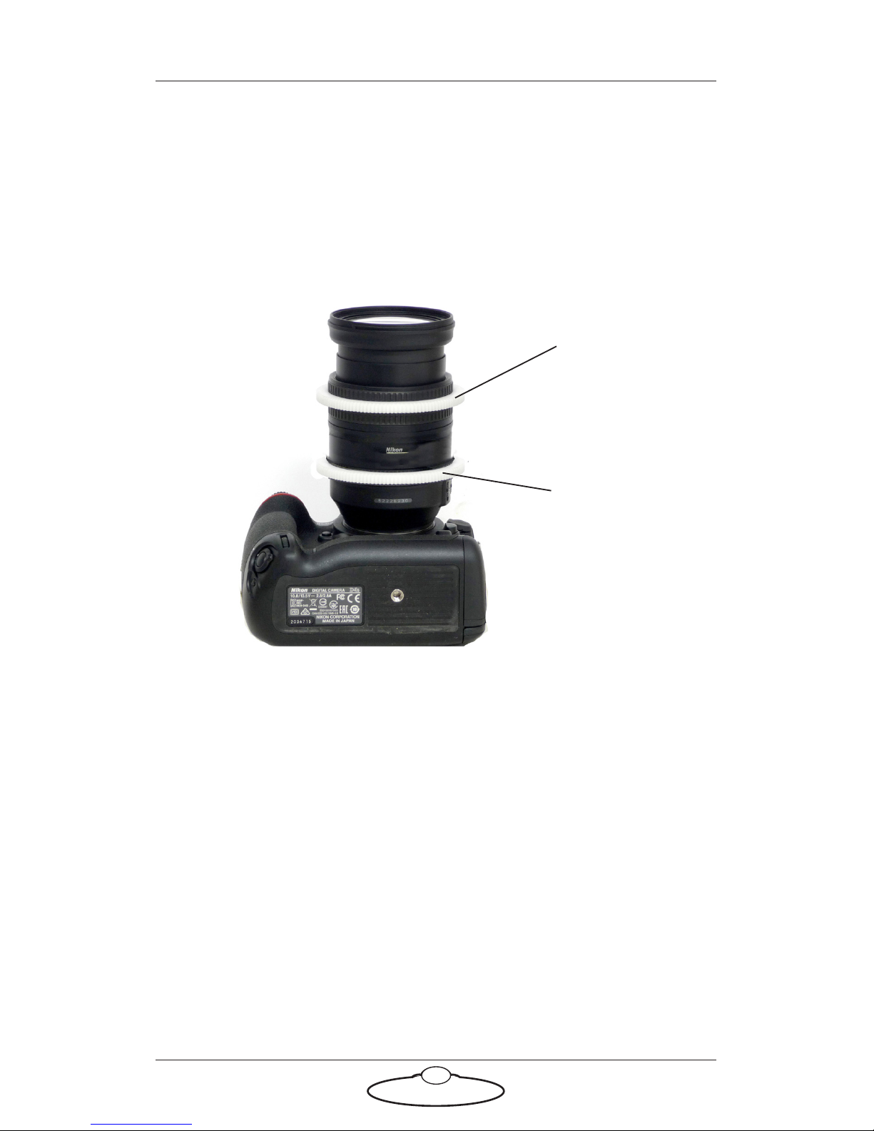
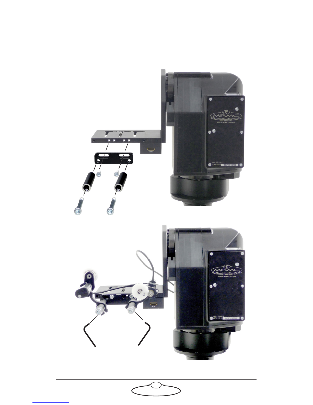
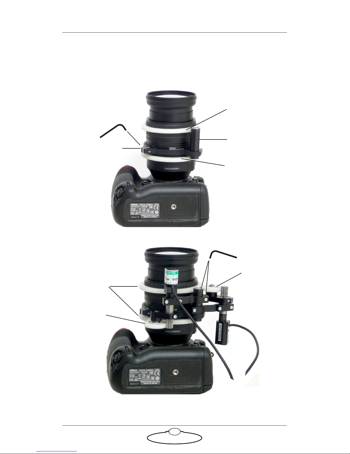
Setting up the hardware ........................................................2
Connecting the cables .........................................................10
Video camera example ...............................................10
DSLR camera example ...............................................12
Your first session ..................................................................14
Subsequent sessions.............................................................17
Appendix 1 Troubleshooting........................................................... 18
Typical symptoms, causes, and actions .............................18
Working with Local Area Networks ..................................19
Introduction to LAN addresses ................................19
Managing LAN addresses with Flair........................21
Appendix 2 AFC Back Panel ........................................................... 25
Connector summary............................................................25
Panel BCST 033 and base unit panel BCST 062 .....26
Panel BCST 043 and base unit panel BCST 036 .....28
Panel BCST 048 without slip rings ...........................32
Panel BCST 060 and base unit panel BCST 062 .....34
Panel BCST 070 without slip rings ...........................36
Connector pin-out information.........................................38
12V Out connector (small DC jack) ........................38
12V Out connector (small resetable DC jack)........38
12V Out connector (large 4-way XLR)....................38
Video connector..........................................................39
Video Sync connector ................................................39
Trigger connector (standard trigger out) ................40
Trigger connector (trigger out and in).....................40
Serial (digital) lens connector for internal servo
LCMs ............................................................................40
Focus, Zoom, Iris lens connectors for external
servo LCMs..................................................................41
AUX-1 and AUX-2 lens connectors for external
stepper LCMs ..............................................................41
Analog lens connector ...............................................42
Power 24V connector.................................................42

AFC Quick Start Guide
iv
Appendix 3 Specifications............................................................... 43

AFC Quick Start Guide
1
AFC Quick Start GuideAFCQuick Start Guide
Chapter 1 Quick Start
Safety
•Do not use around flammable gas. All electrical equipment can
generate sparks that can ignite flammable gas.
•The head has powerful motors that can pinch, so take care not to get
your hands trapped in the head or cabling.
•Keep the equipment dry. The system has not been made
weatherproof. Do not use with wet hands.
•Keep cables tidy. Use cable ties to keep them out of harm’s way. If
you have a head with slip rings then make use of them; avoid
running any cables between the base and the rotating head or
camera.
Overview
Thank you for using the AFC robotic camera head from Mark Roberts
Motion Control (MRMC). The AFC head is an Accurate, Fast, and
Compact head designed for reliable day-in, day-out use in professional
studio and Outside Broadcast environments. The versatility of the AFC
head makes it suitable for live action, stills, and time-lapse applications.
You can use the Ethernet connection on the AFC head to connect directly
or remotely to an MRMC controller such as a PC running Flair Motion
Control Software, or to one of the dedicated MSA-based controllers such
as the Large Flat Panel (LFP), MSA-20 Handwheels, or Mini MSA.

AFC Quick Start Guide
2
Setting up the hardware
1. Mount the AFC head onto your choice of support, such as a
heavy-duty tripod or metal plate.
More information on mounting sockets and dimensions can be
found in Appendix 3 Specifications.
Example: AFC head
mounted directly onto
tripod with single
3/8-16 tripod
mounting bolt:
Example: AFC head
mounted on an
optional riser mounted
on a table, to give the
head more height and
Tilt clearance. Further
details are on page 48.

AFC Quick Start Guide
3
Example: AFC head
underslung and
directly mounted onto
scaffolding plate.
Further details are on
page 50.
For notes on zeroing
the axes when using an
underslung
configuration, see page
16.
Example: AFC head
underslung and
mounted onto riser
which is, in turn,
mounted onto a
scaffolding plate.
Further details are on
page 51.

AFC Quick Start Guide
4
2. If you are using serial (digital) Lens Control Motors (LCMs) for
focus, zoom, and iris (aperture) then skip this step and go on to step
3 on page 7.
If you are using optional external (LCMs) then these are ordinarily
made to your lens specifications. Set these up now as follows:
2.1 Install the large gears onto the focus, zoom, and iris rings of
your lens, as applicable.
The relative position of the rings depends on the make and
model of the lens.
Lens gear
Lens gear
(Zoom)
(Focus)

AFC Quick Start Guide
5
2.2 For head-mounted LCMs, bolt the mounting rods onto the
head, then mount the LCMs onto the rods in approximately
the correct position. You can fine-tune the position later:
Mounting
rods

AFC Quick Start Guide
6
2.3 For lens-mounted LCMs, attach the mounting ring onto the
lens so it does not interfere with the focus, zoom, or iris rings,
then mount the LCMs onto the rod, making sure that the LCM
gears mesh firmly with the lens gears:
Mounting ring
Mounting rod
Lens gears
LCM gear
LCM gear
Lens gear
Lens gear
(Zoom)
(Focus)

AFC Quick Start Guide
7
3. Place the camera on the platform, move the camera forward or
backward to balance the platform in Tilt, then insert the camera
mounting bolts under the platform and into the bottom of the
camera housing and tighten firmly.
Video camera,
overslung
Video camera,
underslung

AFC Quick Start Guide
8
4. If you are using head-mounted LCMs, adjust their position on the
rods so that the LCM gears mesh firmly with the lens gears.
DSLR camera

AFC Quick Start Guide
9
Notes

AFC Quick Start Guide
10
Connecting the cables
Video camera example
AFC head with BCST 043 panel, BCST 036 base, GV LDX Compact video
camera, Fujinon Digipower A22x7.8BERD-S28B Serial (digital) Lens
Control Motors, and Windows PC running Flair Motion Control
Software.
Power DC in
VIDEO
HD SDI (A)
Rear view
Front view
BCST 043 panel
Serial Lens
Control Motors
SERIAL
ETHERNET
LENS
ETHERNET
12V OUT
REF
SYNC

AFC Quick Start Guide
11
The controller can be any MRMC controller such as the Large Flat Panel
(LFP), MSA-20 Handwheels, Joystick Controller, Mini MSA, or a PC
running Flair Motion Control Software.
24V 5A
Attach the
power cables
last.
BCST 043 panel
BCST 036 base
SYNC
POWER 24V
VIDEO OUT
ETHERNET
PC running Flair Motion
Control Software

AFC Quick Start Guide
12
DSLR camera example
AFC head with BCST 060 panel, BCST 062 base, Nikon D4s camera,
external Lens Control Motors, and LFP controller.
TRIGGER
TRIGGER
12V OUT
RESETABLE
12V IN
HDMI
HDMI
VIDEO
SDI
12V OUT FOCUS
ZOOM
Rear view
Front view
BCST 060 panel
External Lens
Optional
HDMI/SDI
Control Motors
5V~12V
converter

AFC Quick Start Guide
13
The controller can be any MRMC controller such as the Large Flat Panel
(LFP), MSA-20 Handwheels, Joystick Controller, Mini MSA, or a PC
running Flair Motion Control Software.
LFP Controller
24V 5A
POWER 24V
ETHERNET
VIDEO OUT
Attach the
power cables
last.
BCST 060 panel
BCST 062 base
The head and controller
both use the same type of
power supply brick.

AFC Quick Start Guide
14
Your first session
Instructions for using the AFC head with a specific controller, or with
Flair Motion Control Software running on a PC, are beyond the scope of
this manual. When you want to use the head you typically need to
perform the steps given below. Refer to the manual that came with your
controller or software for details.
1. Attach the cables to the head and controller, as described in the
previous section.
There is no power switch on the AFC head; the power is on
whenever the 24-volt power supply is attached and live. After you
have attached the power cable, make sure the power indicator LED
() on the head lights up.
Similarly, to turn off the head you simply remove the power cable.
All MRMC controllers and heads have robust electronics that are
designed to withstand the rigours of connection and disconnection
to live power cables.
Hint
If you use a dedicated controller that has a POWER OUT socket, you
should not use this socket to power the head. If you do so then
powering up the controller will simultaneously power up the head,
and in this instance powering up two Ethernet devices at the same
time on the same network can cause communication problems
between them.
Hint
It is a good idea to attach the power cables last, after all the
other cables are in place.
It is also recommended that you power up the controller last,
after powering up the head, as powering up two devices
simultaneously on the same Ethernet network can cause
communication problems.

AFC Quick Start Guide
15
2. Load the head.
The head does not retain any operating system when it is switched
off, so when you turn on the head you must load the head operating
system from the attached controller or PC.
For example to load the head from an MSA-based controller you
press the SELECT knob on the controller when prompted to do so.
Different head models use different operating systems, so be sure
that the operating system that you load from your controller is the
correct one for your particular AFC head model.
3. Set the control directions.
In your controller or software you need to specify the directions of
the focus, zoom and joystick or wheel controls for your particular
head, lens gearing attachments, and preference. For example, some
people prefer the camera to point upward when the joystick is pulled
back, while others prefer the opposite logic whereby pushing
forward (“up”) on the joystick targets the camera upward in the
scene.
For example to set the control directions on an LFP controller you
use the menu option SET DIRECTION. On the MSA-20 Handwheels,
Joystick Controller, or Mini MSA Controller you can use the same
menu option or use the FWD and REV hardware switches.
4. Zero the axes.
At the beginning of each session, after loading the head, you need to
zero the axes. This defines a base position at which all head
positions and lens settings are set to zero (0) in the controller or
software. All limits, lens controls, preset positions, and moves that
are stored in the controller or software are measured relative to this
base position. The zero points themselves are not stored in the head
or lens when the power is off, so you need to define them at the start
of each session, by zeroing the axes. Controllers usually offer two
different ways to zero the axes: an automatic method and a manual
method:
In the automatic method (sometimes called homing), the
controller physically moves the axes to the home positions that
are built into the hardware (if your AFC head has the optional
homing facility) and then assigns these positions as the zero
points for the axes. For example to automatically zero the axes

AFC Quick Start Guide
16
with an MSA-based controller you can go into film mode and
use the menu option HOME AXES >ALL AXES.
In the manual method (sometimes called direct zeroing) you
use the controls to point the camera head in the direction that
you want to use as the zero position for the head axes and then
manually set the current axes positions as the zero points. For
example to directly set the current axes positions as the zero
points on an MSA-based controller you use the menu option
DIRECT ZERO ALL.
5. Set the limits.
In order to prevent damage to cables and other equipment, you can
set limits to the range of physical travel of the head movement and
lens controls. This is especially important if you have a head without
slip rings, where cabling can get wrapped around the head, or if you
have a lens with external control motors.
For example to set the limits on an MSA-based controller you use
the menu option SET SOFT LIMITS.
Hints
If you plan on having several manually zeroed sessions at the
same site then you should pick an object in the camera’s field of
view that you can use as the zero position for the head for every
session. The object should be easily identifiable, stationary, and
repeatable, such as the corner of a ceiling.
To zero the axes with external Lens Control Motors you first set
the focus to infinity (), zoom to wide-angle (zoomed out all
the way), and iris/aperture to wide open. You then use the
controller to zero all the axes — either automatically or
manually.
If you are using the AFC head in an underslung configuration
it is recommended that you use the manual method for zeroing
the axes. Depending on the controller or software settings, the
automatic method might pan or tilt the camera into a home
orientation that is 180° from your working target orientation,
which can be potentially awkward or risky for the attached
equipment.
Table of contents
Other MRMC Camera Accessories manuals

MRMC
MRMC MRMC-1096-00 User manual

MRMC
MRMC Robotic Pod User manual

MRMC
MRMC MRMC-1488-00 User manual

MRMC
MRMC NUCLEUS-M LENS MOTOR User manual

MRMC
MRMC MRMC-2016-00 User manual

MRMC
MRMC Robotic Pod User manual

MRMC
MRMC SFH-50 User manual

MRMC
MRMC Pan Bars User manual

MRMC
MRMC MRMC-1502-04 User manual

MRMC
MRMC MRMC-2318-00 User manual
Popular Camera Accessories manuals by other brands

KOPFJAGER
KOPFJAGER KJ89002 user manual

dji
dji OSMO quick start guide

Aigis Mechtronics
Aigis Mechtronics HS948 Series Installation and operating instructions

KiloVault
KiloVault HAB Series Installation and user manual

Bioenno Power
Bioenno Power BLF-0603W user manual

IINNO Energy
IINNO Energy M4856-P user manual