MSG Equipment MS005 User manual
2022.09.07
MS005
TEST BENCH FOR DIAGNOSTICS
OF ALTERNATORS AND STARTERS
USER MANUAL
STANOWISKO DIAGNOSTYCZNE DO
TESTOWANIA ALTERNATORÓW I ROZRUSZNIKÓW
INSTRUKCJA OBSŁUGI
СТЕНД ДЛЯ ДИАГНОСТИКИ ГЕНЕРАТОРОВ И СТАРТЕРОВ
РУКОВОДСТВО ПО ЭКСПЛУАТАЦИИ
UNIQUENESS
TRAINING
SERVICE
INNOVATIO
N
WARRANTY
QUALITY


English
User manual
3
CONTENTS
INTRODUCTION....................................................................................................................................................4
1. APPLICATION....................................................................................................................................................4
2. SPECIFICATIONS..............................................................................................................................................5
3. EQUIPMENT SET .............................................................................................................................................. 7
4. TEST BENCH DESCRIPTION.......................................................................................................................... 8
5. APPROPRIATE USE........................................................................................................................................13
5.1. Safety Guidelines ...............................................................................................................................13
5.2. Installation and connection of test bench..................................................................................14
6. TEST BENCH MAINTENANCE........................................................................................................................15
6.1. Test bench software update............................................................................................................15
6.2. Cleaning and care..............................................................................................................................15
7. TROUBLESHOOTING GUIDE.........................................................................................................................16
8. RECYCLING..................................................................................................................................................... 17
CONTACTS...........................................................................................................................................................18

English
Test bench MS005
4
INTRODUCTION
We appreciate you have chosen the products of TM MSG equipment.
The present user manual consists of the information on the application, supply slip, design,
specifications and rules of usage of test bench MS005.
Prior to using the test bench MS005 (hereinafter, “the bench”), study the present user manual
thoroughly. If required, get the special training at bench manufacturer facilities.
Due to the permanent improvements of the bench, the design, supply slip and software are
subject to modifications that are not included to the present user manual. Pre-installed bench
software is subject to update. In future, its support may be terminated without a prior notice.
1. APPLICATION
The bench is designed to check the technical condition of the automotive alternators with
different connection terminals, alternators of system «start-stop» 12V, starters and 12V
automotive lead-acid storage batteries.
The bench displays the measured parameters in real time oscillographically that allows to see the
broad picture of unit operation, and to make more accurate check of unit condition.
The diagnostics of automotive alternators takes into account the following criteria:
- stabilizing voltage;
- control lamp working performance capacity;
- displaying of the frequency and FR duty ratio (voltage regulator response);
- the AC pulsation value.
Additionally - for COM alternator types:
- ID;
- protocol;
- data exchange speed;
- LIN protocol type;
- regulator self-diagnostics errors.
The diagnostics of the automotive starters considers the voltage changes nature and the currents
on the terminals 30, 45 and 50 during the starter operation.

English
User manual
5
2. SPECIFICATIONS
Main
Supply voltage, V
400
Supply mains type
Three phase
Drive power, kW
7.5
Dimensions (L x W x H), mm
655×900×1430
Weight, kg
130
Quantity of storage batteries
(not included into supply slip) 2 similar lead-acid by 12V
Battery capacity
45Ah min
Storage battery automatic charging No.1
Yes
Storage battery automatic charging No.2
Yes
Rated voltage of the diagnosed units, V
12, 24
Maximum overall length of the diagnosed
unit, mm (m) 410 (0,41)
Alternator diagnostics
Load, A
12V
300А
24V
150А
Verification regime
Automatic/manual
Load adjustment (0-100%)
Smoothly
Drive speed, rpm
0-3000
Drive speed adjustment
Smoothly
Drive type (alternator drive)
V-belt drive/Poly V-belt drive
Types of diagnosed alternators 12V
Lamp, SIG, RLO, RVC, C KOREA, P-D,
C JAPAN, COM (LIN, BSS), «S/A PSA»
24V
Lamp, COM (LIN)
Starter diagnostics
Power of diagnosed starters, kW
up to 11

English
Test bench MS005
6
Measured parameters
The charts displaying the operation starting
mode, voltage variations and voltage
current on the terminals: К30, К50 и К45
Storage battery diagnostics
Types of diagnosed storage batteries
Any lead-acid storage batteries 12V
Measured parameters
Capacity
Additional features
Display
Touch Screen 12”
Software update
Available
Alternator database
Available
Diagnostics results storage
Available
Printing
Available
Internet connection
Wi-Fi (802.11 a/b/g/ac), Ethernet
Connection of peripheral devices
2 x USB 2.0

English
User manual
7
3. EQUIPMENT SET
The equipment set includes:
Item name
Number of
pcs
Test bench MS005
1
MS33001 – a cable with a kit of adapting wires - for the connection to
alternator connector 1
Cable for starter diagnostics
1
Alternator positive terminal adapter
2
MS0114 - Cutout fuse (type 22x58 mm, current 100А)
1
Stylus
1
Bench door keys
2
Module Wi-Fi
1
Socket 400V
1
User Manual (card with QR code)
1

English
Test bench MS005
8
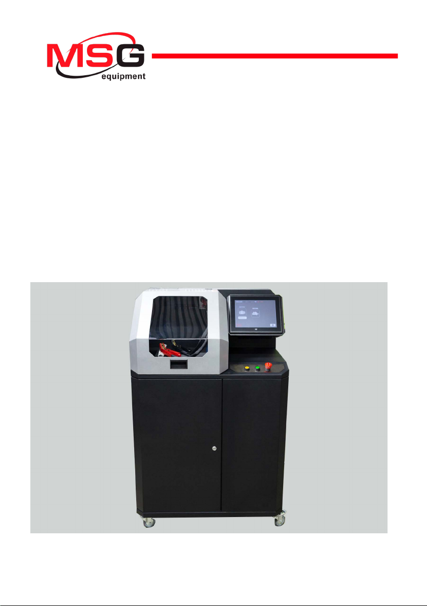
4. TEST BENCH DESCRIPTION
Figure 1. Overall view of test bench
1– Access door to storage battery location.
2– Working spot.
3– Protective housing.
4– Touch screen - to display diagnostic parameters of a diagnosed unit and to control the bench
functions.
5– Control panel.
6– Pivot wheels with brake.
English
User manual
9
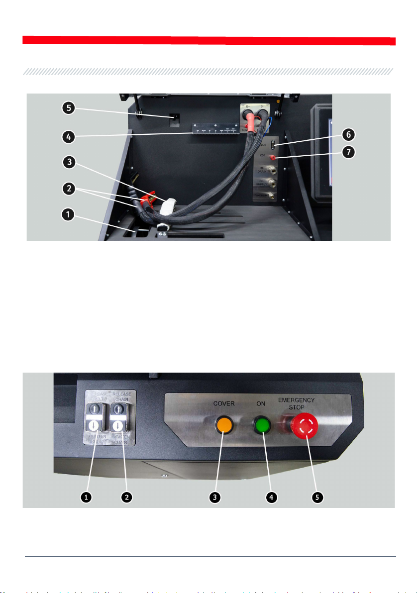
The working spot (fig.2) consists of the following components:
Figure 2. Bench working spot
1– Alternator drive belts: V-belts and poly V-belts.
2– Power cables «В+» «В-».
3– Unit fixing chain.
4– The bracket for a diagnostic cable alligator clips.
5– Thermal vision camera.
6– Diagnostic cable connection port.
7– Diagnostic cable connection port for starter diagnostics.
The control panel (fig.3) consists of:
Figure 3. Bench control panel
1– buttons to control the tightening and loosening of alternator drive belt.
English
Test bench MS005
10
2– buttons to control the tightening and loosening of unit fixing chain.
3– button «COVER» - opens the protective housing.
4– button «OFF/ON» - is responsible for the power on the bench. The bench is turned off by
pressing the button «Turn off the bench» in the main menu of the service program.
5– Button «EMERGENCY STOP» - emergency stop of generator drive and chain/belt tightening.
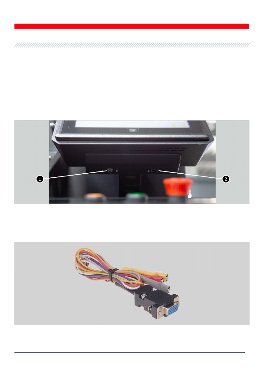
In the bottom of the touch screen there are two USB ports (fig.4 ref. 1) for connecting the computer
periphery (mouse, keyboard, WiFi adapter) and network LAN port (ref. 2).
Figure 4. Position of USB and LAN ports
The bench supply slip includes the diagnostic cable (fig.5) that consists of the adapting wire kit
(fig.6) - for more convenient connection to alternator connection terminals.
Figure 5. Diagnostic cable MS-33001
Table of contents
Languages:
Other MSG Equipment Test Equipment manuals

MSG Equipment
MSG Equipment MS800 User manual

MSG Equipment
MSG Equipment MS603N User manual

MSG Equipment
MSG Equipment MS008 User manual

MSG Equipment
MSG Equipment MS031 User manual

MSG Equipment
MSG Equipment MS016 User manual

MSG Equipment
MSG Equipment MS1000+ User manual

MSG Equipment
MSG Equipment MS002 COM User manual

MSG Equipment
MSG Equipment MS300 User manual

MSG Equipment
MSG Equipment MS016 User manual

MSG Equipment
MSG Equipment MS1000+ User manual


