MSG Equipment MS121 User manual

2019.11.20
MS121
USER MANUAL
TESTER FOR ELECTROMAGNETIC VALVES AND CLUTCHES OF AIR
CONDITIONING COMPRESSORS
INSTRUKCJA OBSŁUGI
TESTER DO SPRZĘGIEŁ ELEKTROMAGNETYCZNYCH I ZAWORÓW
SPRĘŻAREK KLIMATYZACYJNYCH
РУКОВОДСТВО ПО ЭКСПЛУАТАЦИИ
ТЕСТЕР ДЛЯ ПРОВЕРКИ ЭЛЕКТРОМАГНИТНЫХ МУФТ И КЛАПАНОВ
КОМПРЕССОРОВ АВТОМОБИЛЬНЫХ КОНДИЦИОНЕРОВ
QUALITY UNIQUENESSINNOVATION TRAININGSERVICEWARRANTY

User Manual – Tester MSG MS121
2
1. DESCRIPTION....................................................................................................................................................
3
2. TECHNICAL CHARACTERISTICS......................................................................................................................3
3. CONTROL UNITS................................................................................................................................................3
3.1 Buttons............................................................................................................................................................ 5
3.2 Terminals........................................................................................................................................................ 6
3.3 Menu................................................................................................................................................................ 6
1. SETTING INTO OPERATION............................................................................................................................. 6
2. STEP-BY-STEP INSTRUCTION.........................................................................................................................6
3. SEFETY MEASURES WHILE OPERATION ........................................................................................................... 11
4.CONTACTS ................................................................................................................................................................ 11
CONTENTS

3
User Manual – Tester MSG MS121
1. DESCRIPTION
Tester MS121 is a multifunctional device combining two options: testing of electromagnetic
valves and control valves of AC system. The device has a high measurement accuracy, can
be used as a PWM generator which is a high-demand function in the work of modern
workshops. Tester MS121 is designed to test the electromagnetic clutches and control valves
of the vehicle air conditioning compressor. The principle of the device is to transmit PWM
signals when checking the valve and the clutch. The tester operation is user-friendly thanks
to the color 4.3" TFT display and convenient menu. Diagnostics of AC compressors can be
performed either separately from the vehicle or directly on the it. The tester is presented
in a metal housing and is resistant to the effects of lubricants. The presence of several
stages of protection makes the tester resistant to improper connections, and the color
marking of the connection pins makes it possible to minimize the possibility of incorrect
connection.

User Manual – Tester MSG MS121
General
Color TFT-LCD display
Testing of clutches
Diagonal - 4,3”
Supply voltage, V 12V
Supplytype 12 battery, vehicle on-board network
Power temperature, °С 0…+40
Storagetemperature,°C
Testedparameters
-10…+40
Relative humidity, % ≤75% for 0…+40; ≤0% for -10…+50
Electromagnetic compatibility, V/m In electromagnetic eld <1: error
+5%
Dimensions,mm 167×87×28
Weight, kg 0,7
Testingcurrent,maxА
- supply current
- diode
- short circuit (SC)
- circuit break (CB)
Tested parameters
5
Testing of valves
- diode
- short circuit (SC)
- circuit break (CB)
- supply current
- PWM signal
Testing current, max А
PWM valve adjustment range 20%...95%
3
4
2. TECHNICAL CHARACTERISTICS
5
User Manual –Tester MSG MS121
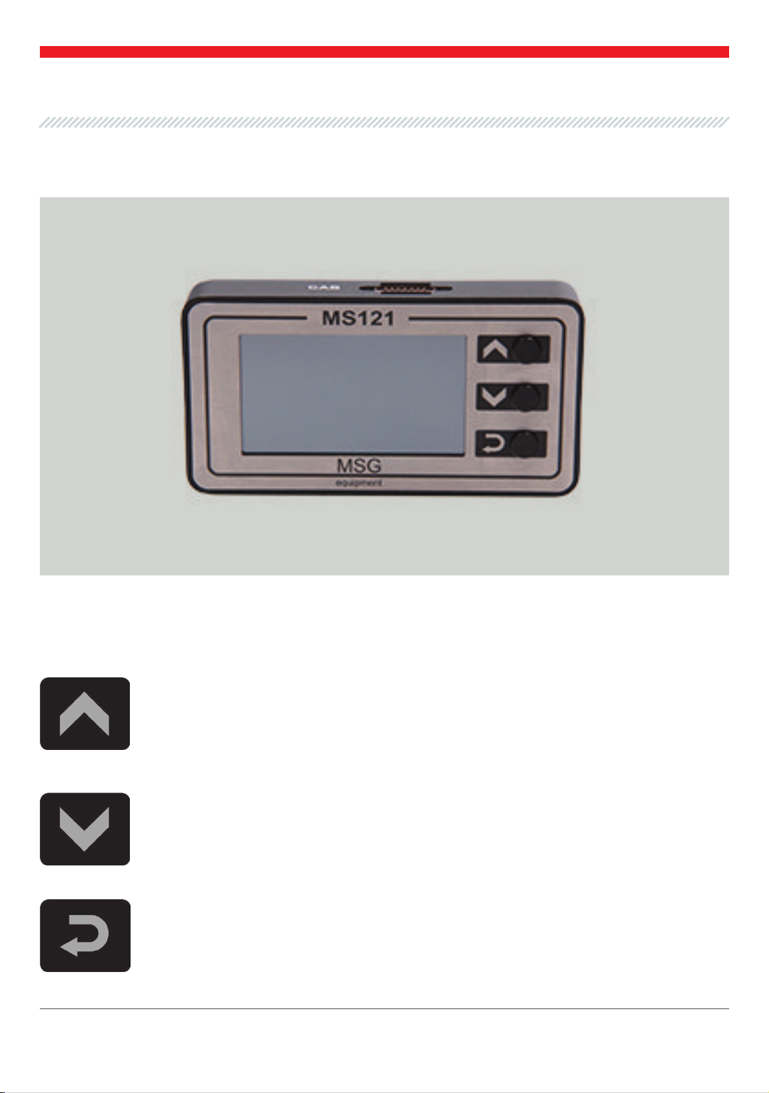
Button "UP" - is used to increase electromagnetic valve performance of the AC
compressor. Short pressing increases the performance by 5%, long pressing increases
the performance to maximum value, which is 95%. The button is not used while the
clutch testing
Button "Down" - is used to decrease electromagnetic valve performance of the AC
compressor. Short pressing decreases the performance by 5%, long pressing decreases
the performance to maximum value, which is 20%. The button is not used while the
clutch testing.
Button "Enter" - is used to enter / exit the testing mode of electromagnetic valves and
clutches.
3.1 Buttons
Fig. 1 – Tester MS121. General view
3. CONTROL UNITS
6
User Manual – Tester MSG MS121
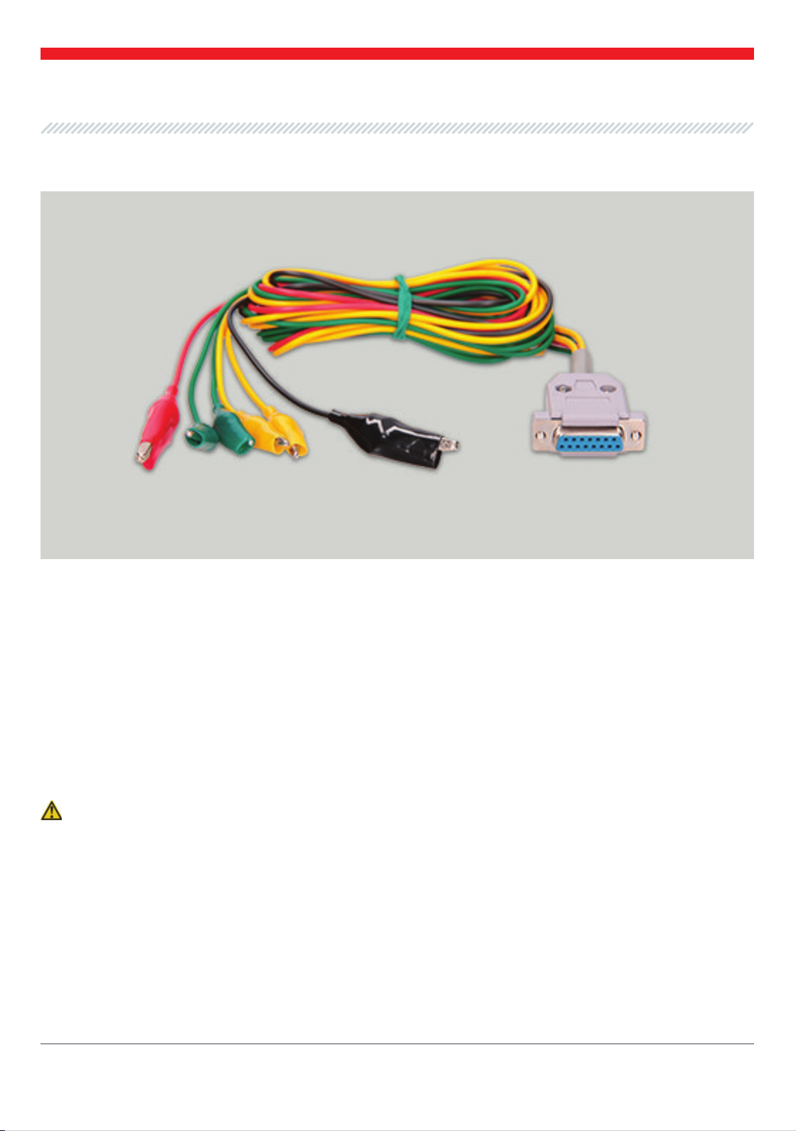
3.2 Terminals
The tester has a DA15 standard universal industrial socket to connect a diagnostic cable with the
following color marking:
• Yellow is used to connect the compressor electromagnetic valve;
• Green is used to connect the electromagnetic clutch;
• «-» (Black) «B-» is the battery negative pole (alternator housing);
• «+» (Red) «B +» is the battery positive pole, alternator output. It is used to power the device when
checking the valve / clutch on the test bench or on the vehicle, as well as for «B +» voltage
indication.
WARNING! It is recommended to use a battery with a nominal voltage of 12V or 24V as a power
supply source.
Fig. 1 – Tester MS121. General view
7
User Manual – Tester MSG MS121
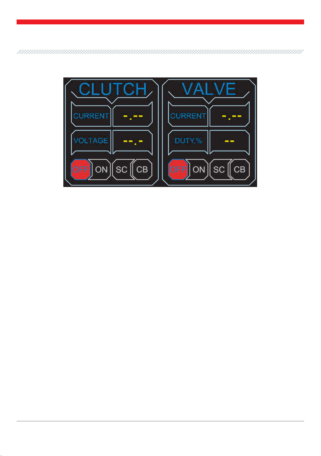
3.3 Menu
The tester menu has a user-friendly interface and is divided into two working areas:
"CLUTCH" is the area of the electromagnetic clutch testing result.
"VALVE" is the area of the electromagnetic valve testing result.
«CLUTCH» contains the following testing indicators:
«Current» – is the actual value of the current consumed by the electromagnetic clutch, A. Besides,
the current values, it can also contain the following indications:
«CB» (circuit break) – is the clutch circuit supply break. It may be caused by a break inside
the clutch winding.
«SC» (short circuit) – is the clutch short circuit. It may be caused by a turn-to-turn short
circuit of the clutch winding.
«Voltage» – is the actual value of the power supply (battery) voltage, V.
«VALVE» contains the following testing indicators:
«Current» – is the actual value of the current consumed by the electromagnetic valve, A. It may
change under different valve opening range.
«Duty, %» - the electromagnetic valve opening range in percent. Corresponds to the change in the
duty cycle of a pulse-width modulation (PWM) signal. This value is can be ranged from 20 to 95%.
Also, each of the testing areas contains indicators “CB” “SC”, their color indication corresponds to
a break or short circuit of the element under testing.
In some cases, if the 6A valve supply current is exceeded, the following indication may appear: —
in this situation it is recommended to turn off the device, reconnect to the valve under testing and
restart the valve testing mode.

User Manual – Tester MSG MS121
4. SETTING INTO OPERATION
Check the set received. It must contain:
•tester
•6-wire diagnostic cable with crocodile clips for testing the electromagnetic clutch / valve
•User Manual
Inspect the tester for existence of damage. If it is found, please contact either the manufacturer or
trade representative before launching the equipment.
WARNING! In case of obvious damage use of equipment is forbidden.
Connect the tester to a 12V power supply. If the connection is correct, the diagnostics menu will
appear on the tester screen.
Connect the electromagnetic clutch and / or valve to the corresponding connectors described in
paragraph 3.2. The polarity is not important while connection.
In the case when the valve or clutch is checked directly on the vehicle, and one of the
valve or clutch terminals is connected to the body of the car, an external battery must
be used to power the MS121.
5. STEP-BY-STEP INSTRUCTION
8

9
When the electromagnetic valve is faultless, the valve supply current will change, as wellas the
pressure in the HP and LP lines. The absence of these changes will signify the valve failure.
User Manual – Tester MSG MS121
Mind that some electromagnetic clutches may have a limiting diode in the construction
smoothing the voltage pulsation in the clutch supply circuit. If there is
a diode in the clutch under testing, the corresponding diode indicator will
appear on the tester display.It is also possible to test the clutch and valve
directly on the vehicle without removing the air conditioning com -
pressor. In this case the vehicle battery can be used to power the tester. For this type of testing it is
also recommended to use a device for measuring the refrigerant pressure in the air conditioning
system which is preliminary connected to the service outputs according to the diagram below:
The electromagnetic clutch is faultless under the following indicators:
•"Current" value should range between ХХ А up to YY А
•"Voltage" value should range between 10÷14V
•when "CB" or "SC" indication is absent on the screen
Press the testing start button

10
User Manual – Tester MSG MS121
To avoid possible electric shock or injury, or to avoid damage to the tester or the compressor
components under testing, adhere to the following rules strictly:
•Make sure that the diagnostic wires do not break or damage the insulation. To check the wires
for a break, it is enough to connect them (observing the color marking) to each other and switch
on the testing mode. If the diagnostic wires work correctly, the tester display in both zones will
show «SC» indication.
•When connecting the tester to the power supply, remember that the black wire is connected to
the negative pole and the red wire is connected to the positive pole.
•The power supply nominal voltage should be 12V ± 2V.
•Do not store or use the device in places with high temperatures, humidity, danger of explo- sion
or re, strong magnetic eld. As a result of high humidity impact, the tester performance may
deteriorate.
•Do not make self-willed changes to the tester electrical circuit. In case of a malfunction of the
tester, please contact the trade representative or directly MSG Equipment support.
•To clean the surface of the tester, use a soft cloth and spray to clean the screen. To avoid
corrosion, breakage or damage to the device, use of abrasives and solvents is strictl y for- bidden.
6. SAFETY MEASURES WHILE OPERATION
Other manuals for MS121
1
Table of contents
Languages:
Other MSG Equipment Test Equipment manuals

MSG Equipment
MSG Equipment MS016 User manual

MSG Equipment
MSG Equipment MS005 User manual

MSG Equipment
MSG Equipment MS021 User manual

MSG Equipment
MSG Equipment MS1000+ User manual

MSG Equipment
MSG Equipment MS603N User manual

MSG Equipment
MSG Equipment MS800 User manual

MSG Equipment
MSG Equipment MS1000+ User manual

MSG Equipment
MSG Equipment MS002 COM User manual

MSG Equipment
MSG Equipment MS031 User manual

MSG Equipment
MSG Equipment MS112 User manual


