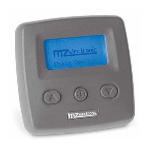
MZ electronic EV-040 User manual

Istruzioni per l’uso
Instructions for use
Instructions d'utilisation
Gebrauchsanweisung
Instrucciones de uso
RADIO CONTAMETRI
RADIO CHAIN COUNTER
RADIO CO PTEUR ÉTRIQUE
RADIO ETERZÄHLER
RADIO CUENTA ETROS
EV-040
Rev. 10 – 2014

Part. C
Part. A
magnetic sensor
sensore magnetico
Fig. 2A Fig. 2
Fig. 2C
sensor cable
cavo sensore
Fig. 1A
magnetic sensor
sensore magnetico
G2
G1
Part. B
Part. A
sensor cable
cavo sensore
magnet
Fig. 1
magnete
min.44 mm(1”3/4

EV-040 Rev. 10 – 2014
English
16
Description
The EV-040 radio-chaincounter displays the length of chain let out or down, expressed in metres or feet
and the speed of the same.
echnical data
Receiver
Power supply from 10 to 30 V DC
No-load current intake max 50 mA
Protection rating IP67
Operative temperature 0 / +70 °C (32 / 158 °F
Size (mm 150 x 110 x 75
Weight (g 350
Transmitter
Rechargeable lithium-ion battery
Duration in continuous duty 120 minutes
Graphic display 128 x 64 pixel
Operative temperature 0 / +70 °C (32 / 158 °F
Max. chain length 999 metres – 999 feet
Size (mm 145 x 50 x 20
Weight (g 100
Warning
CONNECT ONLY TO A DC POWER SUPPLY.
General notes
The EV-040 radio-chaincounter must be used solely for the purposes described herein, i.e. to operate and
display the number of metres/feet of chain let out by an anchor windlass. Any other use is to be
considered improper.
Any tampering with the instrument will result in immediate voiding of the warranty.
Components
The package contains:
• radio-chaincounter with rechargeable lithium-ion battery;
• fastening kit for radio-chaincounter (1 bracket with 2 screws ;
• power adaptor for lithium-ion battery charging;
• transmitter-receiver power unit;
• instructions for use.

EV-040 Rev. 10 – 2014
English
17
Installation
On a few models of anchor windlass the sensor and the magnet are already installed (chain
counter setting). Therefore, the operations described below are not necessary.
Installing the magnet on the anchor windlass
• A hole having a diameter of 6.5 mm (~1/4” and depth of 8 mm (5/16” must be drilled on a tooth
of the gipsy, in a place outside the chain’s path.
• In the case of vertical shaft anchor windlasses (see Fig. 1B , drill the hole in the lower
circumference of the gipsy.
• In the case of horizontal shaft anchor windlasses (see Fig. 2B , drill the hole in the outer
circumference of the gipsy.
• Also make sure that the protruding part of the magnet will not collide with the base or sensor
during rotation of the gipsy.
• Insert the metal part of the magnet in the hole, allowing the protected part to protrude by about 2
mm. Fix it in place using an adhesive for metals (two-component epoxy glue or silicone. The
glue used must be able to withstand a marine environment.
Installing the magnetic sensor for vertical shaft anchor windlasses
(see Fig. 1A – 1
• Drill a 4 mm (~3/16” hole in the cover through which to thread the
sensor cable.
• Fasten Part A of the support with the two screws provided, after
having positioned the O-ring in the lower part of the support.
• Fit Part B with the magnetic sensor on support A and adjust its
height until it is aligned with the magnet fastened on the gipsy.
• Bring the sensor to a distance of about 3 mm (~1/8” from the
magnet and secure it in place by tightening screw G1. Then tighten
screw G2.
Installing the magnetic sensor for horizontal shaft anchor
windlasses
(see Fig. 2A – 2 – 2C
• Drill a 4 mm (~3/16” hole in the cover through which to thread the
sensor cable.
• Fasten Part A of the support with the two screws provided, after having
positioned the O-ring in the lower part of the support.
• Cut Part C to measure using a hacksaw. The sensor must be positioned at a
distance of about 3 mm (~1/8” from the magnet.
• Fit Part C with the magnetic sensor on support A and fix it in place using an
adhesive for plastic (two-component epoxy glue or silicone.
• Using the same glue, attach the sensor to Part C.
C
A
OR
OR
A
G1
G2

EV-040 Rev. 10 – 2014
English
18
Installing the chain counter
(see connection diagram
Warning
ALWAYS DISCONNECT THE ATTERY PRIOR TO INSTALLATION.
• The chain counter must be positioned so that the display will be easy to read. It should not be
exposed to direct sunlight.
• Secure the instrument in place with the bracket provided, tightening the two screws using a
cross screwdriver.
• For instructions on making electrical connections, see the attached diagram. The wires must
have a minimum cross section size of 1.5 mm².
• Install a 3 A (ampere fast safety fuse on the + wire of the battery. Do not use the voltage
generated by the engine battery set to provide power.
• The instrument complies with EMC standards (EN55022 and must be positioned at a distance
of:
− 30 cm (~1 Ft from the compass;
− 50 cm (~1.5 Ft from radio equipment;
− 2 metres (~6.5 Ft from radio transmitter equipment;
− 2 metres (~6.5 Ft from the radar beam.

EV-040 Rev. 10 – 2014
English
19
Connections
6-POLE CONNECTOR
PIN SIGNAL
1 + battery
2 - battery
3 DOWN command
4 UP command
5 Magnetic sensor
6
Sensor hole
min.44 mm(1”3/4
4magnetic sensor
sensore magnetico
Recharging the transmitter
• Open the cap on the rear of the transmitter, insert the plug of the battery charger making sure
that the reference mark is facing upward. Plug the battery charger into a cigarette lighter to start
charging.
• When the charger is switched on the blue LED will light up.

EV-040 Rev. 10 – 2014
English
20
Starting up
The chain counter features a graphic display and three keys: (ON , (UP and
(DOWN .
The ON key switches on the display and enables the other two keys. It must be used to
access the parameter setting menus. For selecting the parameters to be modified and to
confirm the values set. The instrument will switch off 30 seconds after the last command
given (adjustable default time – see “Turnoff Time” .
The UP key commands the hoisting of the anchor and the DOWN key casts it. When
the key is released, the action is stopped. During parameter setting, the two keys allow
the User to move around the menu and vary parameter values.
When switched on, the following page will appear for a few seconds:
then the instrument will scan 5 frequencies within the 868 – 870 MHz band. During this phase the display
will show:
Searching...
when the instrument has identified the most suitable frequency it will connect to the power unit. The
address of the power unit will be shown on the display as follows:
Connecting
to ID :
00001
if communication is successfully established the following page will appear:
Connection
established
on channel :1
Once the initialisation procedure is complete, the main page will appear.
Stop
0.0ft
0.0 ft/m
STATUS
SPEED'
ICONS
COUNT
MONITORING
metres / feet
feet / minute
metres / minute
V=11.6 [1]
Where:
STATUS: indicates the status of the instrument and any failure.
SPEED’: indicates the chain speed during hoisting or lowering in meters per minute or feet per minute.
COUNT: indicates the measurement of the chain lowered (in metres or feet .
MONITORING: the bottom bar indicates the voltage of the boat battery, the power used for transmission
(minimum= 1, medium= 2, maximum= 3 and the charge status of the instrument’s lithium-ion battery.
ICONS: this is the part of the display bearing the icons that indicate the hoisting or casting of the anchor
and any failure.
When the instrument is turned on for the first time, it will set up as programmed in the factory (see table .

EV-040 Rev. 10 – 2014
English
21
Parameter Default value
Up Alarm 3.0 metres
Auto Down Off
Turnoff Time 30 seconds
Units of measurement Metres/centimetres
Chain Measure 0.0 metres
Barbotin Circumference 33 cm
Sensor type unknown
Language Italian
Works Hours 0
Division factor 1
Chain counter setting menu
Hold down the (ON key for six seconds
to access the instrument setting menu. The
following page will appear on the display:
Menu
M e a s u r e
A l a r m s & F u n c t i o n
S e t t i n g s
Language
S e n s o r C a l i b r a t i o n
Use the (DOWN and (UP keys to
move around the menu options.
Menu
Language
S e n s o r C a l i b r a t i o n
Te s t s
E x i t
Once you are positioned on the item to be modified press the (ON key to confirm your
choice.
Use the (DOWN or (UP keys to move from one parameter to another.
Once one is positioned on the parameter press the (ON key to enable modification.
According to the type of parameter, using the (DOWN and (UP keys it is possible to
reduce/increase the value of the same or disable/enable the function.
Once the modification has been performed, press the (ON key to confirm.
Using the (DOWN key go to the Exit option and press the (ON key again to return to
the setting menu. The same procedure must be used to return to the main page.

EV-040 Rev. 10 – 2014
English
22
Measurement menu
Use the (DOWN or (UP key to move around the parameters.
Reset Measurement
Resets the chain measurement value (0.0 . Select with
= Yes = No
Confirm with
Units
Selects the unit of measurement:
Feet/ inches
Metres / centimetres
Select with
= Feet = Metres
Confirm with
Exit
To return to the settings menu. Confirm with
Alarm and functions menu
Alarms & Functi
U p A l a r m 3 . 0
A u t o D o w n O f f
L o a d D e f a u l t N o
E x i t
Use the (DOWN or (UP key to move around the parameters.
Up Alarm
It is possible to enable the function and
establish the height at which the anchor-
winch stops; after which it is only possible to
give pulsed commands.
Settable values: 1.0 - 1.5 - 2.0…5.0 (metres
or feet .
Select with
Select value with
Confirm with
Auto Down
Enables the automatic anchor lowering
procedure, at the desired height, with the
pressing (for at least 3 seconds of the keys
and .
Settable value: 5 - 10 - 15…40 (metres or
feet .
Select with
Select value with
Confirm with
Load Default Select with

EV-040 Rev. 10 – 2014
English
23
This function allows the User to revert to the
original factory default settings, thus erasing
all settings memorised.
This command must only be used in the
event of programming errors.
= Yes = No
Confirm with
Exit
To return to the settings menu. Confirm with
Settings menu
Settings
C o n t r a s t
L i g h t
Tu r n o f f Ti m e 3 0
E x i t
Use the (DOWN or (UP key to move around the parameters.
Contrast
By enabling this function it is possible to start
the display contrast programming procedure.
Select with
Select value with
Confirm with
Light
By enabling this function it is possible to start
the display luminous intensity programming
procedure.
Select with
Select value with
Confirm with
Turnoff Time
This function allows the user to set the turnoff
time after the last command given (default
value 30 seconds .
Select with
Select value with
Confirm with
Exit
To return to the settings menu. Confirm with

EV-040 Rev. 10 – 2014
English
24
Language menu
Language
Language E n g l i s h
E x i t
Use the (DOWN or (UP key to move around the parameters.
Language
The user may select the display language:
Italian, English, French, German, Spanish
Select with
Select value with
Confirm with
Exit
To return to the settings menu. Confirm with
Sensor calibration menu
Sensor Calibrat
S e n s o r D e t e c t .
Barb. Circ. 3 3 . 0
E x i t
Use the (DOWN or (UP key to move around the parameters.
Sensor Detect
This function has the purpose of calibrating
the instrument according to the type of
sensor installed (Standard or Project .
The second screen indicates the time for a
sensor period and type.
Select with
Sensor Detect.
P r e s s U p / D o w n K e y
t o r u n t h e m o t o r
Press or
Sensor Detect
P r e s s U p / D o w n K e y
t o r u n t h e m o t o r
0 . 4 0 0 s e c .
S e n so r : S td
Sensor Detect
P r e s s U p / D o w n K e y
t o r u n t h e m o t o r
0 . 4 0 0 s e c .
S e n s o r : P r o j .
Confirm with
Once the “Sensor Detection” function has recognised a “Standard” type sensor instead of a
“Project” sensor, when the “Sensor Calibrat.” menu is entered again, the menu options will
“configure” themselves according to the sensor detected.

EV-040 Rev. 10 – 2014
English
25
Standard and X.. Project series
sensor menu
(magnet and sensor placed
on barbotin)
Sensor Calibrat
Barb. Circ. 3 3 . 0
D i v i s o r f a c t . 1
E x i t
1000 – 1500 –2000 W Project series
sensor menu
(magnet and sensor placed
on motor)
Sensor Calibrat
Red. Factor 5 7 . 0
E x i t
arbotin Circumference
In this row the user must enter the
circumference of the gipsy (in centimetres or
inches . Use the Table 1 provided to
calculate the circumference.
Settable values: centimetres or inches.
Default value, 33 cm.
Division Factor
If you use the 3-wire inductive sensor set
here the number of signatures of the gypsy
obtained from Table 1.
If you use the 2-wire magnetic sensor leave
the value set to 1.
Reduction Factor
In this row the user must enter the reduction
factor. See next Table 2 for the correct value
to be entered
Default value, 57.
Select with Select value with Confirm with
Exit
To return to the settings menu. Confirm with
able 1 - Standard and Project X.. series sensor
(magnet and sensor placed on barbotin)
Chain Type Number of recesses Gipsy Circumference
(cm
Gipsy Circumference
(inches
6 22 9
6 mm 9 34 13
7 mm 6 25 10
5 24 9
6 28 11
7 33* 13
8 mm
8 38 15
5 31 12
10 mm 6 36 14
5 36 14
12 mm 6 43 17
13 mm 6 46 18
14 mm 5 42 16
* factory settings of instrument

EV-040 Rev. 10 – 2014
English
26
able 2 - 1000 – 1500 – 2000W Project series sensor
(magnet and sensor placed on motor)
Check menu
Tests
LCD Test
S w . Ve r s i o n 1 . 0 1
W o r k H o u r s 0
E x i t
Use the (DOWN or (UP key to move around the parameters.
LCD Test
This function switches on all the display’s
pixels thus making it possible to perform a
check on them.
Select with
Confirm with
Software Version
Indicates the version of the software installed.
Work Hours
Indicates the hours of operation of the winch.
Exit
To return to the settings menu. Confirm with
Type Gipsy
Circumfer. (cm
Reduction
ratio
Number of
recesses
Chain type
(mm-inches
Reduction
Factor
30 1:52 6 8-5/16”HT
30 1:52 5 10 DIN 766 57*
31 1:52 5 10 ISO-3/8”HT 59
Project 1000
34 1:52 9 6 65
30 1:70 6 8-5/16”HT 43
30 1:70 5 10 DIN 766 43
31 1:70 5 10 ISO-3/8”HT 44
Project 1500
36 1:70 5 12 ISO-13 DIN 766-7/16”HT
51
39 1:75 6 3/8”HT 52
40 1:75 6 3/8”Proof Coil 53
41 1:75 6 10 DIN 766-3/8”BBB 54
44 1:75 7 10 ISO 58
45 1:75 5 14 ISO 60
46 1:75 6 12 ISO-13 DIN 766 61
Project 2000
47 1:75 5 13 DIN 764 63
* factory setting of instrument

EV-040 Rev. 10 – 2014
English
27
Instrument calibration
Before using the instrument the following parameters must be set:
• choice of unit of measurement (metres or feet ;
• detection of type of sensor (Standard or Project ;
• gipsy diameter setting (default value 33 cm or reduction factor (default value 57 ;
Standard and X.. Project series
sensor menu
Sensor Calibrat
Barb. Circ. 3 3 . 0
D i v i s o r f a c t . 1
E x i t
1000 – 1500 –2000 W Project series sensor
menu
Sensor Calibrat
Red. Factor 5 7 . 0
E x i t
Use
Press the (ON key to activate controls and to switch on the display lighting. The display lighting
switches off 30 seconds after the last command given (adjustable default time – see “BkLight Time” .
Press key (UP) to control the anchor ascending.
Chain Up
4.0 ft/m
21.0
ft
V=11.6 [1]
Press key (DOWN) to cast anchor.
Chain Down
6.0 ft/m
10.0
ft
V=11.6 [1]
When any key is released (UP or DOWN) the corresponding action is stopped.
Measurement reset
To reset the measurement count simultaneously press the (ON and the (UP keys for at least
three seconds.
Measurement reset may also be performed in the Measurement menu by selecting “Yes” in the Reset
Measure row.
Automatic casting of the anchor
This function must be enabled in the Alarms and Functions menu (disabled by default .
Alarms & Functi
U p A l a r m 3 . 0
A u t o D o w n O f f
L o a d D e f a u l t N o
E x i t
Select the row “Auto Down” and set the value at which the anchor must stop. Then press the (ON
and (DOWN keys for at least three seconds. Once anchor casting has commenced, release the keys.
For safety reasons it is however possible to interrupt automatic descent by pressing any
instrument key.

EV-040 Rev. 10 – 2014
English
28
roubleshooting
FAULT CAUSE CORRECTIVE ACTION
No Sensor
0.0 ft/m
0.0
ft
V=11.6 [1]
Though UP or DOWN keys
are pressed, the instrument
doesn't receive any signal
from the magnetic sensor
for more than 5 seconds.
Check the sensor electric
connections.
Check if sensor operates
properly. If not, replace it.
Check the position of
sensor and magnet on
gipsy and their distance (3
mm .
Check the operation of
electric installation or
anchor windlass.
Low Voltage
0.0 ft/m
0.0
ft
V=7.9 [1]
The instrument’s power
supply voltage is lower than
10V.
Verify the charge of the
boat’s battery or operation
of the electrics system.
Stop
0.0
ft
0.0 ft/m
V=11.6 [1]
The instrument’s lithium-ion
battery is discharged.
Recharge the instrument
using the power adaptor
supplied.
While the battery is
charging the red LED of the
adaptor will remain lit.
When the LED goes off it
means the battery is fully
recharged.

MZ ELECTRONIC S.R.L.
www.mzelectronic.com
e-mail:info@mzelectronic.com
Other manuals for EV-040
1
Table of contents
Other MZ electronic Cash Counter manuals

MZ electronic
MZ electronic EV030-Radio User manual

MZ electronic
MZ electronic WHC040 User manual

MZ electronic
MZ electronic EV-011 User manual

MZ electronic
MZ electronic HC020 User manual

MZ electronic
MZ electronic EV-030 User manual

MZ electronic
MZ electronic EV-020 User manual

MZ electronic
MZ electronic EV-030 User manual

MZ electronic
MZ electronic EV-020 User manual

MZ electronic
MZ electronic EV-040 User manual

MZ electronic
MZ electronic EV-020 User manual