Nautel Vector-LP VR125 Owner's manual

Vector-LP
Radio Beacon
Transmitter
Technical Instruction Manual
VR125
VR250
Issue 1.1 .................... 24 February 2009
Nautel Limited
10089 Peggy's Cove Road,
Hackett's Cove, NS, Canada B3Z 3J4
T.877 6 nautel (628835) or +1.902.823.2233
U.S. customers please contact:
Nautel Inc.
201 Target Industrial Circle, Bangor ME 04401
T.877 6 nautel (628835) or +1.207.947.8200
www.nautel.com
Copyright 2009 NAUTEL. All rights reserved.


Vector-LP Radio Beacon Transmitter Technical Instruction Manual Feb.24.09
Warranty
by Nautel Limited/Nautel Inc. (herein after referred to as Nautel)
Nautel Limited/Nautel Incorporated, hereinafter referred to as Nautel, guarantees all mechanical and electrical parts of
the equipment for a period of thirteen months from date of shipment.
1. A "Part Failure" shall be deemed to have occurred when the part has become defective, or does not have the
characteristics required for the specified equipment performance:
(a) When the equipment is operated within the design parameters, and
(b) When the equipment is installed and adjusted according to Nautel's prescribed procedures as stated in
the instruction manual.
2. Nautel shall provide replacements for all "Parts" at no cost to the Customer when they become defective during
the warranty period, and upon the return of the defective part.
3. In the event that a "Part" fails during the warranty period and causes damage to a sub-assembly that cannot be
readily repaired in the field, the entire sub-assembly so damaged may be returned to Nautel for repair. The
repairs will be made without charge to the Customer.
4. Where warranty replacements or repair are provided under items 2 or 3, Nautel will pay that part of the shipping
costs incurred in returning the part/assembly to the Customer.
5. Warranty replacement parts and repair, which are provided under items 2 or 3, shall be guaranteed for a period
of ninety days from date of shipment or until the end of the original warranty period, whichever occurs later.
6. Nautel will not assume responsibility for any charges incurred by other than Nautel employees.
7. Nautel shall have the privilege of investigating whether failures have been caused by factors beyond its control.
8. Nautel shall in no event be liable for any consequential damages arising from the use of this equipment.
9. When requesting a warranty repair/replacement, please provide complete and accurate information. Observe
the instructions regarding 'Equipment Being Returned to Nautel' on page two of this warranty and provide the
information requested.
10. When ordering spare/replacement parts, please provide complete and accurate information. Refer to the parts
list of the Repair manual for ordering information. Provide as much of the information requested for 'Equipment
Being Returned to Nautel' on page two of this warranty as is practical. The information identified by an asterisk
is the minimum required.
Nautel Limited Nautel Inc.
10089 Peggy's Cove Road 201 Target Industrial Circle
Hackett's Cove NS Canada B3Z 3J4 Bangor ME USA 04401
T. 877 6 nautel (628835) or 1.902.823.2233 T. 877 6 nautel (628835) or 1.207.947.8200
F. 1.902.823.3183 F. 1.207.947.3693
24hr. Answering Service 1.902.823.3900
Customer Service Notice
A ‘Technical Assistance’ and ‘Plug-in Module Exchange’ service is available to Nautel users.

Vector-LP Radio Beacon Transmitter Technical Instruction Manual Feb.24.09
Factory Support
TECHNICAL ASSISTANCE
Nautel's field service department provides telephone technical assistance on a 24 hour, seven days a week basis.
Requests by other media (facsimile or e-mail) will be responded to the next working day if received after Nautel's normal
working hours. Contact the appropriate field service centre from the following:
U.S.A. customers use: Nautel Incorporated T. +1.207.947.8200 (24 hours) or 877 6 nautel (628835)
201 Target Industrial Circle F. +1.207.947.3693
Bangor, Maine 04401
All other customers use: Nautel Limited T. +1.902.823.3900 (24 hours) or 877 6 nautel (628835)
10089 Peggy’s Cove Road, F. +1.902.823.3183
Hackett’s Cove, NS, Canada E-Mail support@nautel.com
B3Z 3J4 Web www.nautel.com
MODULE EXCHANGE SERVICE
In order to provide Nautel customers with a fast and efficient service in the event of a problem, Nautel operates a
factory rebuilt, module exchange service which takes full advantage of the high degree of module redundancy in
Nautel equipment. This module exchange service is operated from Nautel’s factory in Bangor, Maine and Hackett’s
Cove, Nova Scotia. These two locations allow us to provide a quick turn around service to keep our customers on
the air. During the transmitter’s warranty period, up to thirteen months from shipment, repair and exchange of
modules is at no charge to the customer. When the warranty has expired, a charge of 80% of the list price for all
exchanged modules is made. If the faulty module is returned to Nautel within 30 days, a credit is issued reducing
this charge by one half to 40% of the list price. U.S.A. customers are required to contact our Bangor, Maine facility.
Canadian and overseas customers should contact our Nova Scotia, Canada facility.
EQUIPMENT BEING RETURNED TO NAUTEL
For all equipment being returned to Nautel and all requests for repairs or replacements:
Obtain an RMA number from Nautel (you must have an RMA number to return equipment)
Mark the item as 'field return'
Mark the item with the RMA number assigned by Nautel
Address the item to the appropriate Nautel facility
Complete and accurate information regarding the equipment being returned will ensure prompt attention and will
expedite the dispatch of replacements. Refer to the nameplate on the transmitter and/or the appropriate
module/assembly to obtain name, type, part and serial number information. Refer to the parts list of this manual or the
appropriate service instruction manual for additional ordering information.
The following information should accompany each request:
* Model of Equipment
* Serial number of Equipment
* Name of Part/Assembly
Serial number of Part/Assembly
* Complete reference designation of Part/Assembly
* Nautel's part number of Part/Assembly
* OEM's part number of Part/Assembly
Number of hours in Use
Nature of defect
* Return shipping address
* Denotes minimum information required to order spare/replacement parts
Vector-LP Radio Beacon Transmitter Technical Instruction Manual Feb.24.09
Safety
Symbols
General definitions of safety symbols used on equipment or in manuals.
DANGER – HIGH VOLTAGE
Indicates dangerous voltages (in excess of 72 V), capable of causing a fatal
electrical shock, are present on or near parts bearing this label.
GROUND (EARTH)
Used with wiring terminals to indicate the terminal must be connected to
earth ground before operating equipment. If power is supplied without
grounding the equipment, there is a risk of receiving a severe or fatal
electrical shock. Also used on electrical schematics to indicate a part that is
connected to earth ground.
GROUND (PROTECTIVE or SAFETY)
Used with protective (safety) conductor terminals to indicate the terminal
must be connected to ground before operating the equipment. If power is
supplied without grounding the equipment, there is a risk of receiving a
severe or fatal electrical shock.
ELECTROSTATIC SENSITIVE
Indicates a part or assembly is or contains devices that are electrostatic
sensitive. To prevent damage to these devices, ensure the handling
procedures outlined in this manual are observed.
WARNING A WARNING denotes a hazard. It identifies an operating procedure,
condition, etc. which, if not strictly observed or adhered to, could result in
injury or death to personnel. Throughout the technical manual, a
WARNING shall immediately precede the text to which it applies.
CAUTION A CAUTION denotes a hazard. It identifies an operating procedure,
condition, etc., which, if not strictly observed or adhered to, could result in
damage to, or destruction of the equipment. Throughout the technical
manual, a CAUTION shall immediately precede the text to which it
applies.
NOTE A NOTE denotes important information pertaining to an operating
procedure, condition, statement, etc., which is essential to highlight. A
NOTE may precede or follow the text to which it applies.

Vector-LP Radio Beacon Transmitter Technical Instruction Manual Feb.24.09
Safety
Toxic Hazard Warning
There are devices used in this equipment containing beryllium oxide ceramic,
which is non-hazardous during normal device operation and under normal device
failure conditions. These devices are specifically identified in the equipment parts
list(s) by including ‘BeO’ in the part’s description.
DO NOT cut, crush or grind devices because the resulting dust may be
HAZARDOUS IF INHALED. Unserviceable devices should be disposed of as
harmful waste.

Vector-LP Radio Beacon Transmitter Technical Instruction Manual Feb.24.09
Declaration of Conformity
Hereby, Nautel Ltd. declares that this Non-Directional Radio Beacon
Transmitter Vector, NDB 125/250, is in compliance with the essential
requirements and other relevant provisions of Directive 1999/5/EC.
This subject equipment is intended for use in the following Member
States:
Ireland
United Kingdom
The original Declaration of Conformity may be found on the Nautel Web
site:
www.nautel.com


Vector-LP Radio Beacon Transmitter Technical Instruction Manual Feb.24.09
Contents Page
1 GENERAL INFORMATION
1.1 INTRODUCTION 1-1
1.2 FACTORY SUPPORT 1-1
1.3 PURPOSE AND SCOPE OF MANUAL 1-1
1.4 PURPOSE OF EQUIPMENT 1-1
1.5 MECHANICAL DESCRIPTION 1-2
1.6 TEST EQUIPMENT AND SPECIAL TOOLS 1-2
1.7 GLOSSARY OF TERMS 1-2
2 PREPARATION FOR USE AND INSTALLATION
2.1 INTRODUCTION 2-1
2.2 PREPARATION FOR USE 2-1
2.2.1 Transmitter Room Requirements 2-1
2.2.1.1 Transmitter Dimensions 2-1
2.2.1.2 Transmitter Weights 2-1
2.2.1.3 Transmitter Clearances 2-1
2.2.1.4 Air Flushing 2-1
2.2.1.5 Cooling and Heating 2-1
2.2.1.6 Work Area 2-1
2.2.1.7 Power Source Switch 2-1
2.2.2 Lightning Protection 2-2
2.2.3 Station Reference Ground 2-2
2.2.4 Ac Power Source 2-2
2.2.4.1 Ac Wiring 2-2
2.2.5 Antenna Feed Cable 2-7
2.2.6 Antenna Tower 2-7
2.2.7 External Control/Monitor Wiring 2-7
2.2.8 Electrical Power 2-7
2.2.8.1 Ac Voltage Source 2-7
2.2.8.2 External Ac Switching 2-7
2.2.8.3 Dc Voltage Source 2-7
2.2.9 Antenna System 2-8
2.2.9.1 RF Feed Cable 2-8
2.2.9.2 Interface Protection Option 2-8
2.2.10 Internal DDS Source 2-8
2.2.11 External Interlocks 2-9
2.2.12 Remote Control Circuits 2-9
2.2.12.1 On/Off Control 2-10
2.2.12.2 Charger Alarm 2-10
2.2.12.3 Standby Code 1 2-10
2.2.12.4 Standby Code 2 2-10
2.2.13 Press-To-Talk Input 2-10
2.2.14 User Assigned Information 2-10
2.2.14.1 Carrier Frequency 2-10
2.2.14.2 Keyed Tone Frequency 2-10

Vector-LP Radio Beacon Transmitter Technical Instruction Manual Feb.24.09
Contents Page
2.2.14.3 Identification Code 2-10
2.2.14.4 Standby Codes 2-10
2.2.15 Serial Port Features 2-11
2.2.15.1 Remote Control and Monitoring Interface 2-11
2.2.15.2 ATU Interface 2-11
2.2.16 RF Monitoring Sample 2-11
2.2.17 Parts Supplied By Nautel 2-11
2.2.18 Parts Not Supplied By Nautel 2-11
2.2.19 Test Equipment and Special Tools 2-11
2.2.20 Available Options 2-11
2.3 INSTALLATION 2-13
2.3.1 Acceptance of Shipment 2-13
2.3.2 Unpacking Instructions 2-13
2.3.3 Visual Inspection 2-13
2.3.4 Cabinet Mounting 2-14
2.3.5 Determining Control/Monitor Requirements 2-14
2.3.6 Installing External Control/Monitor Wiring 2-14
2.3.7 Installing Ac Power Source Wiring 2-15
2.3.8 Installing Dc Power Source Wiring (Optional) 2-15
2.4 COMMISSIONING 2-17
2.4.1 Precautions 2-17
2.4.2 Turn-On Prerequisites 2-17
2.4.3 Initial Turn-On 2-17
3 OPERATING INSTRUCTIONS
3.1 INTRODUCTION 3-1
3.1.1 Precautions 3-1
3.2 EMERGENCY SHUTDOWN 3-1
3.2.1 Turn Off RF Output 3-1
3.2.2 Complete Shutdown 3-1
3.3 EXTERNAL SAFETY INTERLOCK 3-1
3.4 ELECTROSTATIC DISCHARGE PROTECTION 3-2
3.5 CONTROLS AND INDICATORS 3-2
3.5.1 Front Panel 3-3
3.5.2 Exciter Interface PWB 3-4
3.5.3 Remote Interface PWB 3-4
3.5.4 RF Synthesizer PWB 3-4
3.5.5 Miscellaneous Control and Exciter 3-4
3.5.6 Miscellaneous RF Power Stage 3-4
3.5.7 Battery Boost PWB 3-4
3.6 DIAGNOSTIC DISPLAY 3-18
3.6.1 Pushbutton Switches 3-18

Vector-LP Radio Beacon Transmitter Technical Instruction Manual Feb.24.09
Contents Page
3.6.2 Main Screens 3-18
3.6.3 Viewing Faults 3-20
3.6.4 Changeover Control 3-20
3.6.5 Viewing Events Log 3-20
3.6.6 Setting Real Time Clock 3-21
3.6.7 Setting RF Monitor Limits 3-22
3.6.8 Meter Settings 3-24
3.6.8.1 Changing Meter Groups 3-24
3.6.8.2 Selecting Analog Meter 3-25
3.6.8.3 Calibrating Analog Meter 3-25
3.6.9 Selecting Power Source 3-25
3.6.10 Configuring the Sonalert 3-26
3.6.11 Setting a Timed Shutdown 3-26
3.6.12 Changing Factory Calibrated Settings 3-27
3.6.12.1 Calibrating Diagnostic Display Meters 3-28
3.6.12.2 Setting Protection Threshold Levels 3-28
3.6.12.3 Setting Maximum Output Limitations 3-29
3.6.12.4 Using Factory Settings 3-29
3.6.13 Viewing and Setting Peripherals 3-30
3.6.13.1 Setting the Keyer 3-30
3.6.13.2 Viewing Power Module Status 3-31
3.6.13.3 ATU Controls 3-32
3.6.13.4 Testing the Standby Side 3-33
3.6.13.5 Selecting Peripherals 3-33
3.6.13.6 Checking Modules 3-34
3.6.14 Remote Control Monitor System Settings 3-34
3.6.14.1 Setting Control Points 3-34
3.6.14.2 Setting Monitor Points 3-35
3.6.14.3 Serial Settings 3-35
3.6.14.4 Automatic Reporting 3-35
3.6.15 Viewing Power Related Parameters and
Setting ATU Current Feedback 3-36
4 TESTING AND ADJUSTMENT
4.1 INTRODUCTION 4-1
4.2 OPERATING PRECAUTIONS 4-1
4.3 FUNCTIONAL TESTS 4-1
4.3.1 General 4-1
4.3.2 Test Equipment Required 4-3
4.3.3 Test Prerequisites 4-3
4.3.4 Initial Turn On 4-3
4.3.5 Standard Adjustments 4-4
4.3.6 Non-Standard Adjustments 4-8

Vector-LP Radio Beacon Transmitter Technical Instruction Manual Feb.24.09
Contents Page
5 MAINTENANCE AND TROUBLESHOOTING
5.1 GENERAL 5-1
5.2 SCHEDULED MAINTENANCE 5-1
5.3 CORRECTIVE MAINTENANCE 5-2
5.4 ELECTROSTATIC PROTECTION 5-2
5.5 TROUBLESHOOTING FRONT PANEL ALARMS 5-3
5.6 REPLACING AN RF POWER MODULE 5-9
5.7 FET CHECKING/REPLACEMENT 5-11
5.8 EXCITER PANEL PWB REPLACEMENT 5-12
5.8.1 Exciter Interface PWB and Interconnecting PWB
Replacement 5-12
5.8.2 Exciter Monitor/Generator PWB Replacement 5-13
5.8.3 Interface PWB Replacement 5-14
5.9 BATTERY BOOST ASSEMBLY REPLACEMENT 5-14
6 THEORY OF OPERATION
6.1 INTRODUCTION 6-1
6.2 TRANSMITTER OVERVIEW 6-1
6.3 AC_DC POWER STAGE 6-1
6.3.1 Interface PWB 6-5
6.3.2 Ac/Dc Universal Input Power Supplies 6-5
6.4 EXCITER STAGE 6-6
6.4.1 Exciter Interface PWB 6-6
6.4.2 RF Synthesizer PWBs 6-6
6.4.3 Interphase PDM Driver PWBs 6-8
6.4.4 Exciter Monitor/Generator PWBs 6-15
6.5 CONTROL/MONITOR STAGE 6-16
6.5.1 Control/Display PWB 6-16
6.5.2 Remote Interface PWB 6-19
6.5.3 Front Panel Metering 6-20
6.5.4 NDB Site Interface PWB (Optional) 6-21
6.5.5 Modem (Optional) 6-21
6.6 RF POWER STAGE 6-22
6.6.1 RF Power Module(s) 6-22
6.6.2 RF Filter PWB 6-29
6.6.3 RF Power Probe PWB 6-29
6.7 MODULATION DEPTH WHEN USING A HIGH ‘Q’
ANTENNA 6-30

Vector-LP Radio Beacon Transmitter Technical Instruction Manual Feb.24.09
Contents Page
7 PARTS INFORMATION
7.1 INTRODUCTION 7-1
7.2 FAMILY TREE 7-1
7.3 HOW TO LOCATE INFORMATION FOR A
SPECIFIC PART 7-1
7.4 REFERENCE DESIGNATION LISTS 7-1
7.5 COLUMN CONTENT EXPLANATION 7-1
7.6 OEM CODE TO MANUFACTURER CROSS-REFERENCE 7-2
7.7 COMMON ABBREVIATIONS/ACRONYMS 7-3
8 WIRING INFORMATION
8.1 INTRODUCTION 8-1
8.2 WIRING LISTS NOT PROVIDED 8-1
8.3 PRINTED WIRING PATTERNS 8-1
8.4 WIRE COLOURS 8-1
8.5 WIRING LISTS PROVIDED 8-1
8.5.1 Connector Mating Information 8-1
9 ELECTRICAL SCHEMATICS
9.1 INTRODUCTION 9-1
9.2 COMPONENT VALUES 9-1
9.3 GRAPHIC SYMBOLS 9-1
9.4 LOGIC SYMBOLS 9-1
9.5 REFERENCE DESIGNATIONS 9-1
9.6 UNIQUE SYMBOLOGY 9-1
9.7 TROUBLESHOOTING AIDS 9-1
9.8 IDENTIFICATION OF SCHEMATIC DIAGRAMS 9-2
9.9 STRUCTURE OF SCHEMATICS 9-2
9.10 LOCATING THE SCHEMATIC DIAGRAM(S) FOR A
FUNCTIONAL BLOCK 9-2
9.11 LOCATING A PART/ASSEMBLY IDENTIFIED
ON A SCHEMATIC 9-2
10 MECHANICAL DRAWINGS
10.1 INTRODUCTION 10-1
10.2 LOCATING ASSEMBLY DETAIL DRAWINGS 10-1
10.3 CONTENT OF MECHANICAL DRAWINGS 10-1

Vector-LP Radio Beacon Transmitter Technical Instruction Manual Feb.24.09
Contents Page
List of Tables
1-1 Dimensions and Weights 1-2
1-2 Recommended Site Test Equipment 1-3
1-3 Glossary of Terms 1-4
2-1 Ac Power Consumption 2-7
2-2 Dc Power Consumption 2-8
2-3 ATU Serial Interface 2-14
2-4 RS-422 Remote Interface 2-14
2-5 RS-232 Remote Interface 2-14
2-6 Dc Power Connection 2-15
2-7a RF Filter PWB Tap Settings vs Frequency (Standard Frequency Band)2-16
2-7b RF Filter PWB Tap Settings vs Frequency (Extended Frequency Band)2-16
3-1 Front Panel – System Diagram Controls and Indicators 3-5
3-2 Front Panel – Control Section Controls and Indicators 3-7
3-3 Exciter Interface PWB Controls and Indicators 3-9
3-4 Remote Interface PWB Controls and Indicators 3-11
3-5 RF Synthesizer PWB Controls and Indicators 3-13
3-6 Miscellaneous Control and Exciter Assembly Controls and Indicators 3-14
3-7 Miscellaneous RF Power Stage Controls and Indicators 3-15
3-8 Battery Boost PWB Controls and Indicators 3-17
3-9 Events Log Displays – Non Alarm Events 3-21
5-1 Troubleshooting and Replacement Tips 5-5
6-1 Battery Select Logic 6-5
7-1 Manufacturer’s Index 7-4
8-1 Wiring Lists Provided 8-1
9-1 Electrical Schematics 9-3
10-1 Mechanical Drawings 10-2

Vector-LP Radio Beacon Transmitter Technical Instruction Manual Feb.24.09
Contents Page
List of Figures/Drawings
2-1 Vector-LP Transmitter Environment Considerations 2-3
2-2 Customer Interface to Vector-LP Transmitter 2-5
2-3 Single Ended Input Selected 2-9
2-4 Differential Input Selected 2-10
2-5 Block Diagram – Recommended Transmitter System Installation 2-19
3-1 Vector-LP Transmitter Front Panel (Primary User Interface) 3-3
3-2 Vector-LP Transmitter Front Panel – System Diagram Section 3-4
3-3 Vector-LP Transmitter Front Panel – Control Section 3-6
3-4 Part of NAPI76A/02 Exciter Interface PWB A2 3-8
3-5 Part of NAPI78B/02 Remote Interface PWB A3 3-10
3-6 NAPE70C RF Synthesizer PWB A5 and A8 3-12
3-7 NAPS35 Battery Boost PWB A16A1 (Optional) 3-16
3-8 Diagnostic Display – Meters Screen 3-18
3-9 Diagnostic Display – Main Menu 3-18
3-10 Flow Diagram – Diagnostic Display Functions 3-19
4-1 Exciter Panel and Rear View 4-2
4-2 CW signal set to fill display 4-15
4-3 CW signal with position adjusted to mid-point of display 4-15
4-4 MCW signal, 95% modulation 4-15
5-1 RF Power Module Securing Hardware 5-10
6-1 Block Diagram - Vector-LP Radio Beacon Transmitter 6-3
6-2 Block Diagram – Exciter/Control/Monitor Stage 6-11
6-3 Timing Diagram for PDM Differential Amplifier 6-13
6-4 Block Diagram – RF Power Stage 6-25
6-5 Block Diagram – RF Power Module 6-27
6-6 Simplified Principles of Class ‘D’ Operation 6-31
7-1 Family Tree – Vector-LP Radio Beacon Transmitter 7-5


Vector-LP Radio Beacon Transmitter Technical Instruction Manual Feb.24.09
Release Control Record
Issue Date Reason
1.0 03 December 2007 Initial approved release of manual
1.1 24 February 2009 Added information for short cabinet option


Vector-LP Radio Beacon Transmitter Technical Instruction Manual Page 1-1
Section 1 General Information Issue 1.1
Vector-LP Radio Beacon Transmitter
TECHNICAL INSTRUCTION MANUAL
Section 1 GENERAL INFORMATION
1.1 INTRODUCTION
The Vector-LP radio beacon transmitter:
xAutomatically transmits specific
beacon identification signals at pre-
selected repetition rates. Special codes
may also be transmitted when
commanded from an external source.
Provision is made for local or remote
operation of the transmitter as well as
antenna fine-tuning through controls on
the transmitter's front panel. Emission
is continuous carrier (NON), beacon
keyed identification tone (A2A) and
beacon with voice (A2A/A3A).
xProvides continuous carrier power for
two different power configurations:
VR125 125 W maximum
VR250 250 W maximum
xCan be modulated from 0 to 95%.
xOperates in the LF/MF band (190 kHz
to 535 kHz).
xVR125 has provision for extended
band operation, up to 125 W, in the MF
band (536 kHz to 1200 kHz and
1600 kHz to 1800 kHz).
xHas provision for a standby exciter
section, which duplicates the PDM
and RF drive generation circuitry and
low voltage power supplies.
xHas provision for single side or dual
side (A and B) RF power sections,
which can be manually or
automatically selected.
xCan be serially connected to Nautel’s
ATU-LP or ATU500 Antenna Tuning
Unit, allowing a variety of control/
monitoring features, including
stabilization of the antenna current
(ATU-LP only) by automatically
adjusting transmitter power level.
1.2 FACTORY SUPPORT
Nautel provides after sales factory
support. Technical assistance is available
on a 24 hour, seven days a week basis. A
factory service facility for repair of
modules/assemblies is also available.
Refer to the Factory Support portion of the
Warranty pages at the front of this manual
for additional information.
1.3 PURPOSE AND SCOPE OF
MANUAL
This Technical Instruction manual
provides the information required to
install, operate and maintain the
equipment. Where applicable, changes
have been incorporated to reflect non-
standard customer requests.
1.4 PURPOSE OF EQUIPMENT
When combined with an appropriate
antenna system, the Vector-LP transmitter
provides reliable facilities for an NDB
reference station. It is ideally suited for
remote or unmanned sites. Remote control
facilities are incorporated to allow
unattended operation from a remote
location.

Page 1-2 Vector-LP Radio Beacon Transmitter Technical Instruction Manual
Issue 1.1 Section 1 General information
1.5 MECHANICAL DESCRIPTION
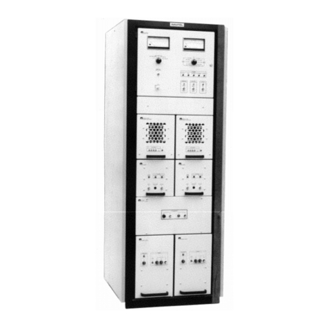
See Figure MD-1. The Vector-LP
transmitter is a fabricated metal chassis
with an attached full-depth front panel. It is
intended for installation in a 19-inch
mounting rack. It can be supplied with non-
swivel type drawer slides (including portion
attached to mounting rack).
Nautel provides three rack mounting
options (see Table 1-1 for dimensions and
weights).
- a deluxe cabinet that supports 19-inch
rack mount equipment, including side
panels, rear door, RF output
connector, ac line cord and optional
battery charger (see Figure MD-1B)
- a cabinet that meets IP66
requirements (see Figure MD-1C)
- a short cabinet that supports 19-inch
rack mount equipment, including side
panels, rear door, RF output
connector, ac line cord and optional
battery charger (see Figure MD-1D)
All external connections are made at the
back of the transmitter. The RF output
coaxial cable connects to an N-type
connector. The ac power cable connects to
a standard ac line connector. The dc power
cabling, if applicable, connects to a
terminal block. External input (RF drive and
control) and output (status and alarm
monitoring) connect to connectors on the
remote interface PWB. If the transmitter is
installed in the optional deluxe or short
cabinet, cable entry holes are provided. If
the transmitter is installed in the optional
IP66 cabinet, weather-proof cabinet
connectors are provided.
1.6 TEST EQUIPMENT AND
SPECIAL TOOLS
Table 1-2 lists the test equipment and
special tools that are required to operate
and maintain the Vector transmitter.
1.7 GLOSSARY OF TERMS
Table 1-3 provides a list of unique terms,
abbreviations, and acronyms used in this
publication.
Table 1-1: Dimensions and Weights
DIMENSIONS WEIGHT
VR125/VR250
(dual side installed) Height Width Depth Packed Unpacked
No cabinet 21.0 in.
(53.3 cm)
19.0 in.
(48.3 cm)
27 in.
(68.6 cm) TBD 54 lbs
(24.5 kg)
Deluxe cabinet 73.2 in.
(185.9 cm)
23.0 in.
(58.4 cm)
30.0 in.
(76.2 cm)
345 lbs
156.5 kg) TBD
Short cabinet 42 in.
(106.7 cm)
23.0 in.
(58.4 cm)
30 in.
(76.2 cm) TBD TBD
IP66 cabinet 32.4 in.
(82.3 cm)
23.7in.
(60.0 cm)
26.1 in.
(66.3 cm) TBD 87 lbs
(39.5 kg)
This manual suits for next models
1
Table of contents
Other Nautel Transmitter manuals

Nautel
Nautel XR12 Programming manual

Nautel
Nautel VS1 User manual

Nautel
Nautel NV5LT Programming manual

Nautel
Nautel GV10 User manual

Nautel
Nautel XR6 User manual

Nautel
Nautel FM10 Owner's manual

Nautel
Nautel FM10011 User manual

Nautel
Nautel ND500II-113-x21 User manual

Nautel
Nautel ND500II Manual

Nautel
Nautel GV40 Programming manual

Nautel
Nautel VS300 User manual

Nautel
Nautel NX15 User manual

Nautel
Nautel NG1000 Programming manual

Nautel
Nautel VS1 User manual

Nautel
Nautel NV15 User manual

Nautel
Nautel NV5 Programming manual

Nautel
Nautel NX50 User manual

Nautel
Nautel NX5 User manual

Nautel
Nautel NX15 Programming manual

Nautel
Nautel GV30N Programming manual