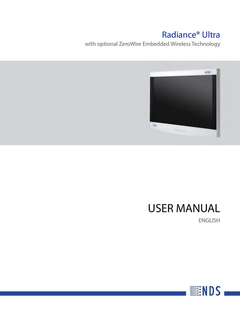
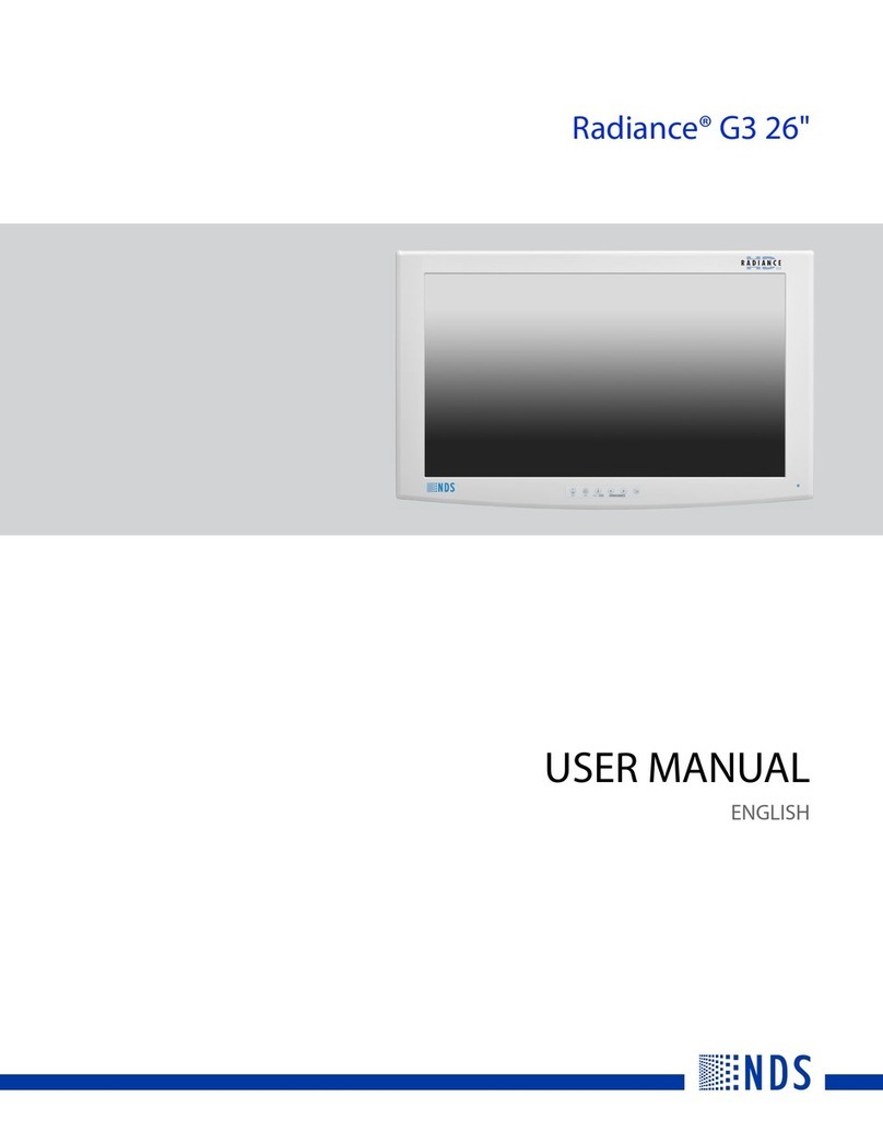
NDS RADIANCE ULTRA 32 4K ZEROWIRE DUO User manual

Radiance® Ultra 32" 4K ZeroWire Duo
60A1071
Instructions for Use
ENGLISH


en © 2022 NDS Surgical Imaging, LLC. All rights reserved.
Information in this document has been carefully checked for accuracy; however, no guarantee is given to the
correctness of the contents. This document is subject to change without notice. NDS provides this informa-
tion as reference only. Reference to products from other vendors does not imply any recommendation or
endorsement.
This document contains proprietary information protected by copyright. No part of this manual may be re-
produced by any mechanical, electronic, or other means, in any form, without prior written permission of
NDS.
All trademarks are the property of their respective owners.


Symbols
Symbols
Follow instructions for
use
Consult instructions for
use
Instructions for use and
translated copies are
published on the NDS
website at:
www.ndssi.com/user-
manuals/
General warning
Warning; Electricity
Authorized Representat-
ive in the European
Community
Medical Device
Authorized for Sale or
use by Physician only
Caution
Manufacturer
Date of manufacture
(YYYY-MM-DD)
Catalogue number
Serial number
Batch code
Atmospheric pressure
limitation
Humidity limitation
Temperature limit
Waste management
Fragile
Keep dry
This way up
Complies to IEC 60601-1
including US and Cana-
dian deviations in their
respective valid version
The Canadian Standards
Association (CSA) certi-
fication mark represents
safety approval by Cana-
dian Standards Associ-
ation for Canada and the
United States.
EurAsian Conformity
(EAC) mark represents
safety approval by Cus-
tom Union countries:
Belarus, Russia, Kazakh-
stan, Armenia, Kyrgyz-
stan.

China Compulsory Certi-
ficate (CCC) mark for In-
formation Technology
Equipment (ITE)
products.
United States Federal
Communications Com-
mission (FCC) symbol in-
dicates EMC compliance
per FCC standards.
UK Authorized Repres-
entative
No hazardous sub-
stances contained in the
device
Contains restricted sub-
stances. The symbol
number refers in years
to the Environmental
Protection Use Period
(EPUP), during which the
product can be safely
used, and following
which should be imme-
diately recycled.
Equipotentiality
Closed (On) Switch.
Open (Off) Switch.
Protective earth; pro-
tective ground
Alternating current
Non-ionizing electro-
magnetic radiation
Symbols

Table of Contents
1 Important User Notes................................................................................................................................. 7
2 Safety Information ..................................................................................................................................... 8
3 Warnings and Cautions.............................................................................................................................. 9
4 General Information.................................................................................................................................11
4.1 Device Requirements....................................................................................................................................................11
4.1.1 System Safety Requirements...................................................................................................................................... 11
4.1.2 Power Supply................................................................................................................................................................... 11
4.1.3 Power Cord .......................................................................................................................................................................11
4.1.4 Grounding......................................................................................................................................................................... 11
4.2 Intended Use.................................................................................................................................................................... 12
5 Display User Interface ..............................................................................................................................13
5.1 Display Keypad................................................................................................................................................................ 13
5.2 OSD Menu Overview.....................................................................................................................................................13
5.3 Keypad Menu Navigation............................................................................................................................................13
5.4 OSD Menu .........................................................................................................................................................................14
5.5 Picture Menu.................................................................................................................................................................... 14
5.6 Color Menu ....................................................................................................................................................................... 16
5.7 Setup Menu ...................................................................................................................................................................... 18
5.8 Input Menu .......................................................................................................................................................................19
6 Connector Panel .......................................................................................................................................21
6.1 Connector Panel .............................................................................................................................................................21
6.2 Data Connectors and Pinouts .................................................................................................................................... 22
6.3 Control Connectors and Pinouts............................................................................................................................... 24
6.4 Electrical Symbols...........................................................................................................................................................25
7 Set up and Installation .............................................................................................................................26
7.1 Positioning and Orientation....................................................................................................................................... 26
7.2 Non Line of Sight Operation.......................................................................................................................................28
7.3 Setting up and linking the displays .........................................................................................................................29
8 Display Specifications ..............................................................................................................................32
9 ZeroWire Specifications ...........................................................................................................................33
10 Supported Resolutions ............................................................................................................................35
11 Installation and Maintenance..................................................................................................................37
11.1 VESA Mounting ...............................................................................................................................................................37
11.2 Cable Cover Installation ............................................................................................................................................... 37
11.3 Cleaning Instructions .................................................................................................................................................... 37
12 Troubleshooting.......................................................................................................................................38
13 Electromagnetic Compatibility Tables ...................................................................................................39
13.1 Guidance and Manufacturer's Declaration - Electromagnetic Emissions ..................................................39
13.2 Guidance and Manufacturer's Declaration - Electromagnetic Interference Immunity......................... 40
13.3 Guidance and Manufacturer's Declaration - Recommended Separation Distances.............................. 41
14 Terms and Conditions ..............................................................................................................................42
14.1 Declarations of Conformity.........................................................................................................................................42
14.2 Legal Statement.............................................................................................................................................................. 43
7 / 45
Important User Notes | 7
1 Important User Notes
Read the instructions for use carefully and become familiar with the operation and function of the device and
the accessories before use during surgical procedures. Non-observance of the instructions listed in this
manual can lead
• to life-threatening injuries of the patient,
• to severe injuries of the surgical team, nursing or service personnel,
• or damages or malfunction of device and/or accessories.
The manufacturer reserves the right to modify the appearance, graphics, and technical data of the product
through continued development of its products.
Please note: Paragraphs marked with the words WARNING, CAUTION, and NOTE carry special meanings. Sec-
tions marked with these words must be given special attention.
WARNING!
The safety and/or health of the patient, user, or a third party are at risk. Comply with this
warning to avoid injury to the patient, user, or third party.
CAUTION!
These paragraphs include information provided to the operator concerning the intended
and proper use of the device or accessories.
NOTE!
These paragraphs contain information to clarify the instructions or provide additional use-
ful information.

8 / 45
8 | Safety Information
2 Safety Information
CAUTION!
Federal law restricts this device to sale by or on the order of a physician.
The manufacturer is not liable for indirect, incidental and consequential damages, including, but not limited
to, loss of profit. Any liability and applicable warranty becomes null and void if:
• the device and/or the accessories/ peripherals are improperly used, transported, stored, prepared, or main-
tained;
• the instructions and rules in the instructions for use are not adhered to;
• unauthorized persons perform repairs, adjustments, or alterations on the device or accessories/peripher-
als;
• unauthorized persons open the device;
• the prescribed inspection and maintenance schedules are not adhered to.
The handing over of technical documents does not constitute authorization to make repairs, adjustments or
alterations to the device or accessories/ peripherals.
WARNING!
Modification of the device is not permitted.
Only an authorized service technician may perform repairs, adjustments, or alterations on the device or ac-
cessories/ peripherals and use the service menu. Any violation will void any applicable warranty. Authorized
service technicians are only trained and certified by the manufacturer.
Waste management
This symbol indicates that the waste of electrical and electronic equipment must not be
disposed as unsorted municipal waste and must be collected separately. For disposal of
the device and its accessories, please consult the manufacturer or an authorized dis-
posal company, in compliance with legal or national regulations.

9 / 45
Warnings and Cautions | 9
3 Warnings and Cautions
This product is T.U.V. approved with respect to electric shock, fire and mechanical hazards only in
accordance with CAN/CSA C22.2 No. 60601-1 and ANSI/AAMI ES60601-1.
This product meets the requirements of EN60601-1 so as to conform to the 2017/745 Medical
Device Regulation of European Union.
WARNING!
Leaving a fixed (constant) image on the monitor for a long period of time can result in im-
age retention. Avoid leaving a fixed image on the monitor, or turn the monitor off when it is
not in use.
WARNING!
Risk of electrical shock
Uninsulated voltage within the unit may have sufficient magnitude to cause electrical
shock. Do not touch any part inside the unit. To reduce the risk of electric shock, DO NOT re-
move the cover or back.
WARNING!
For mission critical applications, we strongly recommend that a replacement ZeroWire 4k
Display Pair and a DVI cable be immediately available. Additionally, we recommend that a
display that is hard wired to the video source be immediately available whenever a surgical
procedure is in progress.
WARNING!
No part of this product may come in contact with a patient. Never touch the product and a
patient at the same time. At any time, a minimum separation of 20 cm must be maintained
from the operating device and the user or patient.
WARNING!
Fire and shock hazard
Do not expose this product to rain or moisture.
WARNING!
Do not use this unit's polarized plug with an extension cord receptacle or other outlets un-
less the prongs can be fully inserted.

10 / 45
10 | Warnings and Cautions
CAUTION!
In case of serious incident
Please report any serious incident that has occurred in relation to the device to the manu-
facturer and the competent authority of the State in which the user and/or patient is estab-
lished.
CAUTION!
This product is a Class I medical device according to the MDR in Europe. No modifications
are allowed.
CAUTION!
This product is a Class II medical device in the United States and Canada. No modifications
are allowed.
CAUTION!
Do not use this product in the presence of flammable anesthetics mixture with air, oxygen
or nitrous oxide.
NOTE!
This equipment/system is intended for use by healthcare professionals only.
NOTE!
There are no user serviceable parts inside. Refer servicing to qualified service personnel.
NOTE!
This product is designed to meet medical safety requirements for a patient vicinity device.
Do not use in MR Environments
Hereby, NDS Surgical Imaging, LLC, declares that this ZeroWire 4K System is in compliance with the essential
requirements and other relevant provisions of Directive 2014/53/EU. The full text of the EU Declaration of Con-
formity is available upon request.
Federal (USA) law restricts this device to sale by or on the order of a physician.
Radio Approval:
This device meets the requirements of EN302 567 and conforms to Radio and Equipment Directive (RED)
2014/53/EU.
FCC Identification: UK2-SII-SK63102, UK2-SII-SK63101 or 2ASUJ-SII-SK63102, 2ASUJ-SII-SK63101
Industry Canada: 6705A-SIISK63102, 6705A-SIISK63101 or 25001-SIISK63102, 25001-SIISK63101
This product complies to the above standards only when used with an NDS supplied medical grade power
supply.

11 / 45
General Information | 11
4 General Information
4.1 Device Requirements
4.1.1 System Safety Requirements
External equipment connected to the signal input/output or other connectors of this product for use in a pa-
tient environment must comply with the requirements of ISO and ANSI/AAMI ES/EN/IEC 60601-1 safety stand-
ards. A person who connects such equipment to this product has by definition formed a system, and is re-
sponsible for compliance of that system to the same ISO and ANSI/AAMI ES/EN/IEC 60601-1 safety standards.
NDS recommends that VIMA installation be conducted by qualified personnel.
4.1.2 Power Supply
This product complies to the listed safety standards only when used with the supplied medical grade power
supply:
Model Radiance® Ultra 32" 4K ZeroWire Duo
Power Supply BridgePower BPM150S24F06
AC Input 100 - 240 V, 50 to 60 Hz
DC Output 24 Vdc, 6.25 A, 150 W
4.1.3 Power Cord
Use the supplied hospital grade power cord with the correct plug for your power source.
• The power cord is the only recognized disconnect device for this product. To power off the product, dis-
connect the power cord from the AC mains.
• The product and other medical equipment should be positioned so that the power cord and connection to
AC mains is readily accessible.
• If an extension cord or power strip is needed for connection of this product to AC mains, confirm that the
power cord plug can be securely connected to the cord or power strip. The low voltage side of the power
supply can only be extended to up to 50 ft.
• This product should be powered from a center tapped circuit when used in the US at voltages over 120V.
4.1.4 Grounding
This product is energized from an external electrical power source for 2017/745 Medical Device Regulation of
European Union Class I equipment. It is the responsibility of the installer to test the product's earth ground to
verify that it complies with the hospital, local and national impedance requirements.
A ground post is located on the back of the product to use for grounding the chassis of the unit. Any such
grounding must be installed in accordance with applicable electrical codes.

12 / 45
12 | General Information
4.2 Intended Use
The Radiance® Ultra 32" 4K ZeroWire Duo is a paired wireless video communication transmitter and re-
ceiver, intended for delivery of video signals from a source such as an endoscopy camera/processor, or other
video source over a radio-frequency link to a ZeroWire Receiver for display of images during endoscopic and
general surgical procedures. The Radiance® Ultra 32" 4K ZeroWire Duo is a non-sterile reuasable device not
intended for use in the sterile field.

13 / 45
Display User Interface | 13
5 Display User Interface
5.1 Display Keypad
The Display Keypad is centered on the lower front surface of the display enclosure, providing controls for ad-
justment of display parameters using the On Screen Display (OSD) Menu system.
5.2 OSD Menu Overview
The OSD Menu provides controls divided into 4 categories: the Picture Menu, the Color Menu, the Setup
Menu, and the Input Menu.
5.3 Keypad Menu Navigation
INPUT Button To directly open the Input Menu, tap the INPUT but-
ton. Input signal options are displayed in the right
column. See Input Menu [}19].
MENU Button To open the OSD Menu, tap the MENU button. The
Picture Menu is initially displayed, with details of the
current input listed above the menu tabs.
SCROLL Button: Vertical Selection
Control
To enter a menu, tap the SCROLL button. The top
parameter row is selected with first tap of the SCROLL
button, and the selection moves downward to the
next row with each successive tap.
To exit a menu, use the SCROLL button to move the
selection to the bottom menu row, and then tap the
SCROLL button just once to highlight the menu tab,
where you can use the or buttons to select an-
other menu tab.
LEFT / RIGHT Buttons: Horizontal Se-
lection Controls
To adjust a parameter, select the parameter row using
the SCROLL button, then tap the or buttons to
select or to change a setting.
COLOR Button
To directly open the Color Menu, tap the COLOR but-
ton. The Color Menu contains Color, Brightness, Con-
trast, and other parameters described in Color Menu
[}16].

14 / 45
14 | Display User Interface
5.4 OSD Menu
Access the OSD Menu by tapping the MENU button. The OSD Menu opens displaying the Picture Menu, with
details of the input listed across the top of the menu above the menu tabs. Operating Hours and Firmware ver-
sion number are listed at the bottom of the menu.
The keypad goes on standby after 5 seconds of inactivity. When the keypad is on standby press the MENU
button to activate the keypad. Press the MENU button again to enter the menu.
To select other menu tabs, tap the or button to highlight a menu tab, then tap the SCROLL button to
enter the menu.
To adjust a parameter, tap the SCROLL button to move the row selection down to it, and then tap the or
button to adjust the parameter or select a setting. Parameter adjustments are applied in real time while chan-
ging values or settings.
The OSD Menu closes automatically 30 seconds after the last action or can be closed by tapping the MENU
button.
NOTE!
Grayed out descriptions indicate parameters not available for the current signal or input
configuration.
5.5 Picture Menu
Horizontal Position
To horizontally center the image, tap the or button.
Vertical Position
To vertically center the image, tap the or button.
Sharpness
To adjust sharpness (edge enhancement) of the displayed image, tap the or button.
= 50: default value displays the image as received.

15 / 45
Display User Interface | 15
> 50: increasing values sharpen the image.
< 50: decreasing values soften the image.
Overscan (Video)
Parameter enabled when the input is 16:9, 480P, 576P, or interlaced. Press the or button to select.
0: The image is displayed at a size that fills the screen without losing any video information. Image could be
displayed as letterboxed, with black bars top and bottom or left and right.
1, 2, 3, 4, 5 or 6: Incrementally enlarges and crops the centered image. As the image becomes larger, video in-
formation is lost on all sides.
NOTE!
The Link Menu may not be accessible when using Overscan. Displays should be linked ber-
fore using this function.
Scaling
To select a scaling option, tap the or button.
Fill: Expands the video image to fill the entire screen. The aspect ratio may not be accurately displayed.
Aspect: Expands the video image until its largest dimension fills the screen while retaining the aspect ratio.
The image may be displayed as letterboxed, with black bars top and bottom or left and right.
1:1: Displays the video data in its native size and aspect ratio. Images with resolution less than the 4K/UHD
native 3840 x 2160 resolution are displayed with a black background surrounding the image.
NOTE!
Scaling options are limited to Aspect when overscan settings are > 0.
Rotation
The rotation option rotates the orientation of the screen per the option selected.
• To select the screen orientation, tap the or button.
•Off: No screen orientation change.
•180: Rotates the screen 180°.
•V-Flip: Rotates the screen vertically 180°.
•H-Flip: Rotates the screen horizontally 180°.
NOTE!
Image Rotation is not supported for interlaced signals.
NOTE!
The Link Menu may not be accessible when using rotated images. Displays should be linked
berfore using this function.
Rotation OSD
The rotation ODS option displays the screen orientation indicator on the screen at the selected interval.
Select the screen rotation indication option: Off, On, 10 seconds, Blink.

16 / 45
16 | Display User Interface
5.6 Color Menu
Open the Color Menu directly by tapping the COLOR tab.
Gamma
To select a gamma setting, tap the or button.
1.8, 2.0, 2.2, 2.4 or 2.6: Preset gamma values
Video: Linear gamma Look Up Table (LUT)
PACS: DICOM gamma LUT
This product is capable of displaying Radiology (PACS) images for reference purposes only.
Color Temperature
To select a preset color temperature, tap the or button.
5500, 6500, 8000, 9300: Preset color temperatures.
User: With a preset color temperature selected, if any other color parameter is subsequently adjusted from the
default setting, the resulting values are copied to the color temperature User presets and User is selected.
Red / Green / Blue
To adjust balance of the selected color in the image, tap the or button.
Saturation (available only for YUV inputs)
To adjust saturation (color intensity) of the image, tap the or button.
Hue (available only for YUV inputs)
To adjust hue (color) of the image, tap the or button.
Brightness
To darken or lighten the image, tap the or button.
Contrast
To adjust contrast of the image, tap tap the or button.

17 / 45
Display User Interface | 17
Video Level
To select a video level setting, tap the or button.
Normal: The incoming signal is displayed without modification.
Expanded: Expands a Limited Range 16–235 signal (220 shades from black to white) to a Full Range 0–255
signal (256 shades from black to white).
NOTE!
Expand Setting
Application of the Expanded setting to a Full Range signal will clip the image, with loss of
detail in dark and light areas.
Color Correction
To select a color correction setting, tap the or button.
NDS: Bypasses the color correction feature.
BT.709: Factory calibrated to meet the BT.709 standard.
BT.2020: Factory calibrated to emulate the BT.2020 standard.
Auto Color Correction
When Auto Color Correction is ON, color correction will be selected based on the input signal:
Auto Color Correction Settings by Input and resolution type:
HDMI-1 HDMI-2 Display
Port 1
Display
Port 2
DVI 12G-SDI ZW Re-
ceiver
Graphic NDS NDS NDS NDS NDS NDS NDS
Standard
Definition BT.709 BT.709 BT.709 BT.709 NDS NDS BT.709
High Defini-
tion BT.709 BT.709 BT.709 BT.709 NDS NDS BT.709
Ultra High
Definition BT.2020 BT.2020 BT.2020 BT.2020 NDS NDS BT.2020
NOTE!
Refer to chapter Supported Resolutions for resolution types associated with each input sig-
nal.

18 / 45
18 | Display User Interface
5.7 Setup Menu
Menu Position
To select from 4 preset screen locations for display of the OSD menu, tap the or button.
Language
To select one of eight languages: English, Deutsch, Français, Italiano, Svenska, Español, Nederlands, or
Pycckий, tap the or button.
DPMS Enable
To enable or disable Display Power Management System (DPMS), tap the or button.
Off: Default setting.
On: If there is no input signal, a DPMS message displays for 10 - 15 seconds be-
fore the display goes into Power Saving mode. The display turns on when the
input signal is restored.
Menu Lock
To enable Menu Lock. Tap the button.
Off: Default setting.
On: Disables access to all OSD menus except the Input Menu. The OSD Menu
closes, and a MENU LOCKED message displays briefly. To unlock OSD access,
simultaneously press the MENU and SCROLL buttons until the MENU UN-
LOCKED message displays.
Backlight
To adjust the backlight level of the display, tap the or button.
Backlight Stabilization
To enable or disable backlight stabilization, tap the or button.
Table of contents
Other NDS Monitor manuals

NDS
NDS DTB01 User manual

NDS
NDS DOMETIC SL12-100 User manual

NDS
NDS DTB01 User manual

NDS
NDS DTB01 User manual

NDS
NDS Radiance Ultra 4K User manual

NDS
NDS GX2MP User manual

NDS
NDS EndoVue Plus 24 User manual

NDS
NDS Radiance Ultra SERIES User manual

NDS
NDS Dometic IM12-150 Owner's manual

NDS
NDS EndoVue SC-SX19 User manual