NED GiGE VISION RCDL4K8GE User manual

User’s Manual
Line Scan Camera
Type:RCDL4K8GE
NIPPON ELECTRO-SENSORY DEVICES CORPORATION
GigE Vision is a registered trademark ofAIA

NED
RCDL4K8GE UME-0111-01
2
For Customers in the U.S.A.
This equipment has been tested and found to comply with the limits for a Class A
digital device, in accordance with Part 15 of the FCC Rules. These limits are designed
to provide reasonable protection against harmful interference when the equipment is
operated in a commercial environment. This equipment generates, uses, and can
radiate radio frequency energy and, if not installed and used in accordance with the
instruction manual, may cause harmful interference to radio communications.
Operation of this equipment in a residential area is likely to cause harmful interference,
in which case the user will be required to correct the interference at his or her own
expense.
For Customers in the EU
This equipment has been tested and found to comply with the essential requirements
of the EMC Directive 2004/108/EC, based on the following specifications applied:
EU Harmonised Standards
EN55032:2015 Class A
EN55032:2012 Class A
EN55011:2009+A1:2010 Class A
EN61000-6-2:2005
Directive on Waste Electrical and Electronic Equipment (WEEE)
Please return all End of Life NED products to the distributor from whom the product
was purchased for adequate recycling and / or disposal. All costs of returning the
Product to NED are borne by the shipper.
NED
UME-0111-01 RCDL4K8GE
3
Introduction
Thank you for purchasing NED’s Line Scan Camera. We look forward to your
continued custom in the future.
For safety use
◆For your protection, please read these safety instructions completely before
operating the product and keep this manual for future reference.
◆The following symbols appear next to important information regarding safe product
handling.
Warning
If the product is not handled properly, this may result in
serious injury or possible death.
Caution
If the product is not handled properly, this may result in
physical injury or cause property damage.
Safety precaution
Warning
◆Never disassemble or modify this product, unless otherwise specified to do so in
this manual.
◆When hands are wet, avoid handling this product and do not touch any of the
connection cable pins or other metallic components.
◆Do not operate this product in an environment that is exposed to rain or other
severe external elements, hazardous gases or chemicals.
◆If the product is not to be used for an extended period of time, as a safety
precaution, always unplug the connection cable from the camera unit.
◆If the product installation or inspection must be executed in an overhead location,
please take the necessary measures to prevent the camera unit and its
components from accidentally falling to the ground.
◆If smoke, an abnormal odor or strange noise is emitted from the camera unit, first
turn OFF power, then unplug the cable from the camera unit.
◆This product is not intended for use in a system configuration built for critical
applications.

NED
RCDL4K8GE UME-0111-01
4
Instructions before use
◆Only operate this product within the recommended environmental temperature
range.
◆Use only the specified power source and voltage rating.
◆Do not drop this product.Avoid exposure to strong impact and vibrations.
◆Install the camera unit in a well-ventilated environment, in order to prevent the
camera from overheating.
◆If the camera must be installed in an environment containing dust or other particles,
take required measures to protect the camera unit from dust adhesion.
◆Do not unplug the cable while power is being supplied to the camera unit. To
prevent product damage, always shut down the power supply before unplugging
the power cable.
◆When the surface of the camera window becomes dirty due to dust or grime, black
smudges appear in the displayed image. Use an air blower to remove the dust
particles. Dip a cotton swab into ethanol alcohol and clean the camera window. Be
careful not to scratch the glass.
◆Use of non-infrared lighting such as a fluorescent lamp is recommended. If halogen
lighting is employed, always install an infrared filter into your system configuration.
◆Note that exposure to long wavelength light outside of the sensors visible optical
range can affect the image.
◆Sensitivity may fluctuate depending on the spectral response level of the light
source. In cases like this, changing the light source to one with a different spectral
response level may reduce this problem. Moreover, this irregular sensitivity can be
completely lost by using 4.8 pixel correction function. Please refer to 4.8 pixel
correction function for details.
◆Note that when the sensor is exposed to excessive quantities of light, blooming
may occur, because this product does not have a special Anti-Blooming function.
◆Suitable measures should be taken to protect the colour filter on sensor from bright
light when it is not in use.
If the sensor is continually exposed to excessive amount of light over time, the
colour filter may become faded.
◆For stabilized image capturing, turn on the power supply and execute aging for ten
to twenty minutes before actually using the camera unit.
◆Do not share the power supply with motor units or other devices that generate
noise interference.
◆Do not disconnect the camera while rewriting the embedded memory.
◆When you change the exposure mode that is set at the NED factory, input
control signal (CC1) from the capture board.
◆SG (Signal Ground) and FG (Frame Ground) are connected inside the camera.
Please install your system such that a loop is not created by the GND potential
difference.

NED
UME-0111-01 RCDL4K8GE
5
Product Warranty
Warranty Period
◆The product warranty period, as a general rule, is two years from purchase;
however for detailed conditions please contact the sales representative for your
region/country.
◆However, in some cases due to the usage environment, usage conditions and/or
frequency of use, this warranty period may not be applicable.
Warranty Scope
◆Product repair will be performed on a Return To Manufacturer basis. On-site
maintenance will incur additional charges.
◆If defects in material or workmanship occur during the warranty period, the faulty
part will be replaced or repaired by us free of charge. Return shipping charges
must be paid by the sender. However, the following cases fall outside of the scope
of this warranty:
◆The expired date of the warranty period on the product repaired or replaced during
the warranty period of the original product is the same as the expired date of the
warranty period on the original product.
Exclusions from Warranty Coverage
◆We will under no circumstances assume responsibility for the following cases:
damage caused by fire, earthquake, other acts of a third party, other accidents,
negligent or intentional misuse by the user, or other usage under extraordinary
circumstances.
◆Damages (e.g. loss of business profits, business interruption, etc.) resulting from
use or non-use.
◆Damages caused by use other than as described in this document.
◆Damages resulting from malfunction due to a connected device.
◆Damages resulting from repairs or modifications performed by the customer.
Fault Diagnosis
◆As a general rule, in the first instance fault diagnosis should take the form of a
telephone call or an email to enable us to assess the circumstances of the
malfunction.
◆However, depending on the customer’s requests, we, or our agent, may require an
additional fee for this service.

NED
RCDL4K8GE UME-0111-01
6
Exclusion of Liability for Compensation for Missed Opportunities
◆Regardless of whether within the warranty period or not, our warranty does not
cover compensation for missed opportunities for our customers, or our customers’
customers, caused by a fault of our products, nor for damage to products other
than our own, or related business.
Note about Product Usage
◆This product has been designed and manufactured as a general-purpose product
for general industry. In applications expected to be life-critical or safety-critical, the
installer or user is requested to install double or triple failsafe systems.
Repair Service Outline
◆The cost of dispatching engineers etc. for repair service is not included in the price
of purchased and supplied goods. On request, arrangements can be made
separately.
Scope of Repair Service
◆The above assumes business dealings and usage to take place in the customer’s
region / country. In cases of business dealings and/or usage outside the
customer’s region/country, separate consultation is required.

NED
UME-0111-01 RCDL4K8GE
7
Table of Contents
1 Product Outline ....................................................................11
1.1 Features..................................................................................................................................11
1.2 Applications...........................................................................................................................11
1.3 Image Sensor.........................................................................................................................13
1.4 RGB Synthesis method with Bayer at pixel.......................................................................13
1.5 Performance Specifications.................................................................................................14
2 Camera Setting and Optical Interface ................................16
2.1 Setting Camera......................................................................................................................16
2.2 Fixing Camera........................................................................................................................16
2.3 Optical Interface....................................................................................................................18
2.4 Calibration with User White Pixel Correction Function....................................................19
3 Hardware...............................................................................21
3.1 Camera Connection ..............................................................................................................21
3.2 Input / Output Connectors and Indicator............................................................................23
3.3 Power Supply Connection....................................................................................................24
3.4 External Trigger Connector(HR10G-10R-12PB)............................................................25
3.4.1 RS-422 Input....................................................................................................................26
3.4.2 LVDS Input.......................................................................................................................26
3.4.3 TTL Input..........................................................................................................................27
3.4.4 RS-422 Output.................................................................................................................27
3.4.5 LVDS Output....................................................................................................................28
3.4.6 TTL Output.......................................................................................................................28
3.4.7 Relation of External Trigger Input and Output............................................................29
3.5 RJ-45 Connector....................................................................................................................30
3.6 LED indicating camera status..............................................................................................30
4 Camera Control ....................................................................31
4.1 Flow of Camera Control........................................................................................................31
4.1.1 GenICam overview .........................................................................................................31
4.1.2 List of Camera Control Registers.................................................................................31
4.2 Details on register system ...................................................................................................38
4.2.1 Category ..........................................................................................................................38
4.2.2 Device Control ................................................................................................................39

NED
RCDL4K8GE UME-0111-01
8
4.2.2.1 Displaying Temperature of Camera........................................................................39
4.2.3 Image Format Control....................................................................................................40
4.2.3.1 OffsetX and Width Settings.....................................................................................40
4.2.3.2 Height Setting ..........................................................................................................41
4.2.3.3 Setting Pixel Horizontal Binning Mode..................................................................42
4.2.3.4 Setting Horizontal Pixel Binning............................................................................42
4.2.3.5 Setting Pixel Vertical Binning Mode.......................................................................42
4.2.3.6 Setting Vertical Pixel Binning.................................................................................43
4.2.3.7 Scan Direction...........................................................................................................43
4.2.3.8 Pixel Format Setting ................................................................................................43
4.2.3.9 Test Pattern ..............................................................................................................44
4.2.4 Acquisition Control ........................................................................................................47
4.2.4.1 Setting Line Rate......................................................................................................47
4.2.4.2 Setting Trigger Selector ...........................................................................................48
4.2.4.3 Setting Permission for using External Trigger ......................................................48
4.2.4.4 Setting Trigger signal ..............................................................................................49
4.2.4.5 Setting Exposure Mode ............................................................................................49
4.2.4.6 Setting Exposure Time.............................................................................................50
4.2.5 Analog Control................................................................................................................51
4.2.5.1 Setting Analog gain ..................................................................................................51
4.2.5.2 Gain type selection ...................................................................................................51
4.2.5.3 Setting Digital gain..................................................................................................52
4.2.5.4 Offset type selection .................................................................................................52
4.2.5.5 Setting Digital Offset ...............................................................................................53
4.2.5.6 Setting Balance White Auto ....................................................................................53
4.2.5.7 Setting Gamma correction.......................................................................................53
4.2.6 Color Transformation Control.......................................................................................54
4.2.6.1 Color Transformation settings.................................................................................54
4.2.6.2 Select Color Transformation item ...........................................................................54
4.2.6.3 Setting Color Transformation Value .......................................................................56
4.2.7 Digital IO Control............................................................................................................56
4.2.7.1 Setting I/O signal......................................................................................................56
4.2.7.2 Setting Line Mode ....................................................................................................56
4.2.7.3 Setting Input Signal Polarity Reversal ..................................................................57
4.2.7.4 Setting Line Source ..................................................................................................57
4.2.7.5 Setting I/O Signal Format .......................................................................................58
4.2.7.6 Setting External Line Trigger Chattering Prevention ..........................................59
4.2.8 Encoder Control..............................................................................................................59

NED
UME-0111-01 RCDL4K8GE
9
4.2.8.1 Setting Encoder Control ..........................................................................................59
4.2.8.2 Setting Input Signal for Encoder Source A ............................................................60
4.2.8.3 Setting Input Signal for Encoder Source B ............................................................60
4.2.8.4 Setting Encoder Mode..............................................................................................60
4.2.8.5 Setting Encoder Divider...........................................................................................61
4.2.8.6 Setting Encoder Output Mode.................................................................................62
4.2.8.7 Setting Encoder Status ............................................................................................62
4.2.8.8 Setting Time of Encoder Timeout............................................................................62
4.2.8.9 Setting Encoder Reset Signal ..................................................................................63
4.2.8.10 Setting Encoder Reset Activation..........................................................................63
4.2.9 User Set Control .............................................................................................................64
4.2.9.1 Setting Memory Selection........................................................................................64
4.2.9.2 Setting Memory Loading .........................................................................................64
4.2.9.3 Setting Memory Saving............................................................................................65
4.2.9.4 Resetting Factory camera setting ...........................................................................65
4.2.10 Transport Layer Control...............................................................................................66
4.2.10.1 Setting Persistent IP..............................................................................................66
4.2.10.2 Packet Size..............................................................................................................67
4.2.10.3 Packet Delay ...........................................................................................................68
4.2.11 NED additional features...............................................................................................69
4.2.11.1 Setting Pixel Correction.........................................................................................69
4.2.11.2 Setting Pixel Correction Target Value ..................................................................69
4.2.11.3 Saving White Pixel Correction Data .....................................................................70
4.2.11.4 Saving Black Pixel Correction Data......................................................................70
4.2.11.5 Setting conditions of White pixel correction and Black correction .....................70
4.3 Setting Procedure of External Trigger Settings (for Examples) ......................................71
4.3.1 One-phase Trigger setting (for Example).....................................................................71
4.3.2 Two-phase Trigger setting (for Example).....................................................................72
4.3.3 Software Trigger setting (for Example)........................................................................73
4.4 Calculating the Maximum Value of Packet Delay ..............................................................75
4.5 Exposure Mode and Timing.................................................................................................75
4.5.1 Free run Exposure Mode ...............................................................................................76
4.5.2 External Trigger (Timed) Exposure Mode....................................................................77
4.5.3 External Trigger (TriggerWidth) Exposure Mode........................................................78
4.6 Setting Offset.........................................................................................................................79
4.7 Setting Gain ...........................................................................................................................80
4.8 Pixel Correction.....................................................................................................................82
4.9 Gamma Correction Setting...................................................................................................83

NED
RCDL4K8GE UME-0111-01
10
5 Basic Camera Setting Checks ............................................84
5.1 Before Power On...................................................................................................................84
5.2 After Power On......................................................................................................................84
6 Sensor Handling Instructions.............................................85
6.1 Electrostatic Discharge and the Sensor.............................................................................85
6.2 Protecting Against Dust, Oil and Scratches.......................................................................85
6.3 Cleaning the Sensor Window...............................................................................................85
7 Troubleshooting...................................................................86
7.1 No Image ................................................................................................................................86
7.2 Noise on Image......................................................................................................................88
7.3 Camera becomes hot............................................................................................................89
8 Others....................................................................................90
8.1 Notice......................................................................................................................................90
8.2 Contact for support...............................................................................................................90
8.3 Product Support....................................................................................................................90

NED
UME-0111-01 RCDL4K8GE
11
1 Product Outline
1.1 Features
⚫Color line scan camera with 7μm 4096 x 2 pixels sensor of Bayer color
arrangement
⚫Easy control of gain / offset / video output with external software
⚫GigE Vision® external interface for easy connection between camera
and PC
⚫Data transmission up to 100m using a CAT-5e cable or above
⚫Single power source DC12~15V for operation
⚫Pixel non-linearity / shading correcting function
1.2 Applications
⚫Inspection of transparent panels and PCBs
⚫Inspection of high speed moving objects
⚫Flat panel display inspection
⚫Inspection of glass and sheet-like objects
⚫Printed circuit board inspection
⚫This camera utilizes an Intelligent Transportation System
⚫Outdoor surveillance

NED
RCDL4K8GE UME-0111-01
12
An example of visual inspection of metallic parts is shown below.
Figure 1-2-1 Visual Inspection of Metallic Cylinder
Object of inspection (example)
Metallic parts with cylindrical/conical shapes (surface and roller end faces)
・Automobile component ・Architectural reinforcement parts
・Various pin parts
Typical detection item
・Chip ・Dent ・Scratch ・Chipped end faces ・External dimensions
Device specification
1. Camera: 4096 pixel Line scan camera
2. Controller: Dedicated software for PC system
Line scan Camera
Object of inspection
■Example using one camera.
(Inspection of surface)
■Example using three cameras.
(Inspection of surface and end faces)
NED
UME-0111-01 RCDL4K8GE
13
1.3 Image Sensor
This camera has a Bayer array dual of 4096 pixels with a pixel size of 7 μm x 7 μm
Aline color CMOS sensor is used to obtain high sensitivity and high quality images.
・The sensor array is as follows.
R
G
R
G
G
B
G
B
7μm
7μm
7μm
R
G
G
B
4096 4095 6 5 2 1
R
G
G
B
4 3
7μm
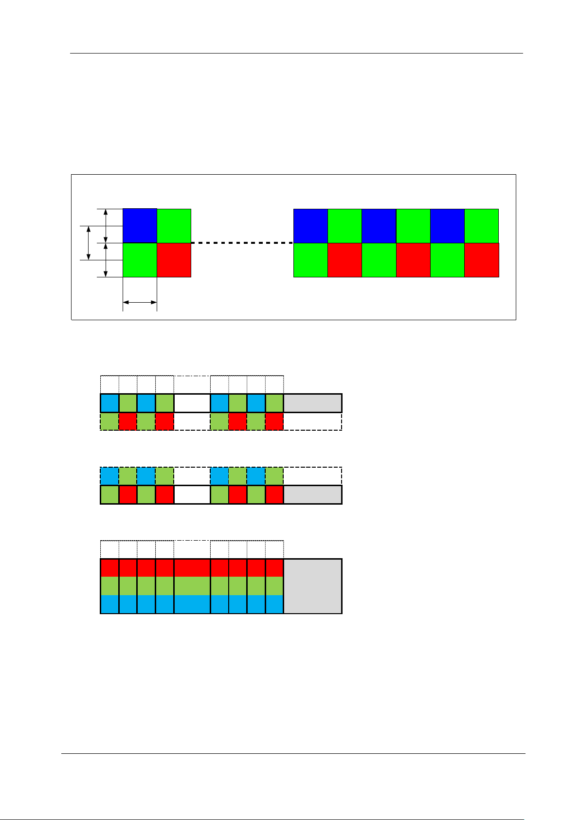
1.4 RGB Synthesis method with Bayer at pixel
4096 4095 4094 4093 4 3 2 1
B1 G1 B1 G1 B1 G1 B1 G1 Y coordinate #1
G0 R0 G0 R0 G0 R0 G0 R0 Y coordinate #0
The object moves for one column of pixels and is scanned.
The object moves for next one column of pixels and is scanned.
B2 G2 B2 G2 B2 G2 B2 G2 Y coordinate #2
G1 R1 G1 R1 G1 R1 G1 R1 Y coordinate #1
The scanned values of G1 and B1 of the upper column of pixels at Scan #1
and the scanned values of G1 and R1 of the lower column of pixels at Scan #2 are held in memory.
4096 4095 4094 4093 4 3 2 1
R1 R1 R1 R1
G1 G1 G1 G1 G1 G1 G1 G1
B1 B1 B1 B1
The values of R at even numbering pixels and B at odd numbering pixels are determined by interpolation.
RGB color values at each pixel can be synthesized using the above data.
RGB color
(Y coordinate #1)
Scan #1
Scan #2
⇓

NED
RCDL4K8GE UME-0111-01
14
1.5 Performance Specifications
The Performance Specifications are shown below. The data is shown when the
camera is operating at the maximum scan rate, unless otherwise specified.
Table 1-5-1 Performance Specifications
Items
Specifications
Number of Pixels
4096
Pixel Size H x V (μm)
7x7
Sensor Length (mm)
28.672
Data Rate (MHz)
125
Scan Rate [kHz]/ (μs)
RGB 8 Packed
8.4 / (119.0)
Responsivity (V/ [lx・s]) (typically)
[Minimum Gain, Pixel Correction Initial
Value]
40
Analog 5V Conversion Sensitivity/
Gain Adjustable Range
Analog Amplifier +Digital
Analog Amplifier:x 1 ~x 10
Digital(ALL) :x 1 ~x 2
Digital(R,G,B) :x 1 ~x 3
Digital Offset Adjustable Range (DN)
ALL:-40~40
R,G,B:-20~20
Video output format
GigE
Control Input
Line In1~3:
Exposure trigger, Frame trigger or Encoder signal
Connectors
Data/Controller
RJ45
Power Supply
Hirose: HR10G (6Pin)
External Trigger
Hirose: HR10G (12Pin)
Lens Mount
F Mount
Operating Temperature (˚C)
No Condensation
0 ~50
Power Supply Voltage (V)
DC12 ~15[±5%]
Consumption Current (mA) *typically
610
Size W x H x D (mm)
60x91.3x100 (F Mount)
Mass (g) (Camera only)
475 (F Mount)
Additional Functions
1.Auto White Balance
2.Shading Correction
3.Gain/Offset /Video Output Control
4.Programmable Exposure Control
5.Software Torigger
6.Test Pattern Output
7.Two-phase Trigger
NED
UME-0111-01 RCDL4K8GE
15
8.2×2 Binning Mode
9.RGB Color Matrix Transforming
10.Gamma Transforming
Remarks: 1)DN : Digital Number (8bit : 0 -255 / 10bit : 0 -1023)
2)Measurements were made at room temperature
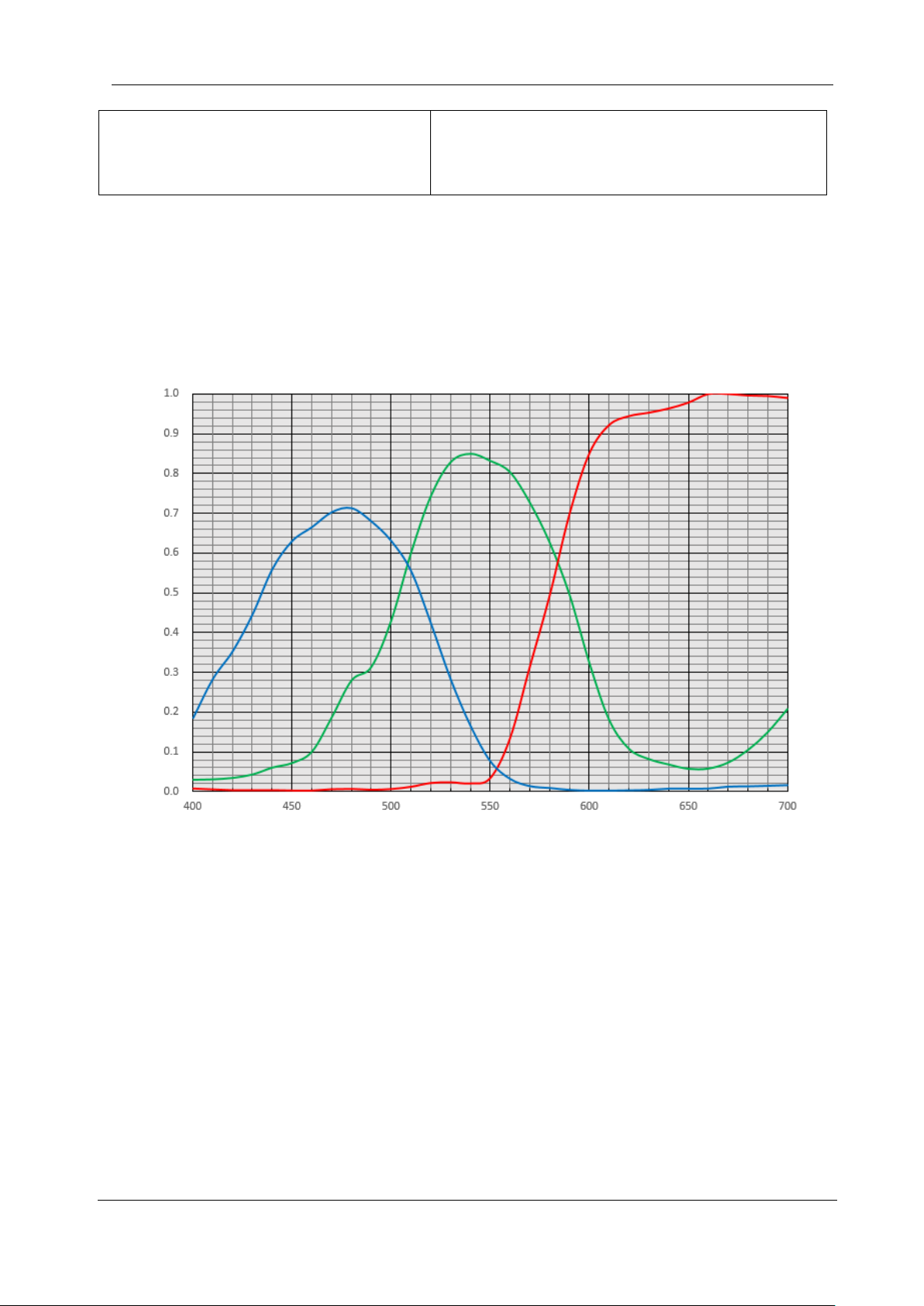
The spectral Responsivity is shown below.
Figure 1-5-1 Spectral Responsivity
Wave Length[nm]
Quantum efficiency(%)
Quantum efficiency

NED
RCDL4K8GE UME-0111-01
16
2 Camera Setting and Optical Interface
2.1 Setting Camera
Use the M4 screw holes or the screw hole for a tripod to set the camera.
2.2 Fixing Camera
Use the M4 screw holes (4 places at the front, 8 places at the side) to fix the
camera. Or use the 1/4"-20UNC screw hole (the screw hole for a tripod, 1 place at
the side) to fix the camera.
If using the front panel M4 mounting holes, the screw length for fixing the camera
should be less than 6mm.
No X-, Y-axis orientation and tilt adjustment mechanism is available. Please provide an
adjustment mechanism yourself as necessary.

NED
UME-0111-01 RCDL4K8GE
17
The dimensions for camera are shown below.
Figure 2-2-1 Dimensions (F Mount)

NED
RCDL4K8GE UME-0111-01
18
2.3 Optical Interface
The amount and wavelengths of light required to capture useful images depend on
the intended use. Factors include the property, speed, the object’s spectral
characteristics, exposure time, the light source characteristics, the specifications of
the acquisition system and so on.
The exposure amount (exposure time x light amount) is the most important factor
in getting desirable images. Please determine the exposure amount after studying
what is most important to your system.
Keep these guidelines in mind when setting up your light source:
⚫LED light sources are relatively inexpensive, provide a uniform field and longer
life span compared to other light sources. However, they also require a camera
with excellent sensitivity.
⚫Halogen light sources generally provide very little blue relative to infrared light
(IR).
⚫Fiber-optic light distribution systems generally transmit very little blue light
relative to IR.
⚫Metal halide light sources are very bright but have a shorter life span compared
to other light sources.
Generally speaking, the brighter light sources, shorter life span.
CMOS image sensors are sensitive to infrared (IR). We recommend using daylight
color fluorescent lamps that have low IR emissions. If you use a halogen light source,
to prevent infrared from distorting the images use an IR cutoff filter that does not
transmit IR wavelengths.

NED
UME-0111-01 RCDL4K8GE
19
2.4 Calibration with User White Pixel Correction Function
This camera is set to the optimal pixel correction with a daylight fluorescent lamp
(NEC FL20SD) before shipping.
Light sources and lens shading can cause non-uniformity.
Calibrate the camera with a user white pixel correction function to cope with lens
shading and non-uniform illumination by following below steps.
1) Set the lens and light source which you want to use.
2) Set NED_FFCMode to "Factory White".
3) Adjust the exposure time and gain to set the signal level to about 200 DN.
4) Execute NED_PRNUCalibration.
5) Change NED_FFCMode to "User White".
This calibration can improve the white balance and the waveform flatness of
the camera signal.
See below for more details.
4.1.2 List of Camera Control Registers
4.2.11 NED additional features
4.8 Pixel Correction
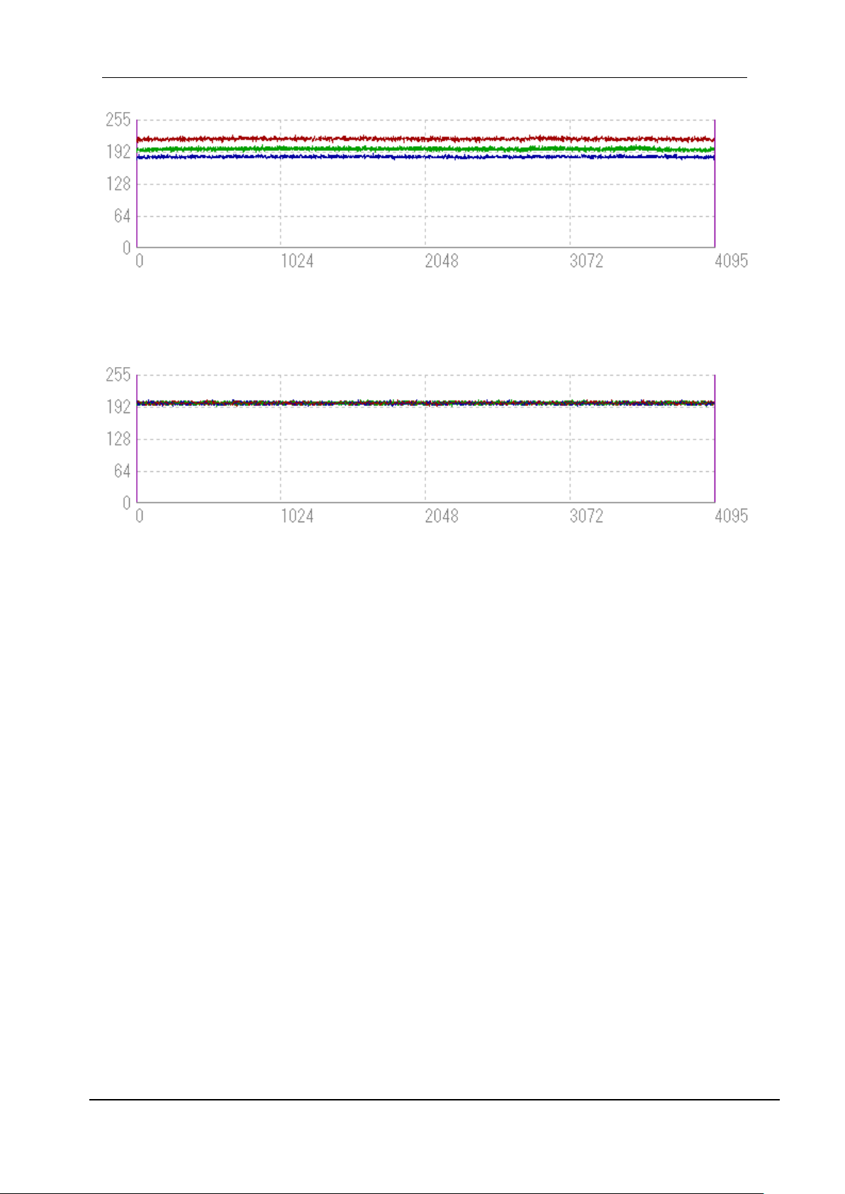
The waveforms at the calibration processing are shown as an example of
this explanation when you use 3-wavelength fluorescent lamp with this camera.
(1) Waveforms using daylight fluorescent lamp
The waveform using daylight fluorescent lamp NEC FL20SD with
this camera is flat after adjusting white balance at Factory.
(2) Waveforms using 3-wavelength fluorescent lamp
The waveforms using 3-wavelength fluorescent lamp with this camera
at Factory white mode are shown below.
The white balance is broken.
NED
RCDL4K8GE UME-0111-01
20
(3) Waveforms using 3-wavelength fluorescent lamp
The waveforms using 3-wavelength fluorescent lamp with this camera
are flat after adjusting white balance with User white mode.
Table of contents
Other NED Digital Camera manuals


NED
NED XCM8085DLMT8 User manual

NED
NED XCM2085DLCT3 User manual

NED
NED SUCL2025T3 User manual

NED
NED RMSL8K39CL User manual

NED
NED XCM2080SAT4 User manual

NED
NED XCM6040SAT2 User manual

NED
NED XCM16K80SAT8 User manual

NED
NED CoaXpress XCM80160CXP User manual

NED
NED XCM6040SAT2 User manual

NED
NED RMSL6K17GE User manual


