Nedap SmartFlow User manual

Instruction Manual
Nedap SmartFlow
Installation manual
Version 00.001 / September 2020 / EN
Original instructions
Dairy Farming

Copyright
Copyright © Nedap N.V. All rights reserved. The information in this document is subject to change without
notice, it is not to be reproduced in any way, in whole or in part, without the written consent of Nedap N.V. All
trademarks referenced belong to their respective owners.
Disclaimer
Nedap N.V. has made every effort to ensure the accuracy of the information contained in this document.
However, Nedap N.V. makes no representations or warranties whatsoever whether express or implied as
to the accuracy, correctness, completeness or fit-for-purpose or suitability for the purpose of this product.
You use the products at your own risk. Nedap N.V. excludes any liability to the maximum extent permitted by
applicable law for the damages caused by errors or failures made during the installation or improper use of
this product or by not applying the instructions stated in this document. Nedap N.V. reserves the right to make
improvements or amendments to this document and/or the products described therein at any time without any
notification. The latest version of this document can be found on the Nedap Livestock Management business
portal (www.nedap.com/livestockmanagement-portal). Please download the latest version of this document (by
yourself or reseller) and keep a copy for your own records. This document can be published in various languages
but only the English language version will prevail. Nedap N.V. assumes no responsibility for any errors caused for
the translations into another language.
Warranty and spare parts
Please consult the Nedap products dealer from whom you purchased this product, in regards to the applicable
warranty conditions. This product cannot be used for any other purpose as described in this document. If
the product is not installed according to this document; the warranty provided is not applicable. At the sole
discretion of Nedap N.V., Nedap N.V. may decide to change the conditions of the warranty policy. You agree
that Nedap N.V. is able to compensate you the pro-rata value of the warranty involved rather than replacing
or repairing the product depending on the technical or economical value of the product. Prior to applying the
warranty, please verify if you comply with the warranty conditions of the warranty policy, whether you can
successfully apply for the replacement or repair of a defective part. Parts can only be replaced with original
Nedap parts, otherwise the warranty policy will not be applicable on the product. If the warranty is applicable,
please contact the dealer or send the defective parts to the dealer.
Additional information
For any information or questions regarding the product, please contact your own dealer.

Nedap SmartFlow / Installation manual
Version 00.001 / September 2020 / EN
1
Dairy Farming
Nedap SmartFlow

Nedap SmartFlow / Installation manual
Version 00.001 / September 2020 / EN
2
Dairy Farming
Content
1 Safety .................................................................................................. 3
2 SmartFlow overview ............................................................................. 5
2.1 SmartFlow introduction .................................................................................................. 5
3 Installation ........................................................................................... 9
3.1 Requirements for installation ........................................................................................ 9
3.1.1 Electrical requirements .................................................................................................... 9
3.1.2 Network requirements ................................................................................................... 10
3.1.3 Electromagnetic requirements ...................................................................................... 10
3.2 Installation overview .................................................................................................... 11
3.3 Mount the components ................................................................................................ 11
3.3.1 Mount the SmartFlow .................................................................................................... 11
3.3.2 Prepare the Float ........................................................................................................... 18
4 Configuration ...................................................................................... 23
4.1 Configure the Velos software ...................................................................................... 23
4.2 Calibrate and validate the SmartFlow ......................................................................... 23
4.2.1 Zero-point test ............................................................................................................... 24
4.2.2 Milk test .......................................................................................................................... 25
4.2.3 Statistic test ................................................................................................................... 25
5 Commissioning ................................................................................... 28
5.1 Cleaning ........................................................................................................................ 28
5.1.1 Cleaning requirements ................................................................................................... 28
5.1.2 Clean the SmartFlow ..................................................................................................... 29
5.2 Inform the end user ..................................................................................................... 29
6 Maintenance ....................................................................................... 30
6.1 Maintenance scheme ................................................................................................... 30
7 Troubleshooting .................................................................................. 31
8 Handling instructions .......................................................................... 32
9 Glossary ............................................................................................. 33
10 Technical specifications ...................................................................... 34
11 Compliance ........................................................................................ 35

Nedap SmartFlow / Installation manual
Version 00.001 / September 2020 / EN
3
Dairy Farming
1 Safety
Read this manual before using this product. Failure to follow the instructions and safety precautions in this
manual may result in serious injury or death. Keep this manual in a safe location for future reference.
Symbols used in the manual
Danger
Indicates a hazardous situation that, if not avoided, will result in death or serious
injury.
Warning
Indicates a hazardous situation that, if not avoided, could result in death or serious
injury.
Caution
Indicates a hazardous situation that, if not avoided, could result in minor or moderate
injury.
Indicates important information but not hazard related.
Suggestions and advice to perform certain tasks more easily.
General safety instructions
Warning
Always turn off the mains power supply when working on the electrical installation.
Warning
Always wear proper protection when installing and maintaining the Nedap SmartFlow.
Caution
Installation and service should only be done by locally qualified personnel.
Caution
Install the system according to the local rules and regulations.
Caution
We advice to install and maintain the Nedap SmartFlow with at least 2 persons.
Working environment
Caution
The installation area must be free from any obstacles, including animals.

Nedap SmartFlow / Installation manual
Version 00.001 / September 2020 / EN
4
Dairy Farming
Caution
Make sure all components are installed out of reach of animals.
Caution
Make sure all cables are properly concealed, and form no danger for stumbling.
Animal welfare and safety
The automated actions of the Nedap Livestock Management systems do never discharge the installer and the
user of the system from his/her responsibility to assure and to take care of the well-being of the animals.
Nedap SmartFlow / Installation manual
Version 00.001 / September 2020 / EN
5
Dairy Farming
2 SmartFlow overview
2.1 SmartFlow introduction
The SmartFlow measures and registers the milk yield and flow rate of individual cows during each milking. The
mechanical geometry and electronic recording principle of the Nedap SmartFlow are designed for a continuous
and optimally free milk and air flow. No flow obstruction or interruption occurs that could cause a vacuum drop,
vacuum fluctuation or rough treatment of the milk. As a result, cows are milked more gently and completely and
udder health improves. It also leads to higher milk quality with less free fatty acids.
The SmartFlow is completely wireless. The Float inside the device and the Velos Process Unit (VPU) form the
intelligent brains and the heart of the system. They combine advanced technologies that make power supply, the
measuring principle and data communication completely wireless. The Float is equipped with state-of-the-art
technologies for the most accurate and reliable measurements. It has smart functionalities on board such as a
data-memory and a control system that monitors whether the device is correctly installed, functions properly,
cleans properly and has a data connection.
Data communication between the SmartFlow and Nedap's dairy management system takes place via Ultra
High Frequency (UHF) communication. All data that is measured and recorded by the Nedap SmartFlow is
sent real-time and wirelessly, collected by an antenna and processed by the VPU. Information and insights are
immediately available via the web-interface (on desktop, tablet or smartphone) and/or via the display of the
milking parlor control unit. Automated actions, such as automatic cluster take-off, are executed immediately as
needed.
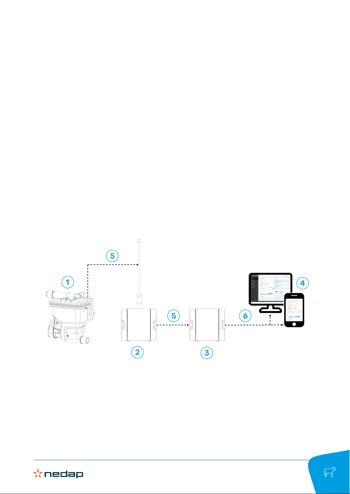
Figure1:SmartFlow system overview
1. SmartFlow with Float 4. PC or smartphone with performance insights in Velos
2. V-box with VP4102 UHF reader and antenna 5. UHF connection (CAN or Ethernet)
3. V-box with VP8002 VPU 6. Ethernet connection

Nedap SmartFlow / Installation manual
Version 00.001 / September 2020 / EN
6
Dairy Farming
Components
6
4
5
2
3
1
Figure2
1. Cover 4. Main volume
2. Spreader plate 5. Valve module
3. Float 6. Mounting bracket
1. The cover with the inlet ensures a continuous milk and air flow.
2. The spreader plate spreads the milk and air into the main volume for a free milk and air flow.
3. The Float measures the milk yield and milking process.
4. The main volume collects the milk and ensures a free air flow during milking.
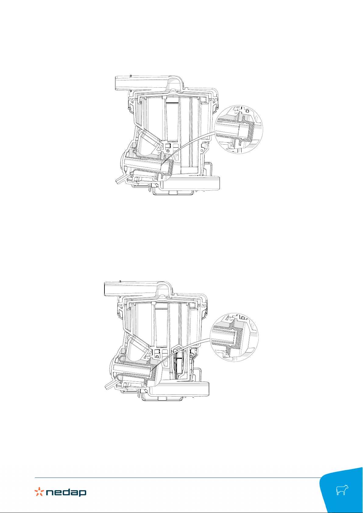
5. The valve module makes sure the milk or cleaning fluid flows through the SmartFlow. The valve has 2
positions:
Nedap SmartFlow / Installation manual
Version 00.001 / September 2020 / EN
7
Dairy Farming
a. Milking mode.
When the valve is in the milking position, the milk cannot flow away from the right side of the valve.
The milk level in the main volume rises, and the Float starts floating on the milk flow, and measures the
amount of milk in the SmartFlow.
b. Cleaning mode.
When the valve is in the cleaning position, only a bit of the liquid can flow through the flow column. This
will completely fill the rest of the SmartFlow with cleaning liquid, which ensures proper cleaning of the
SmartFlow.

Nedap SmartFlow / Installation manual
Version 00.001 / September 2020 / EN
8
Dairy Farming
6. The mounting bracket ensures the SmartFlow can be mounted firmly to the wall.

Nedap SmartFlow / Installation manual
Version 00.001 / September 2020 / EN
9
Dairy Farming
3 Installation
Do not operate the product without first reading this chapter and the safety section at the beginning of this
manual.
Warning
Failure to follow safety precautions in this chapter could result in serious injury or death.
3.1 Requirements for installation
3.1.1 Electrical requirements
Mains power
Make sure the mains power supply for the system is easily accessible and not too far away from the barn
in which the units are placed. The power sockets shall be installed near the equipment and must be easily
accessible.
Caution
Nedap power supplies must be connected to a power socket with protective earth (PE). Always use a 3-pole
connector with a PE contact.
If there is no PE available, create a PE next to the power socket to be used for each power supply. The
properties of a correct PE depend on local circumstances and legislation. Always comply with local rules and
regulations when installing earth electrodes.
Network
Use a fiberglass network between the VPUs (VP8002) if
• the power supplies have different power sources with a separate PE;
• the distance between two VPUs or the distance between one VPU and a router/switch exceeds 100 m (330
ft.);
• there is often lightning in the area.
Cabling
Install Velos CAN cable(s) and Ethernet cable(s) inside a plastic (PVC) conduit.
• Do NOT install cables directly to metal ceiling, trusses and feed lines.
• Install fiberglass cables inside a plastic (PVC) conduit with an inner diameter of at least Ø 25 mm (1 in.).
Surge protection and UPS
Caution
Always use surge protectors with Ethernet surge protection.
Install an Uninterruptible Power Supply (UPS) that is connected to the VP2001 when the power source is not
reliable and constant. The UPS is intended to correctly power down the VP8002 and will also run the other V-
packs in the Nedap system for a brief period.
The VP8002 has internal backup power that will shut down the VP8002 correctly when the power is
interrupted. The internal backup power will not run the other V-packs in the Nedap system.

Nedap SmartFlow / Installation manual
Version 00.001 / September 2020 / EN
10
Dairy Farming
Lightning protection
It is important to follow closely the guidelines that are described in this section, in order to minimize risk of
damage on Velos systems in case of lightning. Nedap does, however, not accept any responsibility for damage
caused by high voltage (such as lightning), as described in the Warranty Policy.
Protective Earth (PE)
PE is meant for safety related issues such as electric shocks to humans or animals. PE will not protect devices
(sufficiently) when they are struck by lightning. Normally PE is situated next to the main power source only.
Grounding
Grounding is a connection to the ground, but not Protective Earth, for example a metal roof that is connected to
different earth electrodes in order to lead high peak currents (such as lightning) to the earth.
3.1.2 Network requirements
Basic network requirements
• Router to connect the VPU (VP8002) to the Internet.
• Use of DHCP (Dynamic Host Configuration Protocol) advised.
• LAN Ethernet cable UTP minimum cat 5.
• Minimum upload speed: 1 MB/s
Wi-Fi requirements
To experience all the benefits of the Nedap system, a full covering Wi-Fi installation is crucial in the area
where the system is applied. A functional Wi-Fi connection offers easy access to the mobile interface, allowing
operation by smartphone or tablet. Because of the wide variation in barn designs, we recommend to make use of
local Wi-Fi specialists to plan, install and service such a Wi-Fi installation.
In order to install single wireless networks, we advise you to consider the following conditions. These conditions
are set up for a so-called single wireless network.
General recommendations regarding setting up a Wi-Fi installation
• Always follow local circumstances and legislation regarding wireless network configurations.
• Never use powerful Wi-Fi transmitters; powerful transmitters will generate more noise.
• Do not use dual band or the 5 GHz band; only use the 2,4 GHz band.
• Never use (multiple) ordinary consumer electronics Wi-Fi routers.
• Only use professional access points to create a wireless network.
• Only use a single wireless network configuration, also called "roaming network".
• Use splash and dust proof plastic housings (IP65) to install professional access points.
Wi-Fi bridge requirements for point-to-point connection
• 5GHz to minimize interference (recommended 5.18GHz ~ 5.825GHz).
• High-Power Output to ensure long distance coverage.
• Connection rate of 300 Mbps or higher.
• Internal High-Gain Directional Antenna (10 dBi to 13 dBi or higher).
• Supports WPA2 Wi-Fi Security.
Nedap can never be kept responsible for incorrect functioning of networks or any damage arising from the
recommendations mentioned in this document.
3.1.3 Electromagnetic requirements
Nedap Animal Identification uses radio waves in compliance with ISO 11784/11785 standard and local
regulations.

Nedap SmartFlow / Installation manual
Version 00.001 / September 2020 / EN
11
Dairy Farming
Notwithstanding all due precaution by Nedap, Nedap Animal Identification may not function optimally due
to devices that emit radio waves, such as (but not limited to) variable frequency drives, electronic ballasts of
lighting systems, power supplies, electronic converters of solar panels/windmills and (long) wave radio stations,
which may cause interference with Nedap Animal Identification.
No claims, representations or warranties, whether expressed or implied, are made by Nedap as to the
performance, reliability, durability and safety of Nedap Animal Identification used in conjunction with
abovementioned or other devices.
In order to achieve optimal performance of Nedap Animal Identification, the electrical installation on the farm
needs to meet the conditions that are shown below.
• Maximum allowed environmental noise level: 10 dBµA/m quasi peak, according to CISPR 16-1-1.
• Maximum allowed conducted noise: according to EN55032: 2015.
3.2 Installation overview
Assemble and install the system according to the steps below. Each step will be fully explained in the next
sections.
1. Mount the SmartFlow (page 11).
2. Configure the Velos software (page 23).
3. Calibrate and validate the SmartFlow (page 23).
The SmartFlow can be mounted in two configurations: The milk outlet is positioned either on the right side or
the left side of the Smartflow. The mounting procedure only shows illustrations of the right side configuration,
but is applicable for the left side configuration as well.
Figure3:Right and left side configuration of the milk outlet on the SmarttFlow
The installation of the VP8002 VPU and VP4102 UHF reader with antenna is described in the installation
manuals of these products. This documentation can be obtained from your dealer or on our Business portal:
http://www.nedap.com/livestockmanagement-portal.
3.3 Mount the components
3.3.1 Mount the SmartFlow
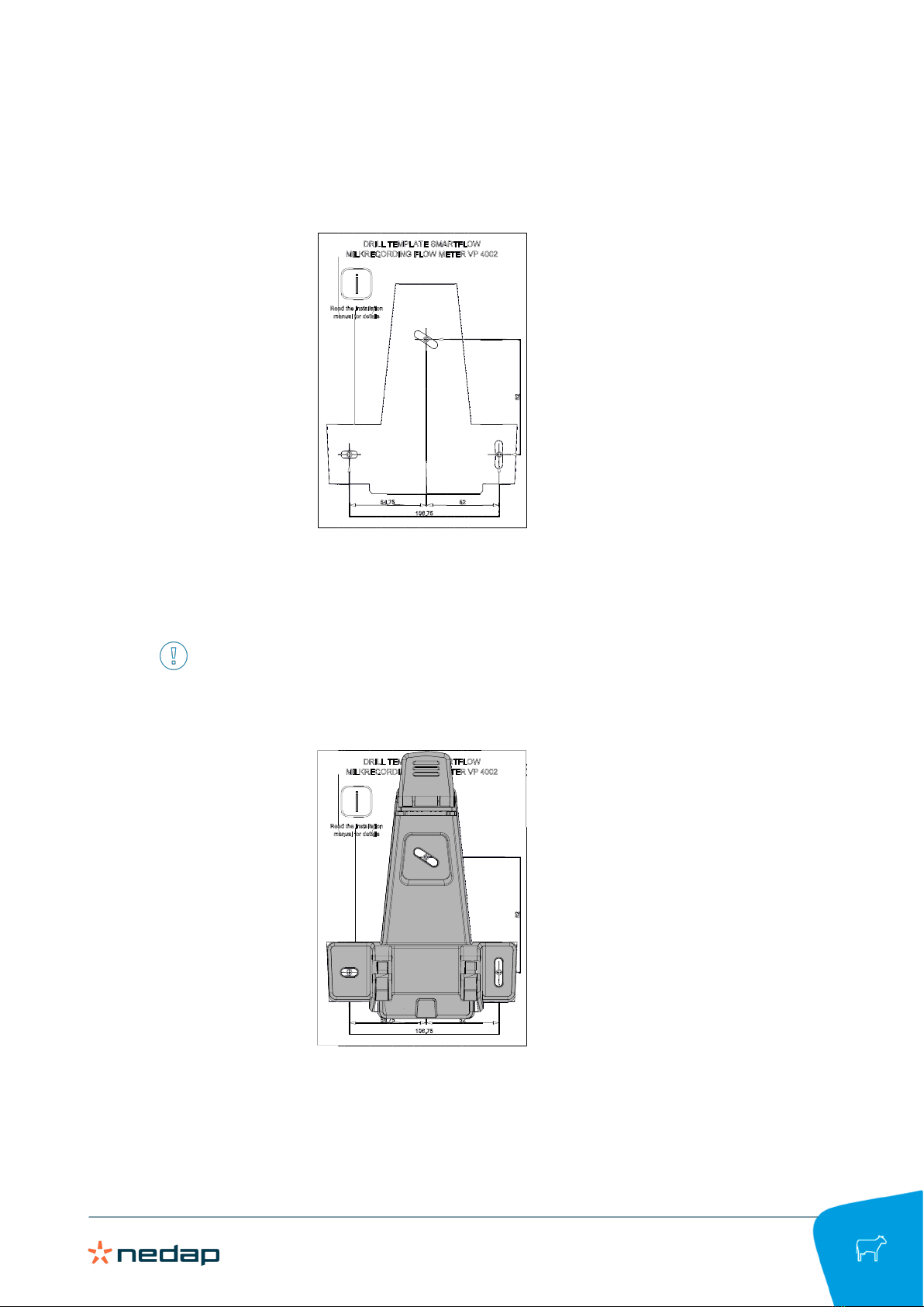
1. Mount the bracket on a flat surface, for example a wall or a plate. Use appropriate mounting material.
Make sure there is at least 10 cm free space above the bracket.
Nedap SmartFlow / Installation manual
Version 00.001 / September 2020 / EN
12
Dairy Farming
a. Use the drilling template that is delivered with the SmartFlow to mark 3 drilling holes on the wall or
panel.
b. Drill the holes.
c. Mount the bracket using 3 hex bold screws or hex head lag wood screws (M5, at least 20 mm length)
with washers.
Tighten the 2 lower screws hand-tight. These screws are used to level the SmartFlow.

Nedap SmartFlow / Installation manual
Version 00.001 / September 2020 / EN
13
Dairy Farming
d. Use the two lower screws of the bracket to level the bracket in the sidewards direction (left or right).
e. Tighten the 2 lower screws to lock the bracket. The correct tightening moment for the bolt is xx Nm (xx
lbf·ft.)
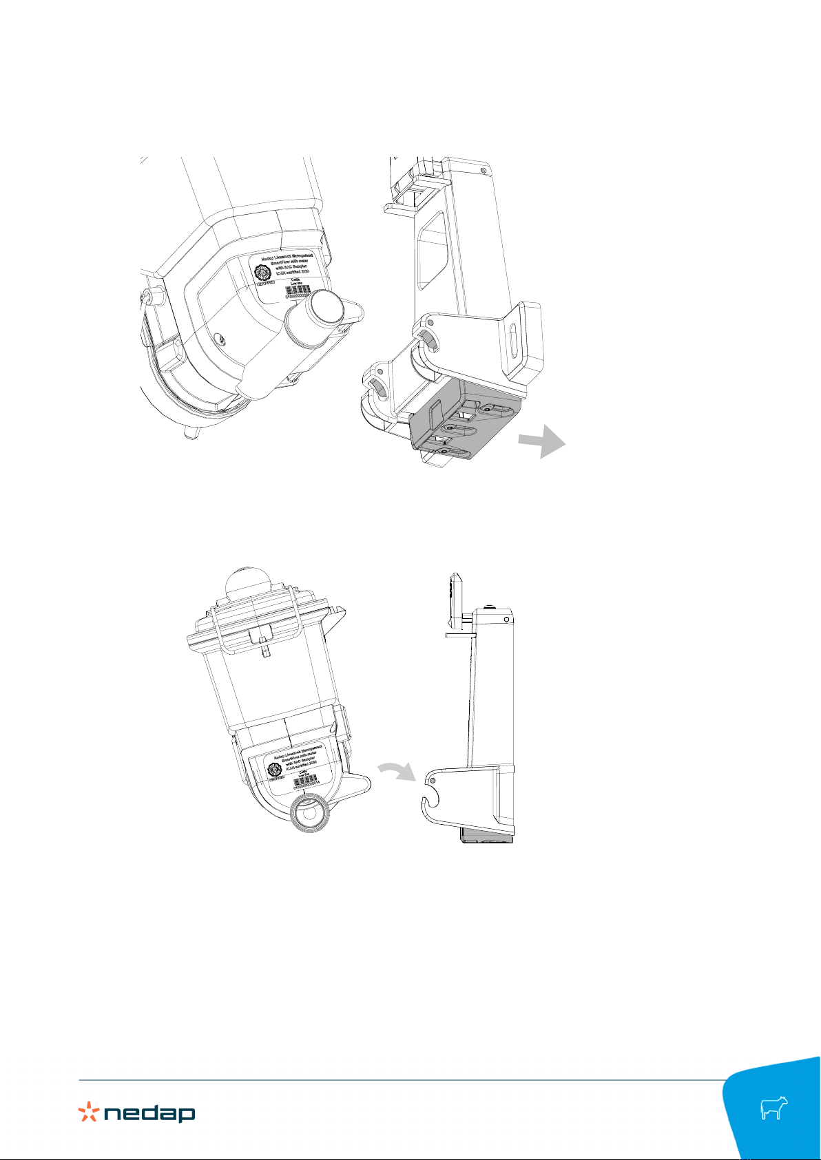
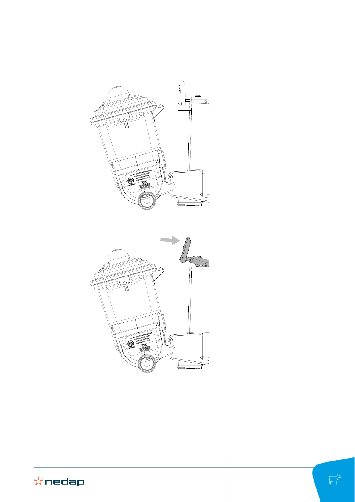
2. Place the SmartFlow in the bracket as follows:
Nedap SmartFlow / Installation manual
Version 00.001 / September 2020 / EN
14
Dairy Farming
a. Press the push button at the bottom of he bracket backwards to open the hinges.
b. Slide the lower part of the SmartFlow in the hinges and release the push button.
Nedap SmartFlow / Installation manual
Version 00.001 / September 2020 / EN
15
Dairy Farming
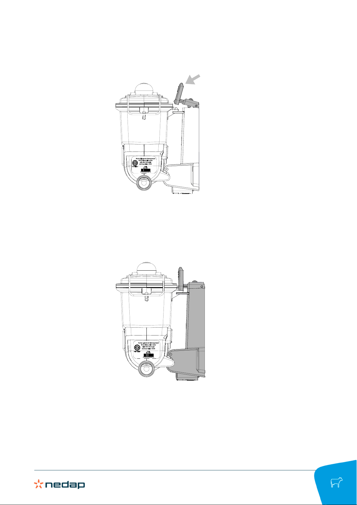
c. The hinges are closed and the lower part of the SmartFlow is now fixed in the bracket.
d. Press the lever at the top of the bracket and slide the ridge of the SmartFlow under the lever.
Nedap SmartFlow / Installation manual
Version 00.001 / September 2020 / EN
16
Dairy Farming
e. Release the lever to snap the upper part the SmartFlow.
The SmartFlow is now mounted firmly in the bracket.
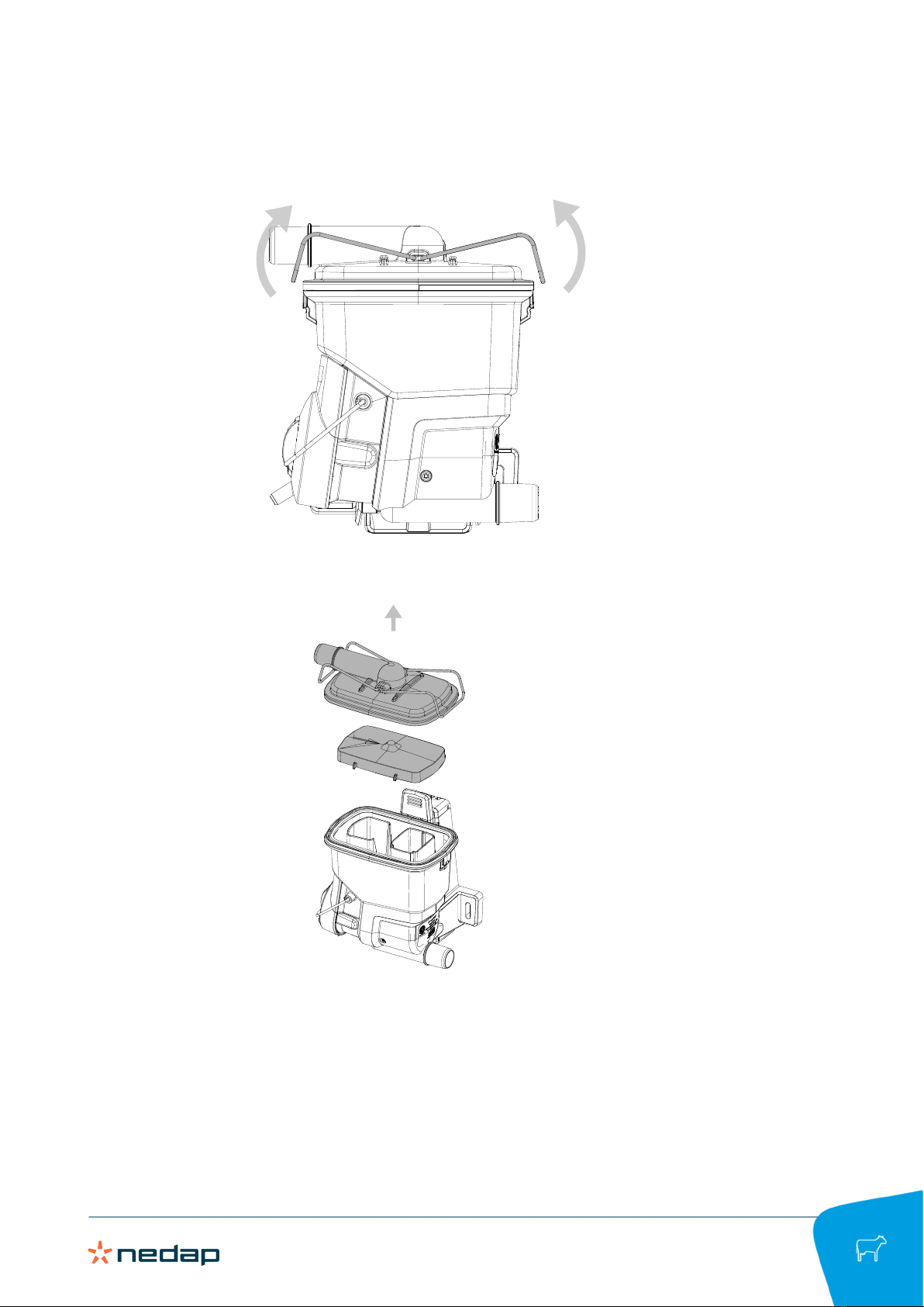
3. Level the bracket in forward-backward direction:
Nedap SmartFlow / Installation manual
Version 00.001 / September 2020 / EN
17
Dairy Farming
a. Loosen the cover brackets of the SmartFlow.
b. Remove the cover and spreader plate.

Nedap SmartFlow / Installation manual
Version 00.001 / September 2020 / EN
18
Dairy Farming
4. Use the screw on top of SmartFlow to level the bracket in the forward-backward direction.
3.3.2 Prepare the Float
When the SmartFlow has been mounted, the next step is to prepare the float and attach the milk and vacuum
tubes to the SmartFlow:
1. Unpack the Float.
Other manuals for SmartFlow
2
Table of contents
Other Nedap Farm Equipment manuals


