User manual
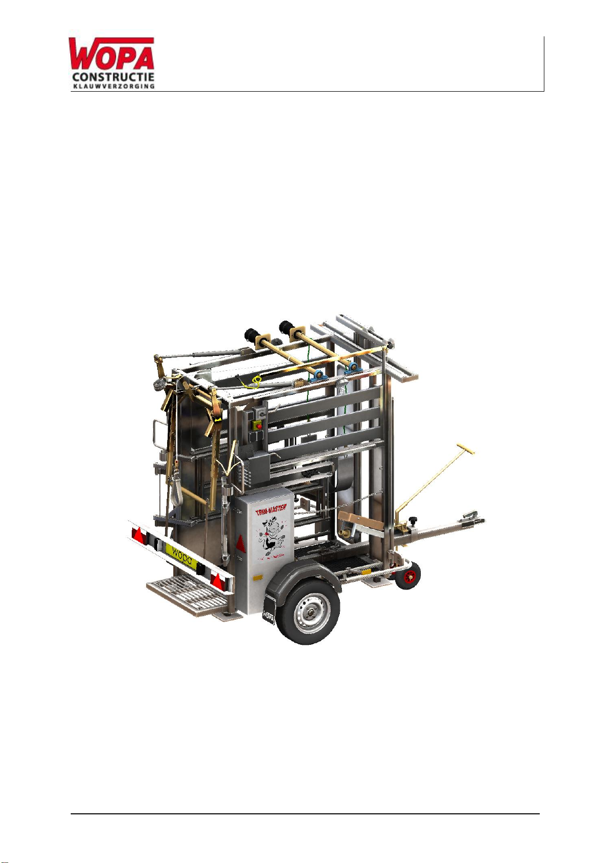
Hoof trimmingcrush:SA0049
Version: 22-12-15
Page 5 of 31
Table of Contents
INTRODUCTION..................................................................................................................................................... 3
WARRANTY............................................................................................................................................................ 4
TABLE OF CONTENTS.......................................................................................................................................... 5
EC CONFORMITY DECLARATION (COPY).......................................................................................................... 6
OVERVIEW OF SYMBOLS..................................................................................................................................... 7
PICTOGRAMS ........................................................................................................................................................ 8
1. TECHNICAL INFORMATION........................................................................................................................ 10
2. DESCRIPTION OF THE INSTALLATION..................................................................................................... 11
2.1. DESCRIPTION OF THE MAIN COMPONENTS SA0049.................................................................... 11
2.2. ELECTRICAL INSTALLATION ....................................................................................................... 14
2.3. HYDRAULIC INSTALLATION ........................................................................................................ 15
3. SAFETY ........................................................................................................................................................ 16
3.1. GENERAL................................................................................................................................. 16
3.2. DURING NORMAL USE ............................................................................................................... 17
3.3. OPERATING PERSONNEL........................................................................................................... 17
4. INSTALLATION ............................................................................................................................................ 18
4.1. LOCATION................................................................................................................................ 18
4.2. CONNECT THE MACHINE. .......................................................................................................... 20
4.3. PREPARING FOR TRANSPORTATION........................................................................................... 20
5. OPERATION ................................................................................................................................................. 21
5.1. STARTING UP........................................................................................................................... 21
5.2. EMERGENCY STOP................................................................................................................... 21
5.3. PRODUCTION........................................................................................................................... 22
5.4. HOOK UP THE FRONT LEG......................................................................................................... 23
6. MAINTENANCE............................................................................................................................................ 24
6.1. MAINTENANCE DIAGRAM........................................................................................................... 24
6.2. CLEAN THE MACHINE................................................................................................................ 26
6.3. LUBRICATION OF REAR GATE..................................................................................................... 26
6.4. CHECK OIL LEVEL/REPLACE OIL................................................................................................. 27
6.5. CHECK PLAY IN THE WHEELS..................................................................................................... 28
6.6. CHECK THE SHAFT BOLTS......................................................................................................... 28
6.7. PARTS..................................................................................................................................... 28
7. DISPOSAL AS WASTE ................................................................................................................................ 29
8. APPENDIX .................................................................................................................................................... 30
8.1. LOGBOOK ................................................................................................................................ 30
LIJST MET AFBEELDINGEN
FIGURE 1OVERVIEW SA0049.................................................................................................................. 12
FIGURE 2OVERVIEW OF THE HYDRAULIC INSTALLATION.............................................................................. 15
FIGURE 3DETAILS OF CONVERSION FROM TRANSPORT SET-UP TO WORKING SET-UP (SA0049) ................... 18
FIGURE 4: DETAIL OF HOOKING UP FRONT LEG ........................................................................................... 23
FIGURE 5: LUBRICATION OF REAR GATE..................................................................................................... 26
FIGURE 6: HYDRAULIC FLUIDS TO BE USED................................................................................................. 27
FIGURE 7: DETAILS OF SHAFT BOLT TORQUE SETTINGS .............................................................................. 28