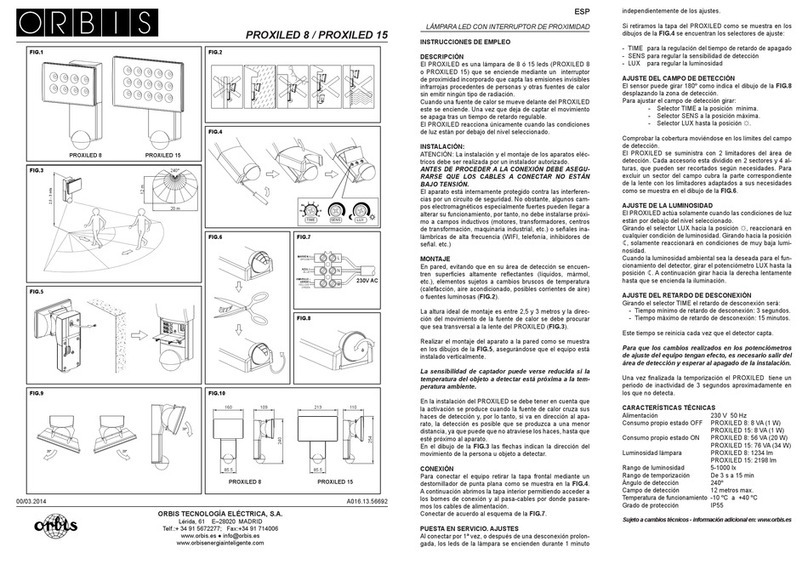
NERI LIGHT 31 Series User manual

1
www. neri.biz
I
GB
F
D
E
Rev. A - 08/2012
ATTENZIONE - CAUTION
ATTENTION - ACHTUNG
ATENCIÓN
Questo manuale va letto
e conservato con molta attenzione
This manual should be read with
attention and kept with great care
Ce manuel doit être lu très
attentivement et soigneusement
conservé
Die Anleitung sollte mit großer
Aufmerksamkeit gelesen und
aufbewahrt werden
Este manual se debe leer con
detenimiento y conservar
cuidadosamente
LIBRETTO ISTRUZIONI
APPARECCHI
DI ILLUMINAZIONE
INSTRUCTION BOOKLET
LIGHT FIXTURES
NOTICE DE MONTAGE
LUMINAIRES
INSTALLATIONSANLEITUNG
BELEUCHTUNGSAPPARATE
MANUAL DE
INSTRUCCIONES DE
DISPOSITIVOS DE
ALUMBRADO
I
GB
F
D
E
LIGHT 31
for discharge lamps

2 3
Autori: Antonio e Domenico Neri - Titolo: Libretto Istruzioni Apparecchi di Illuminazione - Pubblicatore: Neri spa
Progetto e coordinamento graco: Daniele Lombardi - Stampa: Grache MDM Srl, Forlì FC, Agosto 2012.
Tutti i diritti riservati. E’ fatto espresso divieto a qualunque riproduzione parziale o totale del presente testo.
© 2012, DESIGN PATENTED, PRINTED IN ITALY
Questo manuale è soggetto a copyright © 2012. Tutti i diritti sono riservati.
E’ vietata la riproduzione anche parziale di esso senza il consenso scritto della Neri spa.
La Neri spa si riserva il diritto di apportare modiche ai propri prodotti e alla documentazione senza obligo di preavviso.
This manual is subject to copyright © 2012. All rights reserved.
Reproduction of this manual, even partially, is forbidden without written consent from Neri spa.
Neri spa reserves the right to modify its products and documentation without obligation to give prior warning.
Ce manuel fait l’objet d’un copyright © 2012. Tous droits réservés.
Ce manuel ne peut être reproduit, même partiellement, sans l’accord écrit de Neri spa.
Neri spa se réserve le droit d’apporter toutes modications à ses produits et à la documentation sans préavis.
Dieses Handbuch unterliegt dem Copyright © 2012. Alle Rechte vorbehalten.
Seine - auch auszugsweise - Reproduktion ohne schriftliche Zustimmung der Neri spa ist verboten.
Die Neri spa behält sich das Recht vor, an ihren Produkten und der Dokumentation Veränderungen vorzunehmen,
ohne dies vorher ankündigen zu müssen.
Este manual está protegido por derechos de la propiedad intelectual © 2012. Reservados todos los derechos
Se prohibe la reproducción incluso parcial del mismo sin el permiso por escrito de la empresa Neri spa.
La empresa Neri spa se reserva el derecho de aportar cambios a los propios productos y a la documentación
sin obligación de aviso previo.
NERI spa
S.S. Emilia 1622 - 47020 Longiano (FC) - Italy
Tel. +39 0547 652111 Fax +39 0547 54074
Certicato/Certicate
9105.DONE
ISO 9001:2008
Certicato/Certicate
9191.NER1
ISO 14001:2004

3
www. neri.biz
INDICE - CONTENTS - INDEX - INHALTVERZEICHNIS - INDICE
SIMBOLI E ETICHETTA
SYMBOLS AND LABEL
SYMBOLES ET ETIQUETTE
SYMBOLE UND AUFKLEBER
SÍMBOLOS Y ETIQUETAS
pag 4
1°
NOTE ALLA CONSEGNA
DELIVERY INFORMATION
NOTES POUR LA LIVRAISON
ANMERKUNGEN ZUR ANLIEFERUNG
NOTAS A LA ENTREGA
pag 5-7
2°
PRESCRIZIONI DI SICUREZZA
SAFETY PRECAUTIONS
PRESCRIPTIONS DE SECURITE
SICHERHEITSVORSCHRIFTEN
NORMAS DE SEGURIDAD
pag 8
3°
DISIMBALLO
UNPACKING
DEBALLAGE
AUSPACKEN
DESEMBALAJE
pag 9
4°
DESTINAZIONE D’USO
INTENDED USE
UTILISATION DES LUMINAIRES
ZWECKBESTIMMUNG
UTILIZACIÓN
pag 22
10°
MANUTENZIONE
MAINTENANCE
ENTRETIEN
WARTUNG
MANTENIMIENTO
pag 24
13°
SOSTITUZIONE FUSIBILE
FUSE REPLACEMENT
REPLACEMENT DU FUSIBILE
AUSTAUSCH DER SICHERUNG
SUSTITUCIÓN FUSIBLES
pag 25
14°
ORIENTAMENTO OTTICA ASIMMETRICA
ASYMMETRICAL REFLECTOR POSITIONING
ORIENTATION DU RÉFLECTEUR ASYMÉTRIQUE
ASYMETRISCHER REFLEKTOR AUSRIGHTUNG
ORIENTACIÓN DEL REFLECTOR ASIMÉTRICO
pag 27
16°
GARANZIA
GARANTEE
GARANTIE
GARANTIE
GARANTIA
pag 23
12°
AVVERTENZE PER L’INSTALLAZIONE
INSTALLATION INFORMATION
PRECAUTION POUR L’INSTALLATION
INSTALLATIONSANLEITUNG
ADVERTENCIAS PARA INSTALACI
Ó
N
pag 20-21
9°
CARATTERISTICHE
CHARACTERISTICS
CARACTERISTIQUES
EIGENSCHAFTEN
CARACTERÍSTICAS
pag 18
7°
pag 10-13
5°
INSTALLAZIONE APPARECCHI A SOSPENSIONE
INSTALLATION OF SUSPENDED FIXTURES
INSTALLATION DES LUMINAIRES SUSPENDUS
HÄNGENDE APPARATE
INSTALACIÓN DE DISPOSITIVOS SUSPENDIDOS
pag 14-17
6°
INSTALLAZIONE APPARECCHI PORTATI
INSTALLATION OF UPRIGHT FIXTURES
INSTALLATION DES LUMINAIRES SUPPORTES
AUFGESETZTE APPARATE
INSTALACIÓN DE DISPOSITIVOS APOYADOS
TABELLA RIASSUNTIVA DATI
SUMMARY OF DATA
TABLEAU RECAPITULATIF DES DONNEES
TECHNISCHE DATEN
RESUMEN DE DATOS UTILIZACIÓN
pag 19
8°
PARTI DI RICAMBIO
SPARE PARTS
PIÈCES DE RECHANGE
ERSATZTEILE
PIEZAS DE REPUESTO
pag 26
15°
SMALTIMENTO
DISPOSAL
MISE AU REBUT
ENTSORGUNG
RECICLADO
pag 22
11°

4 5
INTRODUZIONE - INTRODUCTION - INTRODUCTION - EINLEITUNG - INTRODUCCIÓN
La Neri spa è impegnata costantemente nella ricerca e progettazione di prodotti di alta qualità, lunga durata e sicurezza.
Questo manuale intende presentare le metodiche di installazione, uso e manutenzione corrette, ponendosi come guida
nei confronti di installatori professionali. A tale scopo questo manuale va letto e conservato con molta attenzione.
Neri spa is constantly committed to research and design for products of high quality, durability and safety. This manual
aims to present correct methods of installation, use and maintenance, as a guide for professional installers. This manual
should be read and kept with great care.
Neri spa a toujours eu pour objectif la recherche et la conception de produits de haute qualité, offrant longévité et sécu-
rité. Ce manuel, qui présente les modes d’installation, d’utilisation et d’entretien corrects des luminaires, est un guide à
l’adresse des installateurs professionnels. Il doit donc être lu très attentivement et soigneusement conservé.
Die Neri spa ist andauernd mit der Forschung und Entwicklung von qualitativ hochstehenden, langlebigen und sicher-
en Produkten beschäftigt. Diese Anleitung will die korrekten Methoden der Installation, des Einsatzes und der War-
tung vorstellen und sieht sich dabei als Führer hinsichtlich professioneller Installateure. Die Anleitung sollte mit großer
Aufmerksamkeit gelesen und aufbewahrt werden.
La empresa Neri spa trabaja de continuo en el estudio y proyección de productos de alta calidad, de larga duración y
seguri-dad. Este manual presentará los métodos de instalación, uso y mantenimiento correctos, siendo una guía para
instaladores profesionales. Por ello, este manual se debe leer con detenimiento y conservar cuidadosamente.
NOTE GENERALI ALLA CONSEGNA - DELIVERY INFORMATION
NOTES GENERALES POUR LA LIVRAISON - ALLGEMEINE ANMERKUNGEN ZUR ANLIEFERUNG
NOTAS GENERALES A LA ENTREGA
1°
Gli apparecchi per illuminazione sono spediti esclusivamente in scatole di cartone (A) in varie dimensioni.
In ogni caso comunque al ricevimento della merce controllare che:
1) l’imballo sia integro; 2) la fornitura corrisponda all’ordine (vedi bolla di consegna); 3) non vi siano parti mancanti o
danneggiate. In questi casi, informare immediatamente e in modo dettagliato (e/o con foto) la Neri spa.
The light xture is shipped and delivered only in cardboard boxes (A) of various sizes.
On receipt of the goods, always:
1) check that packing is undamaged; 2) check that goods received correspond to order (consult delivery note); 3) check
that there are no missing parts. In this case, immediately inform Neri spa, giving full details (and/or with pho-tograph).
Les luminaires ne peuvent être expédiés qu’emballés dans des boîtes en carton (A) de dimensions diverses. Quoi qu’il
en soit, dès la réception de la marchandise, s’assurer que:
1) l’emballage soit intact; 2) la fourniture corresponde à la commande (voir bulletin de livraison); 3) il ne manque aucune
partie. En cas de dommages ou de parties manquantes, en informer immédiatement d’une manière détaillée (et/ou avec
photo) Neri spa.
Die Beleuchtungsapparate werden ausschließlich in Pappkartons (A) unterschiedlicher Größe versandt Jedenfalls muss
man beim Wareneingang stets kontrollieren, dass:
1) die Verpackung unversehrt ist; 2) die Lieferung der Bestellung entspricht (siehe Lieferschein); 3) keine Teile fehlen.
Bei Schäden oder fehlenden Teilen sofort und detailliert (u./o. mit Foto) die Neri spa informieren.
Los aparatos de alumbrado se pueden enviar sólo en cajas de cartón (A) de varios tamaños. De todos modos al recibir
la mercancía controlen:
1) que el embalaje esté íntegro; 2) que el suministro corresponda al pedido (vean albarán); 3) que no falten piezas.
En caso de daños o piezas que falten, informen a Neri spa de inmediato y con detalles (y/o con foto).
A

5
www. neri.biz
Fig. 1 Fig. 2
Fig. 4 Fig. 6
Fig. 3
Fig. 5
I simboli raffigurati sopra hanno il seguente significato:
Fig 1 > NOTA INFORMATIVA - Fig 2 > VERIFICA TECNICA - Fig 3 > PERICOLO - Fig 4 > CASCO OBLIGATORIO,
Fig 5 > SCARPE ANTINFORTUNISTICHE, Fig 6 > GUANTI DA LAVORO.
Ogni apparecchio è contrassegnato da una etichetta adesiva posta sull’imballo. Vi sono riportati il codice e la descrizione,
due dati basilari con cui è possibile identificarlo.
The symbols shown above have the following meanings:
Fig. 1 > INFORMATIVE NOTE - Fig. 2 > TECHNICAL CHECK - Fig. 3 > DANGER
Fig. 4 > SAFETY HELMET COMPULSORY - Fig. 5 > SAFETY FOOTWEAR - Fig. 6 > WORK GLOVES.
Every light fixture is marked with a sticker on the packing. This shows the code and the description, the two essential
items of information for identification.
Les symboles indiqués ci-dessus correspondent aux significations suivantes:
Fig 1 > NOTE INFORMATIVE - Fig 2 VERIFICATION TECHNIQUE - Fig 3 > DANGER
Fig 4 > CASQUE OBLIGATOIRE - Fig 5 > CHAUSSURES DE SECURITE - Fig 6 > GANTS DE TRAVAIL.
Tous les éléments portent une étiquette adhésive placée sur l’emballage. Sur cette étiquette figurent le code et la
description, deux données fondamentales pour leur identification.
Die oben gezeigten Symbole haben folgende Bedeutung:
Fig 1> INFORMATIVE ANMERKUNG - Fig 2 > TECHNISCHE ÜBERPRÜFUNG - Fig 3 > GEFAHR
Fig 4 > HELMPFLICHT - Fig 5 > UNFALLSICHERE SCHUHE - Fig 6 > ARBEITSHANDSCHUHE.
Jedes Element ist durch einen Aufkleber auf der Verpackung gekennzeichnett. Darauf befinden sich der Code und die
Beschreibung, zwei Basisdaten, durch die man es identifizieren kann.
Los símbolos mostrados arriba tienen el siguiente significado:
Fig 1 > NOTA INFORMATIVA - Fig 2 > COMPROBACIÓN TÉCNICA - Fig 3 > PELIGRO
Fig 4 > CASCO OBLIGATORIO - Fig 5 > CALZADO ESPECIAL DE TRABAJO - Fig 6 > GUANTES DE TRABAJO.
Cada elemento está marcado con una etiqueta adhesiva colocada sobre el embalaje. Aparecen allí el código y la
descripción, dos datos básicos con que se pueden identificar.
SIMBOLI / ETICHETTA - SYMBOLS AND LABEL- SYMBOLES ET ETIQUETTE
SYMBOLE UND AUFKLEBER - SÍMBOLOS Y ETIQUETAS
2°
Code: SQ310A0943513
LA.SO.210 AL.PMMA. GHIT. OTT4
ST150W E40 CL2AUT

6 7
Il corretto orientamento degli apparecchi si ottiene posizionando l’apparecchio con l’ottica perpendicolare alla carreggiata,
con il portalampada dal lato del centro della carreggiata. Di conseguenza la punta della lampada sarà rivolta verso il
marciapiede (vedi schema g. C). Il questo caso il usso luminoso emesso sulla carreggiata sarà ottimale. In caso contrario,
l’apparecchio dovrà essere riorientato.
The correct alignment for light xtures is obtained by positioning the xture with the reector perpendicular to the roadway
and the lamp-holder towards the centre of the road. The tip of the lamp will therefore point towards the pavement side
(see g. C). In this case optimal light emission on the roadway will be ensured. If necessary, the light xture must be rotated
to obtain correct alignment.
Etichette adesive di avvertimento e indicazione sono poste sull’apparecchio e l’installatore deve scrupolosamente
seguirne le indicazioni. Vi possono essere indicazioni sul posizionamento dell’apparecchio rispetto alla carreggiata stradale
(fig.A), richiami di attenzione sulle caratteristiche della lampada da installare o sostituire (fig. B) o altre indicazioni di particolare
importanza.
Stickers with warnings and instructions are applied to the light fixture, and the installer must comply scrupulously with
the information given. The information given may include instructions on the positioning of the light fixture with respect to the
roadway (fig. A), indications on the characteristics of the lamp to be fitted or replaced (fig. B) or other instructions of particular
importance.
L’installateur doit respecter scrupuleusement les indications et les avertissements figurant sur les étiquettes adhésives
placées sur l’appareil. Celles-ci peuvent contenir des indications sur le positionnement de l’appareil par rapport à la chaussée
(fig. A), sur les caractéristiques des lampes à installer ou à remplacer (fig. B) ou d’autres informations importantes.
Auf dem Apparat befinden sich Aufkleber mit Hinweisen und Vorsichtsmaßregeln, und der Installateur muss den Hinweisen
gewissenhaft folgen. Es kann sich um Hinweise zur Positionierung des Apparates bezüglich der Fahrbahn (Abb. A)handeln,
Aufforderungen zur Beachtung der Charakteristiken der zu installierenden oder zu ersetzenden Lampe (Abb. B) oder andere
Hinweise von besonderer Wichtigkeit.
En el aparato aparecen colocadas etiquetas adhesivas con advertencias e indicaciones y el instalador las debe seguir
al pie de la letra.
Puede haber indicaciones referidas a la colocación del aparato con respecto al nivel de la calzada (fig A), avisos sobre las
características de la lámpara que se va a instalar o a substituir (fig. B) y otras indicaciones de especial importancia.
SIMBOLI / ETICHETTA - SYMBOLS AND LABEL- SYMBOLES ET ETIQUETTE
SYMBOLE UND AUFKLEBER - SÍMBOLOS Y ETIQUETAS
2°
ATTENZIONE
Accenditore con impulso di
innesco ..... KV.
Installare solo lampade
compatibili al tipo di impulso.
ATTENTION
Igniter with starting impulse
...... KV. Install only lamps
compatible with this impulse type.
B
A

7
www. neri.biz
SIMBOLI / ETICHETTA - SYMBOLS AND LABEL- SYMBOLES ET ETIQUETTE
SYMBOLE UND AUFKLEBER - SÍMBOLOS Y ETIQUETAS
2°
Pour obtenir une orientation correcte des luminaires placer le luminaire le réecteur perpendiculaire à la chaussée, la
douille devant ainsi se trouver du côté du centre de la chaussée. La pointe de la lampe sera consécutivement tournée
vers le trottoir (voir schéma g. C). De cette façon, la lumière émise sur la chaussée sera optimale. En cas contraire, le
luminaire devra être réorienté.
Die korrekte Ausrichtung der Apparate mit asymmetrischer Optik erreicht man, indem man den Apparat mit zur Fahrbahn
senkrechter Optik installiert, mit der Lampenfassung an der Seite zur Fahrbahnmitte; folglich wird der Lampenkopf
zum Fußweg gerichtet sein (siehe Schema Abb. C). In diesem Fall wird der Lichtuss auf die Fahrbahn optimal sein.
Widrigenfalls müsste der Apparat neu ausgerichtet werden.
La orientación correcta de los aparatos se obtiene colocando el aparato con la pantalla perpendicular a la calzada, con
el portalámpara hacia el lado central de la calzada. Por tanto, la punta de la lámpara estará vuelta hacia la acera (vean
el dibujo Fig. C). En este caso el ujo luminoso emitido sobre la calzada será óptimo. En caso contrario, el aparato deberá
ser reorientado.
C
LATO STRADA
ROAD SIDE
OK
Attacco portalampada
Lamp-holder
Fixation de la douille
Lampenfassungsanschluss
Conexión portalámpara
Lampada - Lamp
Lampe - Lampe
Lámpara
Ottica asimmetrica - Asymmetrical reector
- Réecteur asymétrique
Asymmetrische Optik - Pantalla protectora asimétrica

8 9
In base alle varie direttive in vigore nei vari paesi europei ed extraeuropei, nel luogo di lavoro devono essere rispettate
determinate regole. Le indicazioni di sicurezza non hanno lo scopo di alterare o modificare le direttive sopra menzionate;
il loro unico scopo è quello di sottolinearle o amplificarle. Queste prescrizioni di sicurezza sono indirizzate agli installatori
professionali, i quali devono attentamente leggere e comprendere questo manuale.
La non osservanza delle prescrizioni citate in questo manuale aumenta il rischio di incidenti.
Prima di effetuare qualsiasi operazione munirsi di: casco antiurto, guanti da lavoro, scarpe antifortunistiche,
abbigliamento da lavoro.
A variety of rules must be followed in workplaces, depending on the legislation applicable in different countries of Europe
and elsewhere. The aim of the safety precautions illustrated here is not to replace or modify this applicable legislation,
but solely to emphasize or reinforce it. These safety precautions are intended for professional installers, who must
carefully read and understand this manual. Failure to apply the precautions illustrated in this manual will
increase the risk of accidents. Before carrying out any operations whatsoever installers must put on: safety helmets,
work gloves, safety footwear and suitable working clothes.
Conformément aux différentes directives en vigueur dans les pays européens et extra-européens, les lieux de travail
sont soumis à des règles précises qui doivent être respectées. Ces indications de sécurité n’entendent ni modifier ni
altérer les directives susdites mais ont pour but de les souligner ou d’en étendre l’application. Ces prescriptions de
sécurité s’adressent aux installateurs professionnels, qui devront lire attentivement ce manuel et en comprendre
parfaitement le contenu. La non-observation des prescriptions figurant dans ce manuel augmente le risque
d’accidents. Avant d’effectuer toute opération, s’équiper de: casque antichoc, gants de travail, chaussures de
sécurité, habillement de travail.
Auf Grundlage der verschiedenen in europäischen und außereuropäischen Ländern geltenden Vorschriften, müssen am
Ort der Arbeit bestimmte Regeln eingehalten werden. Die Sicherheitsangaben haben nicht den Sinn, die o.a. Vorschriften
zu verändern; ihr einziger Zweck ist es, sie zu unterstreichen oder zu erweitern. Diese Sicherheitsvorschriften wenden sich
an professionelle Installateure, die diese Anleitung aufmerksam lesen und begreifen müssen. Die Nichtbeachtung
der Vorschriften dieses Handbuchs erhöht das Unfallrisiko.
Vor der Durchführung von Arbeiten muss man sich eindecken mit: Schutzhelm, Arbeitshandschuhen, unfallsicheren
Schuhen, Arbeitsbekleidung.
De acuerdo con las diversas directivas en vigor en los países europeos y en los de fuera de Europa, en el lugar de
trabajo se deben respetar determinadas normas. Las normas de seguridad no tienen el objetivo de alterar o modificar
las directivas mencionadas anteriormente; el único objetivo es el de ponerlas en evidencia o ampliarlas. Estas normas
de seguridad se dirigen a los instaladores profesionales, los cuales deben leer atentamente y comprender
perfectamente este manual. El no observar las normas de seguridad citadas en este manual implica aumentar el
riesgo de accidentes. Antes de iniciar cualquier trabajo, pónganse: casco de seguridad, guantes de trabajo, calzado
especial de trabajo, ropa de trabajo.
ATTENZIONE - CAUTION
ATTENTION - ACHTUNG
ATENCIÓN
3°
PRESCRIZIONI DI SICUREZZA - SAFETY PRECAUTIONS - PRESCRIPTIONS DE
SECURITE - SICHERHEITSVORSCHRIFTEN - NORMAS DE SEGURIDAD

9
www. neri.biz
DISIMBALLO - UNPACKING - DEBALLAGE
AUSPACKEN - DESEMBALAJE
A
ATTENZIONE - CAUTION
ATTENTION - ACHTUNG
ATENCIÓN
Per il disimballo degli elementi comportarsi nel seguente modo:
1) predisporre a terra una robusta stuoia per proteggere le parti verniciate (fig. A); 2) non trascinare o rotolare gli elementi a
terra, ma porli sulla stuoia; 3) non usare taglierini o lame per togliere l’imballo (B), manualmente togliere il nastro adesivo
dagli imballi; 4) togliere i punti metallici dalle scatole (fig. C), attenzione a non disperderli nell’ambiente;
ATTENZIONE - La non osservanza delle prescrizioni citate sopra aumenta il rischio di incidenti.
ATTENZIONE - Non disperdere l’imballo nell’ambiente, potrebbe essere fonte di pericolo e inquinamento (fig. D).
Seguire le normali procedure di smaltimento dei rifiuti urbani in conformità alle norme vigenti.
To unpack, proceed as follows:
1) Lay a robust mat on ground to protect paintwork (fig. A). 2) Do not drag or roll elements on ground, but place on mat;
3) Do not use knives or other blades to remove packing materials, as this could damage paintwork (fig. B), but remove
adhesive tape from packing by hand. 4) Remove metal staples from cardboard boxes (fig. C), taking care to collect them
for correct disposal.
CAUTION - Failure to apply the above precautions will increase the risk of accidents.
CAUTION - Do not dispose incorrectly of packaging materials, which could be a source of pollution and danger (fig. D).
Follow normal waste disposal procedures for urban wastes in compliance with applicable legislation.
Pour le déballage des éléments, suivre les indications suivantes:
1) étendre sur le sol une natte robuste pour protéger les parties peintes (fig. A); 2) ne pas traîner ou faire rouler les éléments
sur le sol mais les placer sur la natte; 3) pour enlever l’emballage, ne pas utiliser de coupoirs ou de lames (fig. B), mais
ôter le ruban adhésif des emballages manuellement; 4) enlever les points métalliques des boîtes (fig. C), jeter ces derniers
dans un endroit approprié;
ATTENTION - La non-observation des prescriptions citées ci-dessus augmente le risque d’accidents.
ATTENTION - Déposer l’emballage dans un lieu de collecte approprié, pour éviter tout danger ou pollution de
l’environnement (fig. D).
Suivre les normales procédures de collecte des ordures urbaines conformément aux normes en vigueur.
Beim Auspacken der Elemente muss man wie folgt vorgehen:
1) auf dem Boden eine robuste Matte zum Schutz der lackierten Teile ausbreiten (
Abb.
A); 2) die Elemente nicht auf die
Erde ziehen oder rollen, sondern auf die Matte aufsetzen; 3) keine Schneidewerkzeuge zur Entfernung der Verpackung
benutzen, man könnte sonst die Lackierung beschädigen (
Abb.
B), die Klebefilme von Hand entfernen; 4) Die Metallstifte
der Kisten entfernen (
Abb.
C) und sie nicht in der Umgebung liegen lassen;
ACHTUNG - Die Nichtbeachtung dieser Anweisungen erhöht das Unfallrisiko.
ACHTUNG - Die Verpackung nicht in der Umgebung liegen lassen, sie könnte eine Gefahrenquelle sein und die Umwelt
verschmutzen (
Abb.
D). Folgen Sie den normalen Verfahren zur Beseitigung von städtischen Abfällen entsprechend
den geltenden Vorschriften.
Para desembalar los elementos compórtensen del siguiente modo:
1) Coloquen en el suelo una estera gruesa para proteger las partes pintadas (fig A); 2) No arrastren o hagan rodar los
elementos en el suelo, mas pónganlos sobre la estera; 3) No usen cuchillos o cuchillas para cortar el embalaje, pues
podrían raspar la pintura (fig C), retiren manualmente la cinta adhesiva de los embalajes;
4) Retirar las grapas de las cajas (Fig. C), atención a no dejarlas tiradas en el ambiente.
ATENCIÓN- El no observar las normas de seguridad citadas anteriormente implica aumentar el riesgo de accidentes.
ATENCIÓN- No dejen el embalaje tirado por ahí, podría resultar fuente de peligro o de contaminación (fig D).
Sigan el procedimiento normal de retirada de la basura urbana según las leyes vigentes.
4°
D
C
B

10 11
INSTALLAZIONE APPARECCHI A SOSPENSIONE - INSTALLATION OF SUSPENDED FIXTURES
INSTALLATION DES LUMINAIRES SUSPENDUS - HÄNGENDE APPARATE - INSTALACIÓN DE DISPOSITIVOS SUSPENDIDOS
SQ310A - SQ311A - SQ312A - SQ313A - SN310A - SN311A - SN312A - SN313A
5°
Accertarsi che l’apparecchio di illuminazione sia in perfetto stato e che la tensione
di funzionamento sia compatibile con la tensione di linea.
Avvitare l’apparecchio al sostegno no a mandarlo in battuta (g A). Nel caso
l’ottica non fosse orientata correttamente è necessario svitare leggermente
l’apparecchio per direzionarlo come indicato dall’etichetta posta sull’apparecchio
stesso (g B). Avvitare inne il grano di sicurezza (g C).
Seguire attentamente le istruzioni a pag. 7, che illustrano, come orientare
l’apparecchio nel modo corretto per ottenere le migliori prestazioni
illuminotecniche.
Check that the light xture is in perfect condition and that its operating voltage is
compatible with the power supply voltage.
Screw xture fully home onto support (g. A). If reector is not in correct direction,
slightly unscrew xture to reach direction indicated by sticker located directly on
xture (g. B). Finally tighten the safety grubscrew (g C). For correct positioning
of light xtures, carefully follow the instructions on pages 7, which describe
procedures to be followed to align the light xture so as to obtain optimal
lighting performance.
S’assurer que le luminaire soit en parfait état et que la tension de l’appareil soit
compatible avec la tension secteur.
Visser le luminaire à fond sur le support (g. A). Dans le cas où le réecteur ne soit
pas correctement orienté, dévisser légèrement le luminaire pour le placer dans la
position indiquée par l’étiquette placée sur le luminaire même (g. B). Enn, visser
la vis de sécurité (g C). Suivre attentivement les instructions des pages 7 qui
décrivent les procédures à suivre pour orienter l’appareil de façon à obtenir
les meilleures performances éclairagistes.
Versichern Sie sich, daß die Laterne unbeschädigt ist, und daß das Gerät mit
der Linienspannung vereinbar ist. Den Apparat bis zum Anschlag am Träger
festschrauben (Abb. A). Falls die Optik nicht korrekt orientiert sein sollte, muss
man den Apparat leicht losschrauben, um ihn, wie auf dem Etikett auf dem Apparat
selbst angegeben, auszurichten (Abb. B). Dann den Sicherungsstift einschrauben
(Abb C).
Zur korrekten Ausrichtung der Apparate mit asymmetrischer Optik
müssen die Anweisungen auf S. 7 genau befolgt werden; sie erläutern, wie
der Apparat so ausgerichtet wird, dass man beste beleuchtungstechnische
Leistungen erzielt.
Asegúrense de que el aparato esté en perfecto estado y que la tensión del mismo
sea compatible con la tensión de la línea eléctrica.
Atornillen el aparato al brazo de sujeción hasta el tope del tornillo (g A). En
caso de que el reector no esté correctamente orientado, hay que desatornillar
ligeramente el aparato para situarlo en la posición que indica la etiqueta situada
en el propio aparato (g B). Finalmente, atornillen el tornillo sin cabeza de
seguridad (g C).
Para la correcta orientación de los aparatos con pantalla reectora asimética
sigan atentamente las instrucciones de las páginas 7 que ilustran cómo
orientar el aparato de forma correcta para obtener las mejores prestaciones
luminotécnicas.
C
A
OK
B

11
www. neri.biz
INSTALLAZIONE APPARECCHI A SOSPENSIONE - INSTALLATION OF SUSPENDED FIXTURES
INSTALLATION DES LUMINAIRES SUSPENDUS - HÄNGENDE APPARATE - INSTALACIÓN DE DISPOSITIVOS SUSPENDIDOS
5°
SQ310A - SQ311A - SQ312A - SQ313A - SN310A - SN311A - SN312A - SN313A
Aprire, svitando le viti, la parte inferiore dell’apparecchio (g. D).
Disconnettere il giunto di collegamento della lampada (g. E). Estrarre, svitando
i pomelli, la piastra porta cablaggio (g. F). Estrarre dal sostegno circa 20 cm di
cavo (g. G), misurarne la quantità necessaria per l’innesto nei morsetti, spellare i
cavi collegandoli alla morsettiera, stringere in fermacavo (g. H).
Slacken and remove screws to open lower part of lantern (g. D)
Disconnect lamp power supply plug (g. E). Unscrew knobs and extract wiring
plate with plug (g. F). Extract about 20 cm of cable from the support (g. G).
Measure the length needed for connection to terminals. Strip wires and connect to
terminals. Secure with cable grip (g. H).
Ouvrir, après en avoir desserré les vis, la partie inférieure de l’appareil (g. D).
Débranchez le joint du raccordement de la lampe (g.
E
). Extraire, après en avoir dévissé
les pommeaux, la plaque de câblage (g.
F
). Extraire environ 20 cm de câble du support
(g. G), en mesurer la quantité nécessaire pour le branchement dans les bornes, mettre
les ls à nu et les relier à la boîte à bornes; serrer le collier de câble (g. H).
Den unteren Teil des Apparates öffnen, indem man die Schrauben löst (Abb. D).
Trennen Sie die Verbindung des Anschlußes der Lampe (Abb. E).
Die Verkabelungsplatte herausnehmen, indem man die Knäufe löst. (Abb. F).Etwa
20 cm Kabel aus der Halterung ziehen (Abb. G); die zum Einführen in die Klemmen
erforderliche Menge abmessen, die Kabel freilegen und an das Klemmbrett
anschließen; die Befestigungsklemmen festziehen (Abb. H).
Abran la parte inferior del aparato desatornillando los tornillos (g. D).
Desconecte el empalme de la conexión de la lámpara (g. E). Extraigan la placa
portaclables destornillando los pomos (g. F). Extraigan del soporte unos 20 cm
de cable (g. G), midan la longitud necesaria para acoplar en los bornes, pelen los
cables conectándolos al cuadro de bornas, aprieten el jacables (g. H).
G
CL I
CL II
H
D
E
F

12 13
INSTALLAZIONE APPARECCHI A SOSPENSIONE - INSTALLATION OF SUSPENDED FIXTURES
INSTALLATION DES LUMINAIRES SUSPENDUS - HÄNGENDE APPARATE - INSTALACIÓN DE DISPOSITIVOS SUSPENDIDOS
5°
SQ310A - SQ311A - SQ312A - SQ313A - SN310A - SN311A - SN312A - SN313A
I
M
L
N
Stringere il pressacavo sul corpo dell’apparecchio (g. I).
Reinserire la piastra di cablaggio (g.L) sui tre perni e avvitare i due pomelli
di ssaggio (g. M).
Ruotare le due due leve di ssaggio (g. N) e installare la lampada (g. O).
Riposizionare l’ottica nella posizione precedente.
Attenzione: vericare che le caratteristiche della lampada siano
conformi alle caratteristiche dell’apparecchio (vedere etichetta dati e
avvertimento).
Ricollegare il giunto di collegamento della lampada (g. P).
Chiudere la parte inferiore e avvitare le due viti sulla parte superiore (g. Q)
con un momento torcente di 2,5 Nm.
Tighten cable grip on light xture housing (g. I).
Replace wiring plate (g. L) on three pins and tighten the two xing knobs
(g. M).
Rotate the two xing levers (g. N) and replace lamp (g. O). Replace reector
in previous position.
Caution! Check that the lamp characteristics are compatible with the
light xture (see data label and warning).
Reconnect lamp power supply plug (g. P). Close lower section and tighten
two screws on upper section (g. Q) with a tightening torque of 2.5 Nm.
Serrer le presse-câble sur le corps du luminaire (g. I).
Réintroduire la plaque de câblage (g. L) sur les trois goujons et visser les
deux pommeaux de xation (g. M).
Tourner les deux leviers de xation (g. N) et monter la lampe (g. O).
Replacer le réecteur dans sa position précédente.
Attention: vérier que les caractéristiques de la lampe soient conformes
aux caractéristiques de l’appareil (voir étiquette de données et
avertissements).
Reconnecter le joint de raccordement de la lampe (g. P). Fermer la partie
inférieure et visser les deux vis sur la partie postérieure (g. Q) par un moment
de torsion de 2,5 Nm.

13
www. neri.biz
2,5 Nm
Q
ATTENZIONE
Accenditore con impulso di innesco ...... KV.
Installare solo lampade compatibili al tipo di impulso.
ATTENTION
Igniter with starting impulse ....... KV.
Install only lamps
compatible with this impulse type.
INSTALLAZIONE APPARECCHI A SOSPENSIONE - INSTALLATION OF SUSPENDED FIXTURES
INSTALLATION DES LUMINAIRES SUSPENDUS - HÄNGENDE APPARATE - INSTALACIÓN DE DISPOSITIVOS SUSPENDIDOS
5°
SQ310A - SQ311A - SQ312A - SQ313A - SN310A - SN311A - SN312A - SN313A
PQ310A0943202
P
O
Die Kabelbefestigung am Beleuchtungskörper festziehen (Abb. I).
Die Verkabelungsplatte (Abb. L) wieder mit den drei Zapfen zusammenfügen
und die zwei Befestigungsknäufe festschrauben (Abb. M).
Drehen Sie die zwei Befestigen-Hebell (Abb. N) und die Lampe installieren
(Abb. O) . Die Optik in Ausgangsposition bringen.
Achtung: überprüfen, ob die Eigenschaften der Lampe konform sind zu
den Eigenschaften des Apparates (siehe Datenetikett und Hinweise).
Die Verbindung der Lampe wieder anschließen (Abb. P). Den unteren Teil
verschließen und die zwei Schrauben auf dem oberen Teil festziehen (Abb.
Q), mit einem Drehmoment von 2,5 Nm.
Aprieten el aprietacables sobre el cuerpo del aparato (g. I).
Vuelvan a introducir la clavija o placa portacables (g. L) en los tres pernos
y aprieten los dos pomos de jación (g. M).
Girar las dos palancas de jación (g. N) y coloquen la lámpara (g.O).
Recoloquen la pantalla en la posición que tenía.
Atención: comprueben que las características de la lámpara sean
conformes a las del aparato (vean etiqueta de advertencia).
Vuelvan a conectar el empalme eléctrico de la lámpara (g P).
Pongan el globo inferior y atornillen los dos tornillos situados en la pantalla
protectora (g Q) con un momento de torsión de 2,5 Nm.

14 15
6°
INSTALLAZIONE APPARECCHI PORTATI - INSTALLATION OF UPRIGHT FIXTURES
INSTALLATION DES LUMINAIRES SUPPORTES - AUFGESETZTE APPARATE - INSTALACIÓN DE DISPOSITIVOS APOYADOS
PQ310A - PQ311A - PQ312A - PQ313A - PN310A - PN311A - PN312A - PN313A
A
D
B
3/4” GAS
3/4” GAZ
OK
Accertarsi che l’apparecchio di illuminazione sia in perfetto stato e che la tensione
di funzionamento sia compatibile con la tensione di linea.
Inserire l’apparecchio sul sostegno facendo entrare il manicotto lettato nell’apposito
foro no a raggiungere la battuta (g. A). Seguire attentamente le istruzioni a
pag. 7, che illustrano, come orientare l’apparecchio con ottica asimmetrica
nel modo corretto per ottenere le migliori prestazioni illuminotecniche (g.
B, C). Serrare inne l’apparecchio con l’apposito dado (g. D) con un momento
torcente di 40 Nm.
Check that the light xture is in perfect condition and that its operating voltage is
compatible with the power supply voltage.
Fit light xture onto support by fully inserting threaded tube into hole (g. A). For
correct positioning of light xtures with asymmetrical reectors, carefully
follow the instructions on pages 7, which describe procedures to be followed
to align the light xture so as to obtain optimal lighting performance (g. B,
C).Tighten light xture with nut provided (g. D) with a tightening torque of 40 Nm.
S’assurer que le luminaire soit en parfait état et que la tension de l’appareil soit
compatible avec la tension secteur.
Placer l’appareil sur le support en introduisant à fond le manchon leté dans le
trou réservé à cet effet (g. A). Pour une orientation correcte des appareils à
réecteur asymétrique, suivre attentivement les instructions des pages 7 qui
décrivent les procédures à suivre pour orienter l’appareil de façon à obtenir
les meilleures performances éclairagistes (g. B, C). Bloquer ensuite l’appareil
au moyen de l’écrou (g. D) par un moment de torsion de 40 Nm.
Versichern Sie sich, daß die Laterne unbeschädigt ist, und daß das Gerät mit der
Linienspannung vereinbar ist.
Den Apparat mit dem Träger zusammenfügen, indem die Gewindemuffe bis zum
Anschlag in die dafür vorgesehene Öffnung eingeführt wird (Abb. A). Zur korrekten
Ausrichtung der Apparate mit asymmetrischer Optik müssen die Anweisungen
auf S. 7 genau befolgt werden; sie erläutern, wie der Apparat so ausgerichtet
wird, dass man beste beleuchtungstechnische Leistungen erzielt (Abb. B,
C).Dann den Apparat mit der dafür vorgesehenen Mutter festschrauben (Abb. D)
mit einem Drehmoment von 40 Nm.
Asegúrense de que el aparato esté en perfecto estado y que la tensión del mismo
sea compatible con la tensión de la línea eléctrica.
Introduzcan el aparato en el brazo de apoyo haciendo entrar el manguito roscado
en el expreso oricio hasta alcanzar el tope (g. A). Para la correcta orientación
de los aparatos con pantalla protectora asimétrica, sigan atentamente las
instrucciones de las páginas 7 que ilustran cómo orientar el aparato de forma
correcta para obtener las mejores prestaciones luminotécnicas (g. B, C).
Aprieten el aparato con la tuerca pertinente (g. D) con un momento de torsión de
40 Nm.
40 Nm
C

15
www. neri.biz
6°
INSTALLAZIONE APPARECCHI PORTATI - INSTALLATION OF UPRIGHT FIXTURES
INSTALLATION DES LUMINAIRES SUPPORTES - AUFGESETZTE APPARATE - INSTALACIÓN DE DISPOSITIVOS APOYADOS
PQ310A - PQ311A - PQ312A - PQ313A - PN310A - PN311A - PN312A - PN313A
Estrarre dal manicotto lettato circa 150 cm. di cavo (g. E). Inserire il cavo
all’interno del braccio laterale dotato all’estremità superiore di una piastrina in
acciaio inox (g. F). Allentare la vite che blocca la piastrina e ruotarla lateralmente
(g. G,H). Estrarre il cavo dal braccio. Inserire a pressione il tappo di copertura
dell’attacco al sostegno (g. I).
Extract about 150 cm of cable from the threaded tube (g. E). Insert cable into
side arm of light xture tted at the top with a stainless steel plate (g. F). Slacken
screw securing plate and rotate to side (g. G, H). Extract cable from arm of light
xture and press cover onto exposed junction (g. I).
Extraire environ 150 cm de câble du manchon leté (g. E). Introduire le câble à
l’intérieur du bras latéral dont l’extrémité supérieure est dotée d’une plaque en acier
inox (g. F). Dévisser la vis qui bloque la plaque et la faire pivoter latéralement
(g. G, H). Extraire le câble du bras. Introduire le cache-xation à pression sur le
support (g. I).
Aus der Gewindemuffe etwa 150 cm Kabel herausziehen (g. E). Das Kabel innen
durch den Seitenarm führen, der am oberen Ende mit einer kleinen Edelstahlplatte
versehen ist (g. F). Nachdem man die Blockierschraube etwas gelockert hat, die
Platte seitwärts drehen (g. G, H). Das Kabel aus dem Arm herausziehen. Die
Abdeckung des Anschlusses an den Träger mit Druck einpfropfen (g. I).
Extraigan del manguito roscado unos 150 cm de cable (g. E). Metan el cable por
el interior del brazo lateral dotado en su extremo superior de una plaquita de acero
inoxidable (g. F). Aojen el tornillo que ja la plaquita y gírenla lateralmente (g.
G, H). Extraigan el cable del brazo. Metan a presión el tapón de cobertura del
enganche al brazo de apoyo (g. I).
Aprire, svitando le viti, la parte superiore dell’apparecchio (g. L).
Slacken and remove screws to open upper part of lantern (g. L).
Ouvrir, après en avoir desserré les vis, la partie supérieure de l’appareil (g. L).
Den oberen Teil des Apparates öffnen, indem man die Schrauben löst (g. L).
Abran la parte superior del aparato desatornillando los tornillos (g. L).
E
F
G H I
L

16 17
6°
INSTALLAZIONE APPARECCHI PORTATI - INSTALLATION OF UPRIGHT FIXTURES
INSTALLATION DES LUMINAIRES SUPPORTES - AUFGESETZTE APPARATE - INSTALACIÓN DE DISPOSITIVOS APOYADOS
PQ310A - PQ311A - PQ312A - PQ313A - PN310A - PN311A - PN312A - PN313A
Inserire il cavo attraverso il passacavo e adagiarlo sul bordo interno dell’anello
porta ottica (g. M).
Ruotare la piastrina e avvitare la vite (g. B). Scollegare il connettore a spina
di alimentazione alla lampada (g. O). Disinserire, svitando i pomelli, la piastra
porta cablaggio (g. P, Q).
Misurare la quantità di cavo necessaria per l’innesto nei morsetti, spellare i cavi
collegandoli alla morsettiera, stringere in fermacavo (g. R).
Reinserire la piastra di cablaggio (g.S) sui tre perni e avvitare i due pomelli di
ssaggio (g. T).
Slacken two screws on top of light xture and open. Insert cable into cable
clamp and rest it against inner edge of reector support ring (g. M).
Rotate plate and tighten screw (g. N). Disconnect the lamp power supply plug
(g. O). Unscrew knobs to remove wiring plate (g. P, Q).
Measure the length needed for connection to terminals. Strip wires and connect
to terminals. Secure with cable grip (g. R).
Replace wiring plate (g. S) on three pins and tighten two xing knobs (g. T)
Introduire le câble à travers le passe-câble et le placer sur le bord intérieur de
l’anneau porte-réecteur (g. M).
Faire pivoter la plaque et visser la vis (g. N). Débrancher le connecteur à
che d’alimentation de la lampe (g. O). Extraire, après en avoir dévissé les
pommeaux, la plaque de câblage (g. P, Q).
Mesurer la quantité nécessaire pour le branchement dans les bornes, mettre les
ls à nu et les relier à la boîte à bornes; serrer le collier de câble (g. R).
Réintroduire la plaque de câblage (g. S) sur les trois goujons et visser les deux
pommeaux de xation (g. T).
Das Kabel durch den Kabeldurchlass einführen und auf den inneren Rand des
Optik-Trägerringes legen (Abb. M).
Die kleine Edelstahlplatte drehen und wieder festschrauben (Abb. N). Den
Stecker der Stromversorgung herausnehmen (Abb. O). Die Knäufe der
Verkabelungsplatte losschrauben und die Platte herausnehmen (Abb. P, Q).
Die zum Einführen in die Klemmen erforderliche Menge abmessen, die Kabel
freilegen und an das Klemmbrett anschließen; die Befestigungsklemmen
festziehen (Abb.R).
Die Verkabelungsplatte (Abb. S) wieder mit den drei Zapfen zusammenfügen
und die zwei Befestigungsknäufe festschrauben (Abb. T).
Introduzcan el cable a través del ojal y colóquenlo en el borde interior del anillo
de sujeción de la pantalla reectora (g. M).
Giren la plaquita y enrosquen el tornillo (g. N). Desenchufen el enchufe de
alimentación a la lámpara (g. O). Retiren la placa de cableado desenroscando
manualmente los tornillos grandes (g. P, Q).
Midan la longitud necesaria de cable para acoplar en los bornes, pelen los
cables conectándolos al cuadro de bornas, aprieten el jacables (g. R).
Vuelvan a colocar la clavija o placa portacables (g. S) en los tres pernos y
aprieten los dos tornillos de jación (g. T)
N
M
O
P
Q

17
www. neri.biz
6°
INSTALLAZIONE APPARECCHI PORTATI - INSTALLATION OF UPRIGHT FIXTURES
INSTALLATION DES LUMINAIRES SUPPORTES - AUFGESETZTE APPARATE - INSTALACIÓN DE DISPOSITIVOS APOYADOS
PQ310A - PQ311A - PQ312A - PQ313A - PN310A - PN311A - PN312A - PN313A
R S T
CL I
CL II
Avvitare le due viti (g. U) con un momento torcente di 2,5 Nm.
Tighten two screws on upper section (g. U) with a tightening torque of 2.5 Nm.
Visser les deux vis (g. U) par un moment de torsion de 2,5 Nm.
Die zwei Schrauben auf dem oberen Teil festziehen (Abb. U), mit einem
Drehmoment von 2,5 Nm.
Atornillen los dos tornillos situados en la pantalla protectora (g U) con un
momento de torsión de 2,5 Nm.
U
2,5 Nm

18 19
7° CARATTERISTICHE - CHARACTERISTICS - CARACTERISTIQUES
EIGENSCHAFTEN - CARACTERÍSTICAS
Apparecchio per illuminazione stradale conforme alle norme CEI EN 60598-1:2001; 60598-2-3; Direttiva B.T. 2006/95/
CE; Direttiva EMC 2004/108/CE - 92/31/CEE - 98/68/CEE.
Realizzato in acciaio zincato, pressofusione e lamiera d’alluminio;
attacco lettato maschio ¾” GAS per ssaggio a sospensione, oppure foro Ø 27 per la versione portata. Piastra di cablaggio in
policarbonato (PC) color bianco; portalampada in ceramica; schermi in polimetilmetacrilato (PMMA) o policarbonato (PC) con
nitura trasparente o ghiacciato, oppure in vetro temperato piano trasparente; ottiche asimmetriche - ssa o basculante in alluminio
purissimo; guarnizioni in neoprene. Verniciatura color grigio Neri sulla parte superiore e sul telaio di supporto in acciaio per le
versioni portate. Caratteristiche elettriche vedi etichetta dati posta sull’apparecchio (esempio g. A).
Device for street lighting compliant with CEI EN 60598-1:2001; 60598-2-3; Directive B.T. 2006/95/CE; Directive EMC
2004/108/CE – 92/31/CEE – 98/68/CEE standards.
Made in galvanized steel, die-cast aluminium and sheet aluminium; male
3/4” GAS threaded joint for suspension installation, or Ø 27 hole for upright version. Wiring plate in white polycarbonate (PC);
ceramic lampholder; screens in polymethylmethacrylate (PMMA) or polycarbonate (PC) with transparent or frosted nish, or in at
transparent tempered glass; asymmetrical reectors – xed or swivelling, in super-pure aluminium; neoprene seals. Painted in Neri
grey on upper part and on steel support frame for upright versions.
For electrical characteristics see data label directly on xture (example g. A).
Luminaire pour l’éclairage public conforme aux normes CEI EN 60598-1:2001; 60598-2-3; Directive B.T. 2006/95/CE;
Directive EMC 2004/108/CE – 92/31/CEE – 98/68/CEE. Réalisé en acier zingué, moulage sous pression et tôle d’aluminium;
xation letée mâle 3/4» GAZ pour la xation suspendue, ou trou Ø 27 pour la version supportée. Plaque de câblage en
polycarbonate (PC) de couleur blanche; douille en céramique; écrans en polyméthylméthacrylate (PMMA) ou polycarbonate
(PC) avec nition transparent ou glacé, ou en verre trempé plan transparent; réecteurs asymétriques – xe ou basculant en
aluminium très pur; joints en néoprène. Peinture couleur gris Neri sur la partie supérieure et sur le châssis de support en acier
pour les versions supportées.
Les caractéristiques électriques gurent sur l’étiquette des données placée sur l’appareil (exemple g. A).
Apparat zur Straßenbeleuchtung, konform zu den Normen CEI EN 60598-1: 2001; 60598-2-3; Vorschrift B. T. 2006/95/CE; Vorschrift EMC
2004/108/CE – 92/31/CEE – 98/68/CEE. Hergestellt aus verzinktem Stahl, Aluminium-Pressguss und Aluminiumblech; Gewindebolzen 3/4”
GAS zur Befestigung bei der Aufhängung oder Bohrloch mit ø 27 bei der Aufsatz-Version. Verkabelungsplatte aus weißem Polycarbonat
(PC); Lampenfassung aus Keramik; Schirme aus Polymethylmetacrylat (PMMA) oder Polycarbonat (PC) mit transparenter oder eisfarbener
Endverarbeitung, oder aus transparentem gehärtetem Flachglas; asymmetrische Optiken – x oder kippbar, aus purem Aluminium;
Neopren-Dichtungen. Lackierung mit Neri-Grau des oberen Teils und des tragenden Rahmens aus Stahl bei den Aufsatz-Versionen. Zu den
elektrischen Eigenschaften siehe das Etikett mit den Daten auf dem Apparat (Beispiel Abb. A).
Dispositivo de alumbrado para la vía pública conforme a las normas CEI EN 60598-1:2001; 60598-2-3; Directiva B.T.
2006/95/CE, DirectivaEMC 2004/108/CE - 92/31/CEE - 98/68/CEE. Realizado en acero cincado, fundido a presión y en chapa
de aluminio; conexión roscada macho ¾ GAS para jarlo en suspensión, o bien oricio de 27 Ø para la versión dispositivo
apoyado. Placa portacables de policarbonato (PC) color blanco; portalámpara de cerámica; Cubierta de polimetilmetacrilato
(PMMA) o de policarbonato (PC) con acabado transparente o hielo, o bien de cristal templado transparente; pantallas
reectoras asimétricas – ja o basculante de aluminio purísimo; juntas de neopreno. Pintura color gris Neri en la parte superior
o en el armazón de soporte de acero para las versiones de soporte recto. Características eléctricas: vean la etiqueta de
datos situada en el aparato (ejemplo Fig. A).
Fig. A
7°
PQ310A0943202

19
www. neri.biz
Modello -Model
Modèle - Modell
Modelo Ø x h (mm)
Peso (Kg)
Weight (Kg)
Poids (Kg)
Gewicht (kg)
Peso (Kg)
Proiezione massima
Max. projected surface
Projection maximum
Höchstprojektion
Proyección máxima
SN310A SQ310A 550 x 590 10,3 0,152 m2
SN311A SQ311A 550 x 460 10 0,124 m2
SN312A SQ312A 550 x 545 10,3 0,143 m2
SN313A SQ313A 550 x 390 10,3 0,105 m2
PN310A PQ310A 550 x 740 12 0,168 m2
PN311A PQ311A 550 x 740 11,7 0,138 m2
PN312A PQ312A 550 x 740 12 0,158 m2
PN313A PQ313A 550 x 740 12 0,120 m2
TABELLA RIASSUNTIVA DATI - SUMMARY OF DATA
TABLEAU RECAPITULATIF DES DONNEES - TECHNISCHE DATEN - TABLA-RESUMEN DE DATOS
Ø
h
Ø
h
Ø
h
Ø
h
Ø
h
Ø
h
Ø
h
03
Ø
h
8°
PN310A - PQ310A
PN311A - PQ311A
PN312A - PQ312A
PN313A - PQ313A
SN310A - SQ310A
SN311A - SQ311A
SN312A - SQ312A
SN313A - SQ313A

20 21
L’installazione deve essere eseguita secondo le prescrizioni della norma CEI 64-8 Impianti elettrici di illuminazione pubblica
e similari. L’apparecchio è previsto per il funzionamento in posizione verticale. In fase di montaggio è cura dell’installatore
vericare in particolare che l’accoppiamento braccio-apparecchio garantisca il grado di protezione IP specicato
sull’apparecchio stesso.
L’apparecchio deve essere utilizzato solo se completo degli schermi di protezione.
Se lo schermo risulta danneggiato o rotto, l’apparecchio non va utilizzato.
Ripristinare le condizioni originali prima di riutilizzarlo.
Gli schermi di protezione sono in polimetilmetacrilato (PMMA) oppure in policarbonato (PC); solo gli apparecchi Serie SQ313A
- PQ313A - SN313A - PN313A sono dotati di schermo di protezione in vetro temperato; per la loro fornitura rivolgersi al
costruttore dell’apparecchio.
Il peso massimo degli apparecchi cablati (ad esclusione della lampada), la proiezione della supercie massima soggetta alla
spinta del vento (CxS) e le dimensioni dei modelli sono riportati nella tabella a pagina 19.
Per l’alimentazione sono idonei cavi dotati di un isolamento supplementare o doppio. Quando l’apparecchio è in classe II fare
attenzione che, durante l’installazione, parti metalliche esposte non vadano in contatto elettrico con parti dell’installazione
elettrica collegate ad un conduttore di protezione. L’apparecchio è idoneo per l’installazione all’esterno e all’interno.
Le eventuali lampade a vapori di alogenuri impiegate devono avere una bassa emissione UV.
Installation must be carried out in accordance with national standards. The light xture is designed to function in a vertical
position. When mounting the lantern, the installer must take particular care that the joint between the bracket and the light
xture guarantees the IP protection rating specied on the light xture itself.
The xture must be used only if complete with safety screens.
If the screen is damaged or broken, the xture must not be used.
Restore the original conditions before reusing.
Protection screens must be in polymethylmethacrylate (PMMA) or polycarbonate (PC). Only light xtures series SQ313A
- PQ313A - SN313A - PN313A must be tted solely with tempered glass screens. To obtain screens contact the manufacturer
of the light xture. The maximum weight of the fully-wired light xtures (excluding lamp), the maximum projected surface area
subject to wind pressure and the dimensions of the different models are shown in the chart on the page 19. Cables with added
or double insulation are recommended for the power supply. If the lantern is installed under Class II protection standards,
particular care must be taken while assembling to ensure that exposed metal parts do not come into electrical contact with parts
of the electrical installation connected to a protection conductor.
The light xture is suitable for internal and external installation. If tted, halide vapour lamps must have low UV emission.
L’installation doit être effectuée selon les prescriptions nationales.
L’appareil est prévu pour un fonctionnement en position verticale. Lors du montage, l’installateur doit vérier que l’assemblage
bras-appareil garantisse le degré de protection IP spécié sur le même appareil.
L’appareil pourra être utilisé uniquement s’il est pourvu des écrans de protection.
Si l’écran devait être endommagé ou cassé, l’appareil ne devra pas être utilisé.
Rétablir les conditions originales avant de l’utiliser à nouveau.
Les écrans de protection doivent être en polyméthylméthacrylate (PMMA) ou en polycarbonate (PC); seuls les appareils des
séries SQ313A - PQ313A - SN313A - PN313A doivent être exclusivement dotés d’écrans en verre trempé.
Pour leur fourniture, s’adresser au constructeur de l’appareil.
Le poids maximum des appareils câblés (l’ampoule exclue), la projection de la surface maximum soumise à la poussée du vent
et les dimensions des modèles sont indiqués sur le tableau de la page 19.
Les câbles d’alimentation appropriés doivent être dotés d’un guipage supplémentaire ou double.
Lorsque l’appareil est en classe II, s’assurer que, pendant l’installation, les parties métalliques exposées n’entrent pas en
contact électrique avec des parties de l’installation électrique reliées à un conducteur de protection.
L’appareil est approprié à une installation en intérieur et extérieurs.
Les lampes à vapeurs d’halogénures éventuellement employées doivent présenter une émission réduite d’ultraviolets.
9°
AVVERTENZE PER L’INSTALLAZIONE - INSTALLATION INFORMATION - PRECAUTIONS POUR
L’INSTALLATION - INSTALLATIONSANLEITUNG - ADVERTENCIAS PARA INSTALACIÓN
This manual suits for next models
16
Other NERI Light Fixture manuals
NERI
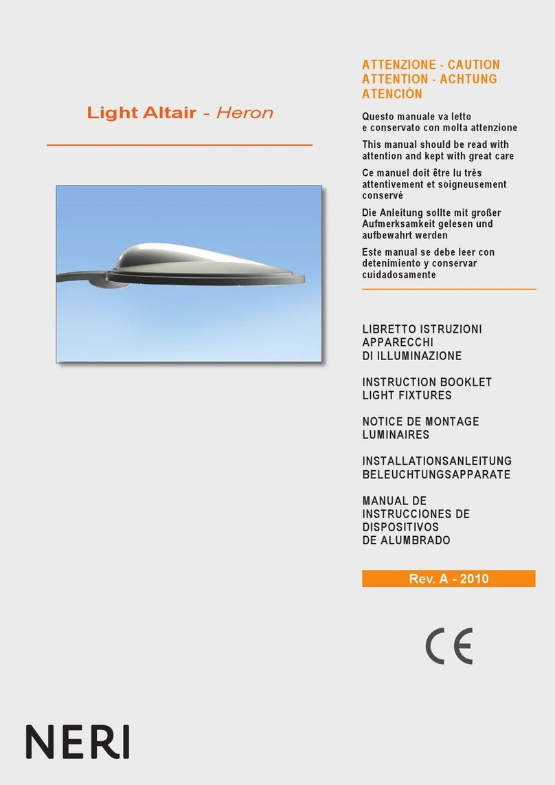
NERI Altair Heron User manual
NERI
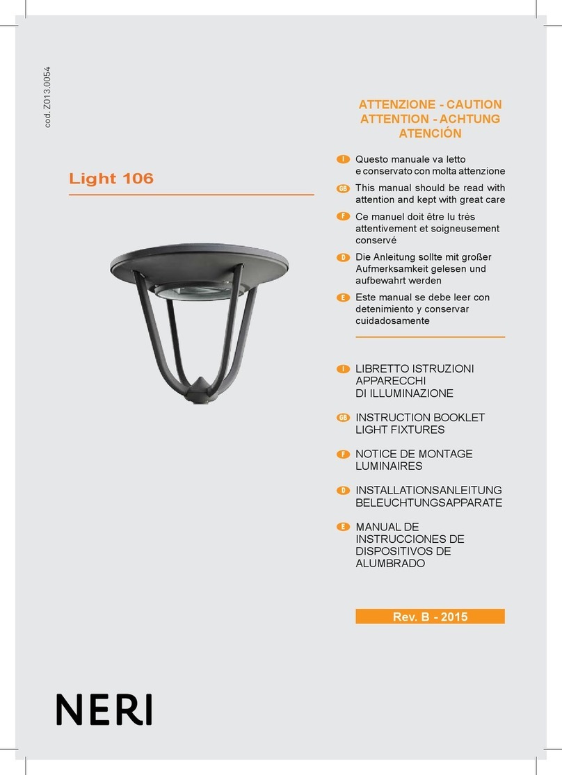
NERI Light 106 User manual
NERI
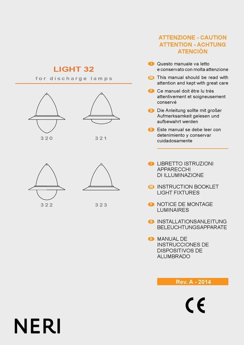
NERI LIGHT 32 Series User manual
NERI
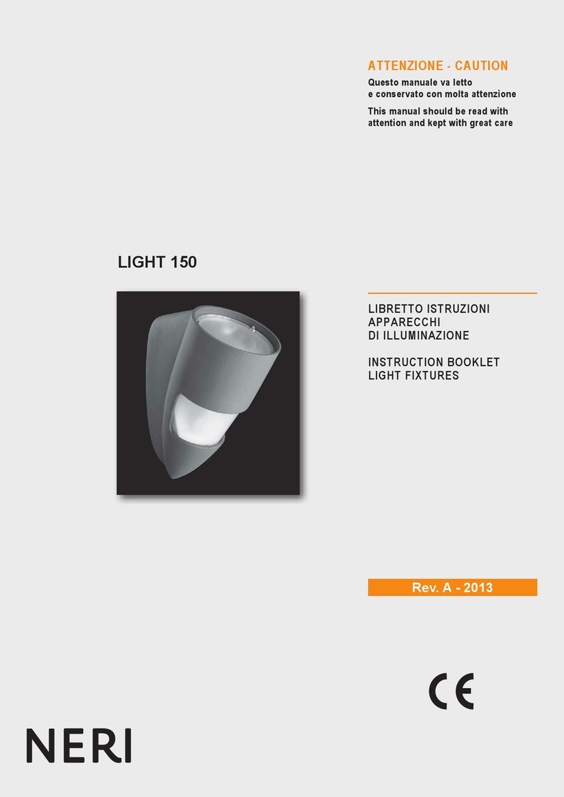
NERI LIGHT 150 User manual
NERI
NERI Nebula L User manual
NERI
NERI LIGHT 22 Series User manual

NERI
NERI LIGHT 500 User manual
NERI
NERI Light 23 Series User manual
NERI
NERI LIGHT 400 User manual
NERI
NERI LIGHT 804 User manual
Popular Light Fixture manuals by other brands
Lightolier
Lightolier ProSpec 26383W specification

Bebe Sounds
Bebe Sounds NL044 Easy to Use

Chauvet
Chauvet J-Five user manual
Cooper Lighting
Cooper Lighting Halo H1BSMLRG specification
Cooper Lighting
Cooper Lighting 12X-HZB Series installation instructions
Cooper Lighting
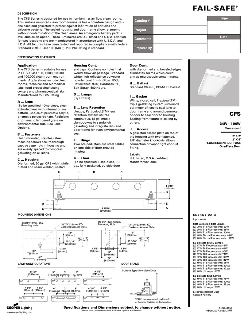
Cooper Lighting FAIL-SAFE CFS Specifications
