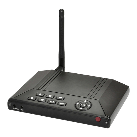
Ness PRO-LD User manual

PRO-LD
DIALLER ALARM SYSTEM
USER MANUAL
©2000 Ness Security Products Pty Ltd. All rights reserved.
PRO-LD User Manual V3.0
To the best of our knowledge, the information contained in this manual is correct at the time of
going to print. Ness Security Products reserves the right to make changes to the features and
specifications at any time and without notice in the course of product development.
WWW.NESS.COM.AU
Quality
Endorsed
Company
ISO9001
LIC.No. QEC2074
NSW Head Office only
Ness Security Products Pty Ltd ACN 069 984 372
N55
SYDNEY
028825 9222
MELBOURNE
039878 1022
ADELAIDE
088277 7255
NZ (NFS SECURITY)
649573 0401
HONG KONG
8522721 8097
BRISBANE
073343 7744
PERTH
089328 2511

CONTENTS
INTRODUCTION ...................................................................4
TERMINOLOGY ....................................................................4
CONTROLS AND INDICATIONS ..........................................6
KEYPAD ............................................................................6
BUTTONS .........................................................................6
AUDIBLE INDICATIONS ...................................................6
VISUAL INDICATIONS .....................................................7
OPERATION ..........................................................................8
OPERATINGRULES .........................................................8
AREA OPERATION...........................................................8
ARMING THE CONTROL PANEL .........................................9
DISARMING THE CONTROL PANEL.................................10
MONITOR MODE ................................................................ 11
EMERGENCY FUNCTIONS - PANIC .................................12
ALARMS ..............................................................................13
RESETTING AN ALARM.....................................................13
EXCLUDING ZONES ..........................................................14
INCLUDING ZONES............................................................15
ALARM MEMORY ...............................................................16
PROGRAMMING.................................................................17
TO ENTER PROGRAM MODE.......................................17
TO EXIT PROGRAM MODE...........................................17
HOW TO PROGRAM ACCESS CODES ............................18
HOWTOPROGRAMENTRYANDEXITTIMES......................19
TO PROGRAM ENTRY 1 TIMER (Option 26) ....................20
TO PROGRAM ENTRY 2 TIMER (Option 27) ....................20
TO PROGRAM EXIT TIMER (Option 28) ...........................20
PROGRAMMING SUMMARY .............................................21
TROUBLESHOOTING ........................................................22
INSTALLATION RECORD ...................................................23
OPERATION SUMMARY.....................................................24
PRO-L / PRO-LD User Manual 3


TERMINOLOGY
The microcomputer based 8 Zone
CONTROL PANEL forms the heart of
your security system and connects to all
other equipment. Each ZONE of the
Panel will be connected to one or more
detection devices to protect an area
such as the front door, hallway,
windows, etc.
The Panel is said to be ARMED when it
is set to detect an intruder. At other
times it is DISARMED.
Normally a zone is considered
SECURED. Activation of a detection
device will cause the zone to be
UNSECURED and may cause an alarm.
Detectors such as fire detectors and
panic buttons must be able to generate
an alarm at all times regardless of the
Panel setting. A zone with this
assignment is called a 24 HOUR ZONE.
Some detection devices may only be
required to generate an alarm or
warning only when the panel is
DISARMED. A zone with this
assignment is called a DAY ZONE.
Before leaving the premises you must
ARM the Panel to enable it to detect
intruders and generate an alarm. After
ARMING, the Panel will ignore
detectors for the EXIT DELAY TIME to
enable you to depart without triggering
an alarm.
When you enter the premises the Panel
will ignore selected zones for the
ENTRY DELAY TIME and will not alarm
unless you fail to DISARM the panel
during this allowed time.
PRO-L / PRO-LD User Manual 5
MONITOR MODE allows selected
zones to be armed while leaving others
disarmed if you wish to protect a
number of zones while you are at
home.
If you wish to split your alarm system
into two areas with access limited to
each area by code numbers then
AREA operation is used.
The Control Panel housing and the
metal covers over external sirens are
protected by TAMPER snitches to
detect someone attempting to disable
the security system. Activation of these
switches will cause an instant TAMPER
ALARM.
If a detector becomes faulty, you can
EXCLUDE the associated zone so that
it is totally ignored and cannot generate
an alarm. INCLUDING the zone will
enable it to generate an alarm again.
The Control Panel is fitted with a
rechargeable STAND-BY BATTERY to
ensure your security system continues
to operate if the MAINS POWER is
interrupted. This battery is checked
every hour and whenever you Arm the
Panel.
Whenever an alarm occurs, it may be
silenced by entering an ACCESS
CODE, otherwise it will reset at the end
of ALARM RESET TIME. All alarms
are stored in MEMORY and may be
viewed at any time by entering
MEMORY MODE.





HOW TO PROGRAM ENTRY & EXIT TIMES
Your PRO-L Control Panel will have
zone(s) which are called Entry/Exit
zones. These are the zone(s) which you
normally enter and leave your premises
by. To allow you to do so without
causing a false alarm, there is an Exit
Time which the Control Panel gives you
to depart your premises after you Arm
the Panel. There are 2 separate Entry
Times which the Control Panel gives
you to Disarm the Panel when you have
entered the premises before an alarm
occurs.
Your installer may have programmed
zones with a long entry time and a short
entry time zone. (A long and short entry
time is useful if you enter by a garage
or a front door).
To Program You Must Know a Few
Rules
Exit Time can be programmed from 1 to
99 seconds in 1 second increments.
PRO-L / PRO-LD User Manual 19
Entry 1 time can be programmed from
1 to 99 seconds in 1 second
increments.
Entn; 2 time can be programmed from
10 to 990 seconds in 10 second
increments
Each one of the timers has a 2 digit
program option number.
The current timer value is displayed by
the PRO-L when you select a timer
option. The value is displayed bv
flashing out the value on the numeric
zone lights 1 to 8, 9 = battery and 0 =
Mains at 1 second intervals.
When vou change the timer value the
new value is displayed as above. The
option numbers are as follows:
Entry 1 Timer = option 26
Entry 2 Timer = option 27
Exit Time = option 28
Programming always follows this
sequence;


PROGRAMMING SUMMARY
Your PRO-L Dialler may be
programmed to dial your home or a
friends home to report that an alarm has
occurred. The Dialler will call your
programmed telephone number and will
sound a series of fast beeps on the
telephone line.
When you hear the beeps press any of
the following digits on your phone; 2, 3,
4, 5, 6, 8, 9, 0 or # until the beeping
stops. If you do not respond to the
Dialler, it will hang up and repeat the
message up to 20 times!
PRO-L / PRO-LD User Manual 21
NOTE: Your phone may not be capable
of responding correctly in which case
your installer would have supplied you
with a hand-held generator instead.
NOTE: If you pick up the phone after
only 1 or 2 rings you may need to press
one of the above digits to start the
Dialler message or you can just wait
until the message starts by itself - this
could take up to 10 seconds.
OPTIONAL DIALLER-TO-HOME REPORTING
OPTION CODE DEFAULT PROGRAMMED
Acess Code 1 P11E Code E Code E
Acess Code 2 P12E Code E Code E
Acess Code 3 P13E Code E Code E
Acess Code 4 P14E Code E Code E
Acess Code 5 P15E Code E Code E
Acess Code 6 P16E Code E Code E
Acess Code 7 P17E Code E Code E
Acess Code 8 P18E Code E Code E
Acess Code 9 P19E Code E Code E
Acess Code 10 P20E Code E Code E
Acess Code 11 P21E Code E Code E
Acess Code 12 P22E Code E Code E
Acess Code 13 P23E Code E Code E
Acess Code 14 P24E Code E Code E
Acess Code 15 P25E Code E Code E
Entry Time 1 P26E Time E 20 seconds
Entry Time 2 P27E Time E 60 seconds
Exit Time P28E Time E 60 seconds
Table of contents
Other Ness Security System manuals

Ness
Ness Guardpost User manual

Ness
Ness Lux Quick start guide

Ness
Ness 5000 Series User manual

Ness
Ness Guardpost Assembly instructions

Ness
Ness MEDI-ALARM Owner's manual

Ness
Ness 5000 Series User manual

Ness
Ness LUX Quick start guide

Ness
Ness Radio Siren Quick start guide

Ness
Ness Guardpost User manual

Ness
Ness SmartLiving 505 Assembly instructions