netvox R718DA2 User manual

Wireless 2-Gang Vibration Sensor Rolling Ball Type
R718DA2
Wireless 2-Gang Vibration Sensor,
Rolling Ball Type
R718DA2
User Manual
Copyright©Netvox Technology Co., Ltd.
This document contains proprietary technical information which is the property of NETVOX Technology. It shall
be maintained in strict confidence and shall not be disclosed to other parties, in whole or in part, without written
permission of NETVOX Technology. The specifications are subject to change without prior notice.

1
Table of Content
1. Introduction......................................................................................................................................2
2. Appearance.......................................................................................................................................3
3. Main Features...................................................................................................................................3
4. Set up Instruction..............................................................................................................................4
5. Data Report ......................................................................................................................................5
5.1 Example of ReportDataCmd......................................................................................................5
5.2 Example of ConfigureCmd........................................................................................................6
5.3 Example for MinTime/MaxTime logic ......................................................................................7
6. Installation........................................................................................................................................9
7. Information about Battery Passivation .............................................................................................9
7.1 To determine whether a battery requires activation....................................................................9
7.2 How to activate the battery ........................................................................................................9
8. Important Maintenance Instruction.................................................................................................10

2
1. Introduction
R718DA2 is a ball-type two-way vibration sensors of Netvox ClassA type equipment based on LoRaWAN open protocol. The
sensor is attached to the detected device with magnet. When the device vibrates, the sensor is triggered. R718DA2
immediately sends the trigger information to the gateway. R718DA2 is compatible with LoRaWAN protocol.
LoRa Wireless Technology:
LoRa is a wireless communication technology dedicated to long distance and low power consumption. Compared with other
communication methods, LoRa spread spectrum modulation method greatly increases to expand the communication distance.
Widely used in long-distance, low-data wireless communications. For example, automatic meter reading, building automation
equipment, wireless security systems, industrial monitoring. Main features include small size, low power consumption,
transmission distance, anti-interference ability and so on.
LoRaWAN:
LoRaWAN uses LoRa technology to define end-to-end standard specifications to ensure interoperability between devices and
gateways from different manufacturers.
3
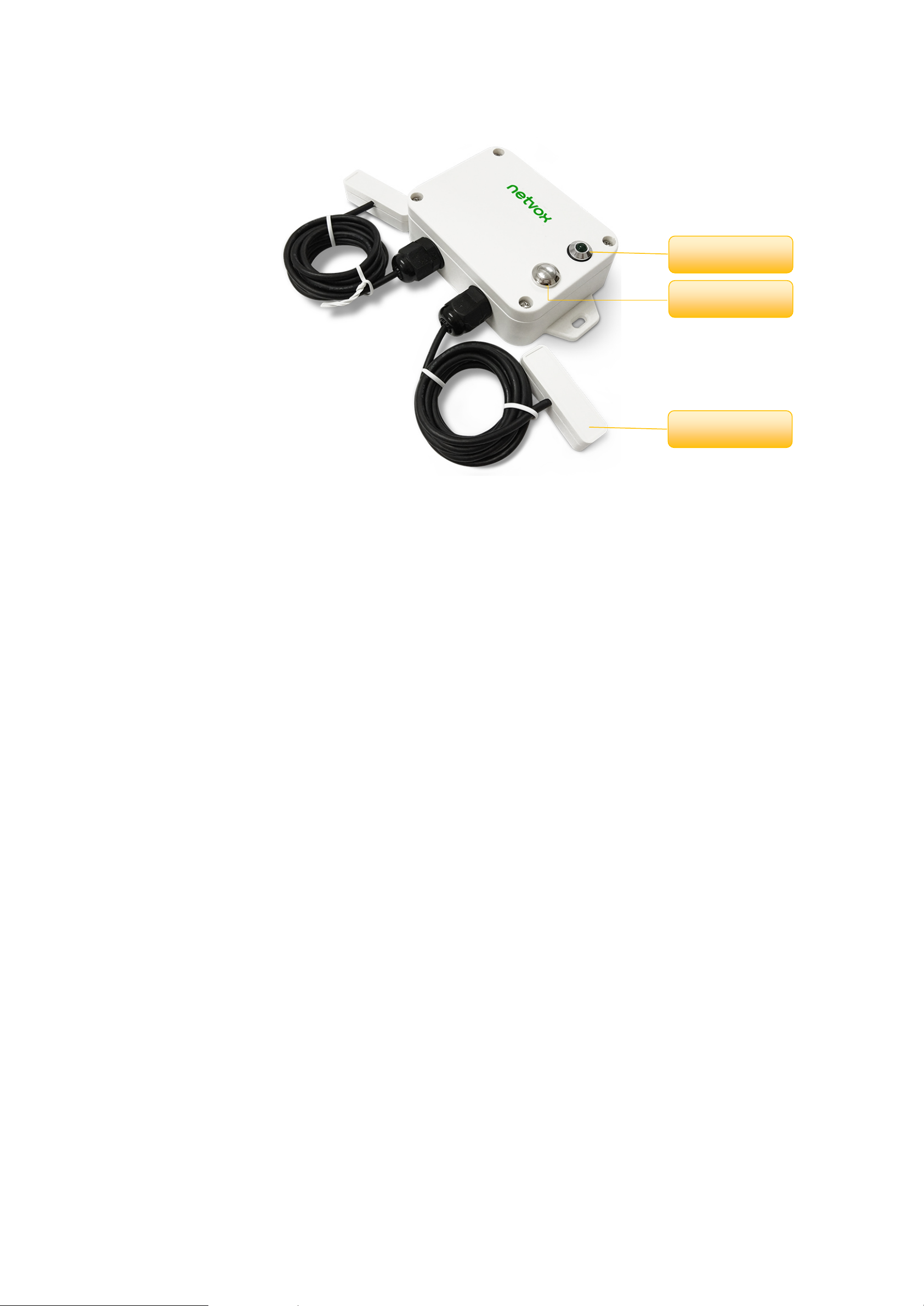
2. Appearance
3. Main Features
Adopt SX1276 wireless communication module
2 x 3.6V ER14505 AA size lithium batteries
Trigger the vibration sensor, the device will send trigger information
The base is equipped with a magnet that can be attached to the magnetic substance
IP Ratings: Main part- IP65/IP67 (Optional), Sensor-/IP67
Compatible with LoRaWAN TM Class A
Frequency hopping spread spectrum technology
Configuration parameters can be configured through third-party software platforms
Applicable to third-party platforms: Actility / ThingPark, TTN, MyDevices / Cayenne
Low power consumption and long battery life
Note:
Battery life is determined by the sensor reporting frequency and other variables . Please refer to
http://www.netvox.com.tw/electric/electric_calc.html
On this website, users can find various types of battery life time in different configurations.
Indicator
Function Key
Vibration Sensor

4
4. Set up Instruction
On/Off
Power on Insert batteries (Users may need a screwdriver to open)
Turn on Press and hold the function key for 3 seconds and the green indicator flash once.
Turn off (Restore to factory setting) Press and hold the function key for 5 seconds and the green indicator flashes 20 times.
Power off Remove Batteries.
Note:
1. Remove and insert the battery; the device is at off state by default.
2. On/off interval is suggested to be about 10 seconds to avoid the interference of
capacitor inductance and other energy storage components.
3. For the first 5 second after powering on, the device will be in engineering test mode.
Network Joining
Never joined the network
Turn on the device to search the network to join.
The green indicator stays on for 5 seconds: success
The green indicator remains off: fail
Had joined the network
Turn on the device to search the previous network to join.
The green indicator stays on for 5 seconds: success
The green indicator remains off: fail
Fail to join the network
(when the device is on)
Suggest to check the device verification information on the gateway or consult your
platform server provider.
Function Key
Press and hold for 5 seconds
Restore to factory setting / Turn off
The green indicator flashes 20 times: success
The green indicator remains off: fail
Press once The device is in the network: the green indicator flashes once and sends a report
The device is not in the network: the green indicator remains off
Sleeping Mode
The device is on and in the network
Sleeping period: Min Interval.
When the reportchange exceeds setting value or the state changes: send a data report
according to Min Interval.
Low Voltage Warning
Low Voltage
3.2V

5
5. Data Report
Data report configuration and sending period are as following:
5.1 Example of ReportDataCmd
FPort:0x06
Bytes 1 1 1 Var (Fix=8 Bytes)
Version DeviceType ReportType NetvoxPayLoadData
Version– 1 byte –0x01——the Version of NetvoxLoRaWAN Application Command Version
DeviceType– 1 byte – Device Type of Device
The devicetype is listed in Netvox LoRaWAN Application Devicetype doc
ReportType – 1 byte –the presentation of the NetvoxPayLoadData,according the devicetype
NetvoxPayLoadData– Fixed bytes (Fixed =8bytes)
Min Interval
(Unit:second)
Max Interval
(Unit:second) Reportable Change Current Change≥
Reportable Change
Current Change<
Reportable Change
Any number between
1~65535
Any number between
1~65535 Can not be 0 Report
per Min Interval
Report
per Max Interval
The device will immediately send a version packet report and the vibration report data
The device sends data in the default configuration before any configuration is done.
Default setting:
Max Interval: 0x0E10 (3600s)
Min Interval: 0x0E10 (3600s)
BatteryVoltageChange: 0x01 (0.1V)
R718DA2 Trigger:
When the device senses vibration and the ball is shaken, an alarm message will be reported.
The shaking alarm bit is “1”.
The static and non-shaking alarm bit is “0”.
Note:
The device report interval will be programmed based on the default firmware which may vary.
The interval between two reports must be the minimum time.
Please refer Netvox LoRaWANApplication Command document and Netvox Lora Command Resolver
http://cmddoc.netvoxcloud.com/cmddoc to resolve uplink data.

6
Device Device
Type
Report
Type NetvoxPayLoadData
R718DA2 0x2F
0x00
SoftwareVersion
(1Byte)
Eg.0x0A—V1.0
Hardware
Version
(1Byte)
DateCode
(4Bytes,
eg 0x20170503)
Reserved
(2Bytes,fixed 0x00)
0x01 Battery
(1Byte, unit:0.1V)
Status 1
(1Byte 0:off 1:on)
Status 2
(1Byte 0:off 1:on)
Reserved
(5Bytes,fixed 0x00)
Example 1 of Uplink: 012F012401000000000000
1st byte (01): Version
2nd byte (2F): DeviceType 0x2F -R718DA2
3rd byte (01): ReportType
4th byte (24): Battery -3.6V, 24(Hex) = 36(Dec), 36x0.1v=3.6v
5th byte (01): Status -on
6th byte (00): Status -off
7th -11th byte (0000000000): Reserved
Example 2 of Uplink: 012F01A000010000000000
1st byte (01): Version
2nd byte (2F): DeviceType 0x2F -R718DA2
3rd byte (01): ReportType
4th byte (A0): Battery -3.2V, 20(HEX)=32(DEC),32*0.1v=3.2v // Low battery
5th byte (00): Status -off
6th byte (01): Status -on
7th -11th byte (0000000000): Reserved
5.2 Example of ConfigureCmd
FPort:0x07
Bytes 1 1 Var (Fix =9 Bytes)
CmdID DeviceType NetvoxPayLoadData
CmdID– 1 byte
DeviceType– 1 byte – Device Type of Device
NetvoxPayLoadData– var bytes (Max=9bytes)

7
(1)Configure device parameters
MinTime = 1 min, MaxTime = 1 min, BatteryChange = 0.1v
Downlink: 012F003C003C0100000000 003C(Hex) = 60(Dec)
Response:
812F000000000000000000 (Configuration success)
812F010000000000000000 (Configuration failure)
(2)Read device configuration parameters
Downlink: 022F000000000000000000
Response:
822F003C003C0100000000 (Current configuration)
5.3 Example for MinTime/MaxTime logic
Example#1 based on MinTime = 1 Hour, MaxTime= 1 Hour, Reportable Change i.e. BatteryVoltageChange=0.1V
MaxTime MaxTime
Sleeping(MinTime) Sleeping(MinTime)
Note: MaxTime=MinTime. Data will only be report according to MaxTime (MinTime) duration regardless BatteryVoltageChange
value.
Description Device CmdID
Device
Type NetvoxPayLoadData
Config
ReportReq
R718DA2
0x01
0x2F
MinTime
(2bytes Unit: s)
MaxTime
(2bytes Unit: s)
BatteryChange
(1byte Unit: 0.1v)
Reserved
(4Bytes, Fixed 0x00)
Config
ReportRsp 0x81 Status
(0x00_success)
Reserved
(8Bytes, Fixed 0x00)
ReadConfig
ReportReq 0x02 Reserved
(9Bytes, Fixed 0x00)
ReadConfig
ReportRsp 0x82 MinTime
(2bytes Unit: s)
MaxTime
(2bytes Unit: s)
BatteryChange
(1byte Unit: 0.1v)
Reserved
(4Bytes, Fixed 0x00)
Wake up and collects data
REPORTS 3.6V
Wakes up and collects data
REPORTS 3.6V
Wakes up and collects data
REPORTS 3.6V
8
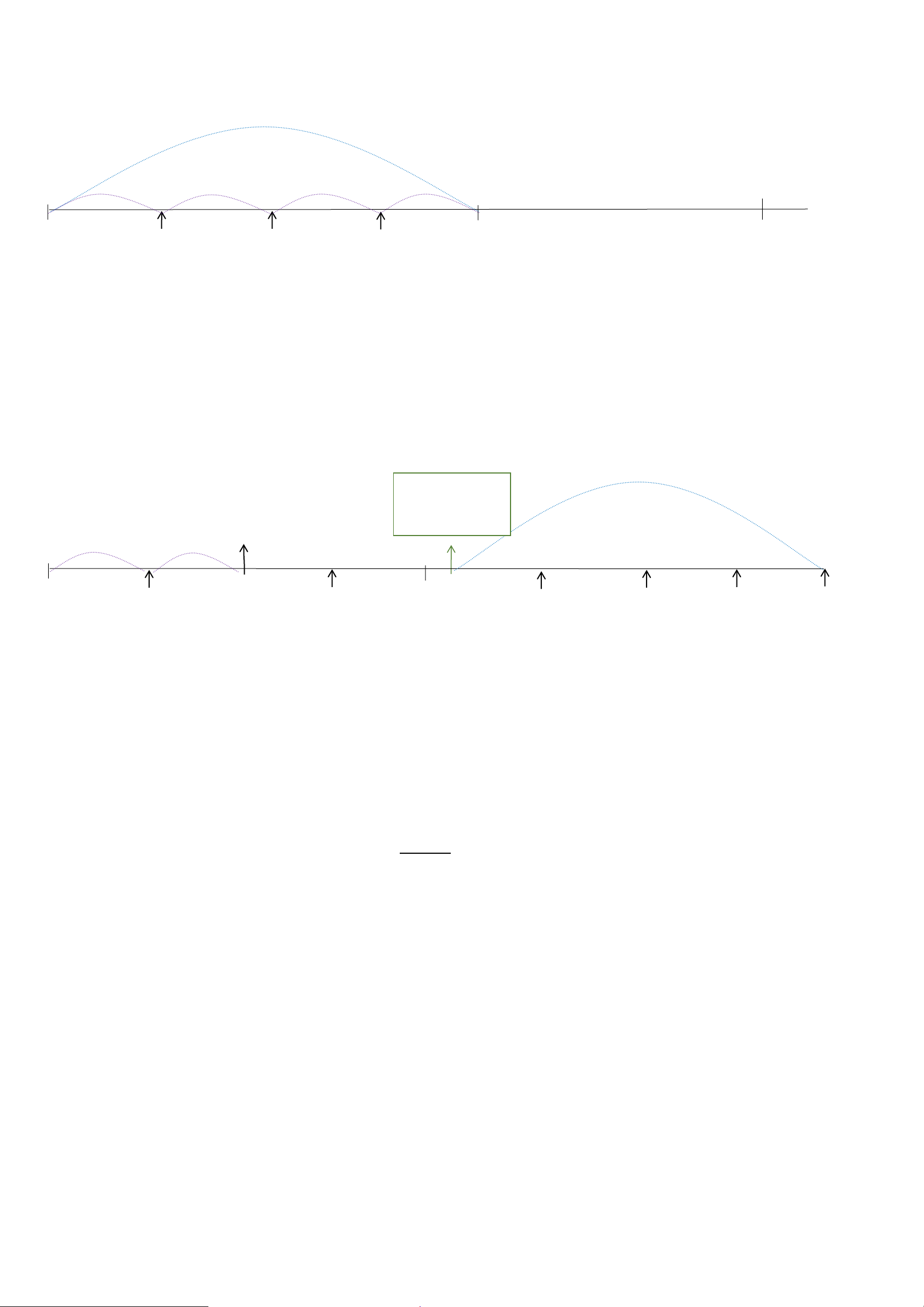
Example#2 based on MinTime = 15 Minutes, MaxTime= 1 Hour, Reportable Change i.e. BatteryVoltageChange= 0.1V.
MaxTime
Sleeping(MinTime) sleeping sleeping sleeping
0H 15th M 30th M 45th M 1H 2H
Example#3 based on MinTime = 15 Minutes, MaxTime= 1 Hour, Reportable Change i.e. BatteryVoltageChange= 0.1V.
MaxTime
sleeping sleeping ...
0H 15th M 30th M 45th M 1H 1H 10th M 1H 25th M 1H 40th M 1H 55th M 2H 10th M
Notes :
1) The device only wakes up and performs data sampling according to MinTime Interval. When it is sleeping, it does not
collect data.
2) The data collected is compared with the last data reported. If the data variation is greater than the ReportableChange value,
the device reports according to MinTime interval. If the data variation is not greater than the last data reported, the device
reports according to MaxTime interval.
3) We do not recommend to set the MinTime Interval value too low. If the MinTime Interval is too low, the device wakes up
frequently and the battery will be drained soon.
4) Whenever the device sends a report, no matter resulting from data variation, button pushed or MaxTime interval, another
cycle of MinTime/MaxTime calculation is started.
Wakes up and
collects data
3.6V
Does not report
Wakes up and
collects data
3.6V
Does not report
Wakes up and
collects data
3.6V
Does not report
Wakes up and
collects data
REPORTS 3.6V
Wakes up and
collects data
REPORT 3.6V
Wakes up and
collects data
REPORTS 3.6V
Wakes up and collects data
3.5V |3.5-3.6|=0.1
REPORTS 3.5V
Wakes up and
collects data
3.5V
Does not report
Wakes up and
collects data
3.5V
Does not report
Wakes up and
collects data
3.5V
Does not report
Wakes up and
collects data 3.5V
Does not report
Wakes up and
collects data
3.5V
Does not report
Wakes up and
collects data
REPORTS 3.5V
Wakes up and
collects data
3.6V
Does not report
Users push the button,
REPORTS 3.5V.
Recalculate MaxTime.

9
6. Installation
When installing the vibration sensor, pay attention to the fact that the direction of the vibration and the long side of the sensor on
the same as below figure.
7. Information about Battery Passivation
Many of Netvox devices are powered by 3.6V ER14505 Li-SOCl2 (lithium-thionyl chloride) batteries that offer many
advantages including low self-discharge rate and high energy density.
However, primary lithium batteries like Li-SOCl2 batteries will form a passivation layer as a reaction between the lithium
anode and thionyl chloride if they are in storage for a long time or if the storage temperature is too high. This lithium chloride
layer prevents rapid self-discharge caused by continuous reaction between lithium and thionyl chloride, but battery passivation
may also lead to voltage delay when the batteries are put into operation, and our devices may not work correctly in this situation.
As a result, please make sure to source batteries from reliable vendors, and it is suggested that if the storage period is more
than one month from the date of battery production, all the batteries should be activated.
If encountering the situation of battery passivation, users can activate the battery to eliminate the battery hysteresis.
ER14505 Battery Passivation:
7.1 To determine whether a battery requires activation
Connect a new ER14505 battery to a resistor in parallel, and check the voltage of the circuit.
If the voltage is below 3.3V, it means the battery requires activation.
7.2 How to activate the battery
a. Connect a battery to a resistor in parallel
b. Keep the connection for 5~8 minutes

10
c. The voltage of the circuit should be ≧3.3, indicating successful activation.
Brand Load Resistance Activation Time Activation Current
NHTONE 165 Ω 5 minutes 20mA
RAMWAY 67 Ω 8 minutes 50mA
EVE 67 Ω 8 minutes 50mA
SAFT 67 Ω 8 minutes 50mA
Note:
If you buy batteries from other than the above four manufacturers, then the battery activation time, activation current, and
required load resistance shall be mainly subject to the announcement of each manufacturer.
8. Important Maintenance Instruction
Your device is a product of superior design and craftsmanship and should be used with care. The following suggestions will help
you use the warranty service effectively.
•Keep the equipment dry. Rain, moisture,and variousliquids ormoisture may containminerals that can corrodeelectroniccircuits.
In case the device is wet, please dry it completely.
•Do not use or store in dusty or dirty areas. This can damage its detachable parts and electronic components.
•Do not store in excessive heat. High temperatures can shorten the life of electronic devices, destroy batteries, and deform or melt
some plastic parts.
•Do not store in a cold place. Otherwise, when the temperature rises to normal temperature, moisture will form inside, which will
destroy the board.
•Do not throw,knock orshake the device.Rough handling of equipment can destroy internal circuit boards and delicate structures.
•Do not wash with strong chemicals, detergents or strong detergents.
•Do not apply with paint. Smudges can block debris in detachable parts and affect normal operation.
•Do not throw the battery into a fire to prevent the battery from exploding. Damaged batteries may also explode.
All of the above suggestions apply equally to your device, battery and accessories.
If any device is not working properly, please take it to the nearest authorized service facility for repair.
Table of contents
Other netvox Accessories manuals

netvox
netvox R718DA User manual

netvox
netvox R718PA22 User manual

netvox
netvox Z809B User manual

netvox
netvox R313WA User manual

netvox
netvox R711 User manual

netvox
netvox RA0723 User manual

netvox
netvox R313G User manual

netvox
netvox R718G User manual

netvox
netvox R718PA11 User manual

netvox
netvox R718VA User manual

netvox
netvox R718A User manual

netvox
netvox R718VA User manual

netvox
netvox RA0716 User manual

netvox
netvox R718PQA User manual

netvox
netvox RA0716A User manual

netvox
netvox R718CXAB User manual

netvox
netvox ZB11C1 User manual

netvox
netvox R718IJK User manual

netvox
netvox R712 User manual

netvox
netvox R311CA User manual


