P.O. Box 1306, Newport Beach, California 92663 • Phone: 714-751-0488 • Fax: 714-957-1621 • E-Mail: techservice@newmarpower.com
www.newmarpower.com
9
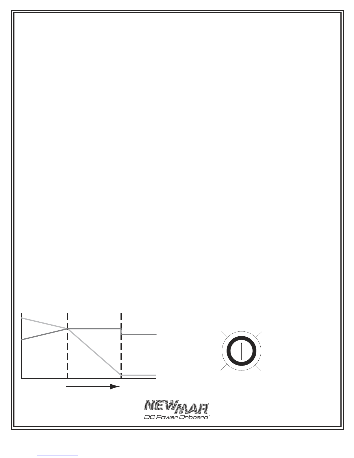
C) Gel-Cell/Lead Acid Selector Switch
According to most battery manufacturers, the ideal charging
regimen for gel-cell and wet or flooded lead acid batteries differs
somewhat.
The gelled electrolyte in a sealed battery may be lost or damaged
by high voltage and, once lost, cannot be replaced as it can
with a wet lead acid battery. Manufacturers of gel-cells usually
recommend an ideal charge voltage which is slightly lower for a
gel-cell than a lead acid battery.
However, when the charger is in the float voltage mode over
lengthier periods of time, gelled electrolyte in a sealed battery
is not susceptible to evaporation, as is the non-immobilized
electrolyte of a wet lead acid battery. This evaporation can be
accelerated by the applied voltage. Consequently, the ideal float
voltage is slightly higher for a gel-cell than a lead acid battery.
The ideal charge/float regimen has been programmed into the
Phase Three Charger for either sealed gel-cell or flooded lead acid
batteries. Simply make the proper selection for your battery type
via the slide switch on the right side of the charger. The switch
positions are indicated on the front panel (up for Gel-Cell batteries,
and down for Lead-Acid/AGM type batteries). Use a ball point
pen or similar object to slide it into the correct position. The charger
is shipped from the factory set for Lead-Acid/AGM batteries.
Note: A wide variety of batteries are available which do not
conform to conventional descriptions as “gel-cell” or “lead-acid”.
You are advised to consult the manufacturer of your particular
battery as to proper charging regimen, and use the battery
type selection switch setting which most closely conforms to the
recommended voltages.
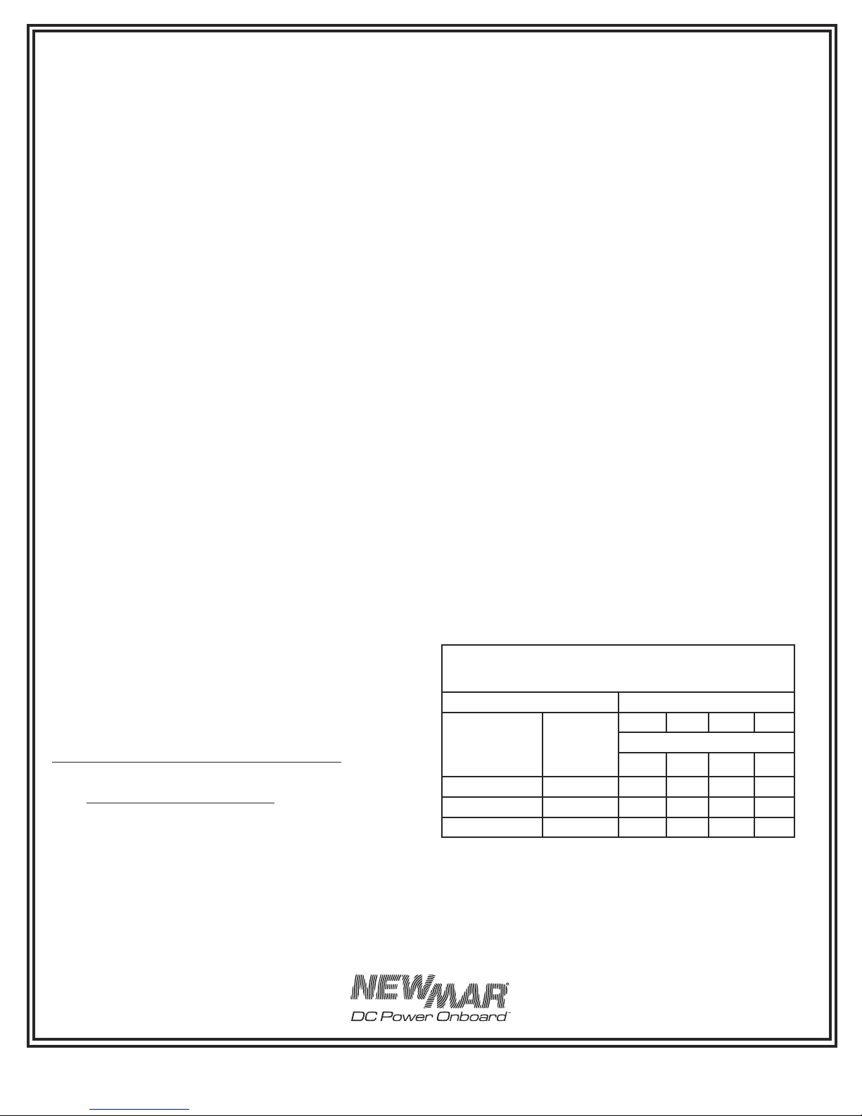
See the SPECIFICATIONS section for the actual preset charge and
float voltages for each battery type/charger model.
D) Remote Monitor Panel Option
A Remote Monitor Panel is available from NEWMAR (model RP)
which will enable you to monitor the charger’s status at-a-glance
from a remote location. Red and green L.E.D.’s indicate whether
the charger is in the bulk, absorption or float phase of the charge
cycle. In addition, the panel features a re-initialize button, which,
when pressed, will cause the charger to restart the three phase
cycle. This resets the time-out circuit (see section B, Time-Out
Circuit, above). Note: The charger may not stay in the bulk or
absorption mode after pressing the re-initialize button. If batteries
are at or near full charge, the charger will quickly revert to the
float mode.
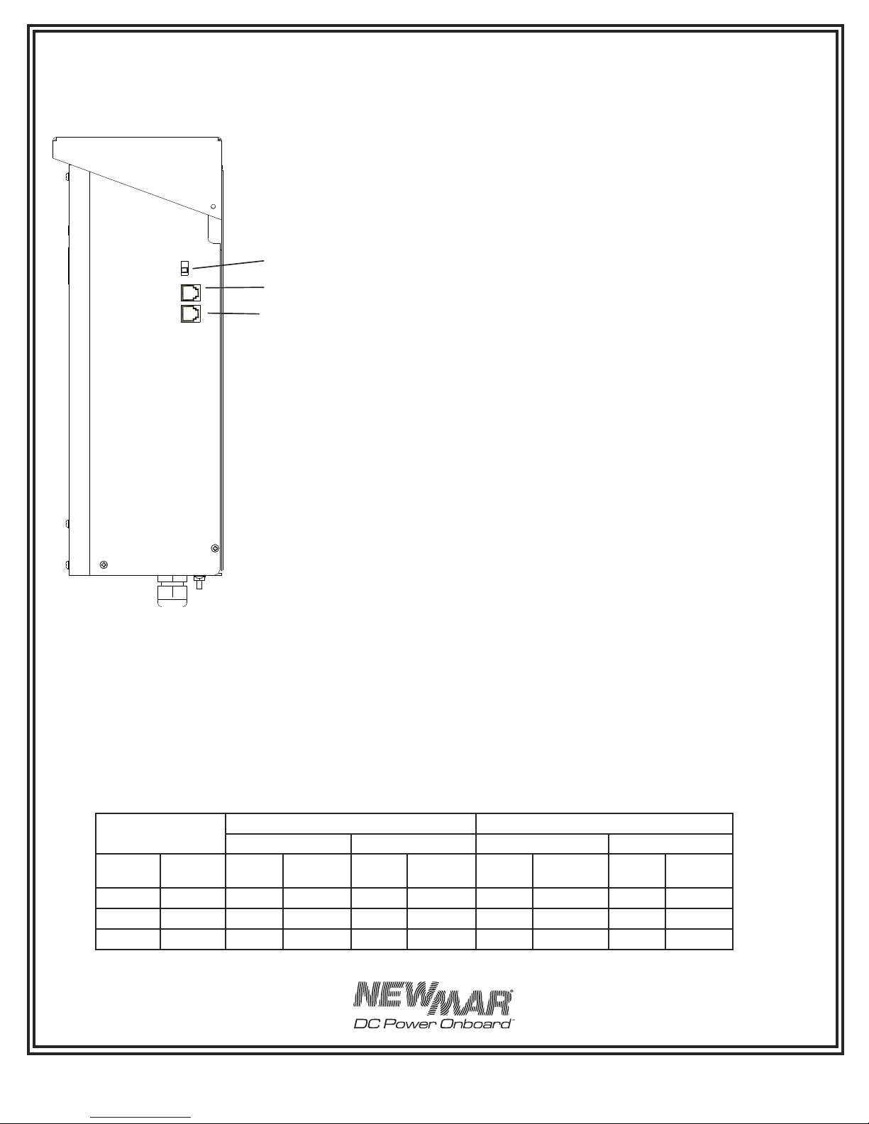
The panel comes pre-wired with 30’ of cable and 4 mounting
screws. Simply install the panel at the desired location and insert
the plug on the end of the cable into the remote panel jack
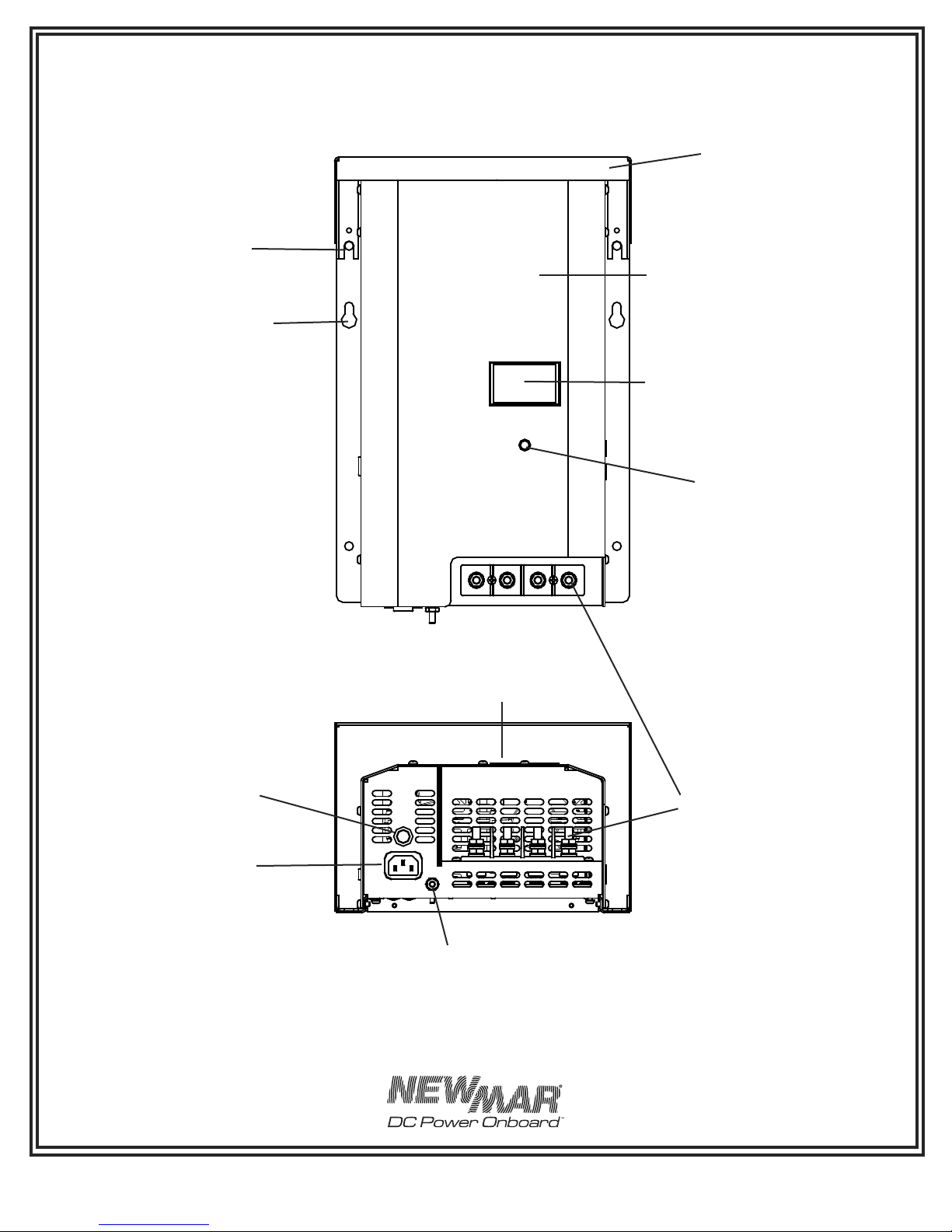
which is located on the right side of the charger. (See FIGURE
5) The remote panel jack is identified on the front panel. Note:
Inadvertently putting the remote panel plug into the temp
compensation jack (or vice versa) will not harm the charger.
If additional cable length is required, additional cable is
commonly available from most electronics supply retailers such as
Radio Shack/Tandy. Request a 6 conductor modular-to-modular
line cord (part number 279-422, 25 feet long) and a 6 pin modular
in-line non-reversing coupler (part number 279-423).
E) Temperature Compensation Option
Because low battery temperature increases resistance to charging
and high battery temperature reduces impedance, requiring
a lower charge voltage, the ideal charging voltage will vary
depending on the temperature of the battery’s environment when
it is being charged.
If a charger has a fixed output voltage which is ideal at, say 72_
F that same output may cause a battery charged in consistently
high temperature environment to be overcharged, resulting
in excessive loss of electrolyte. Conversely, if the batteries are
in a consistently cool environment, they may be chronically
undercharged, resulting in sulfation of the battery plates. Either of
these two conditions will shorten battery life.
Therefore, the Phase Three Charger is designed to utilize an
optional remote sensor (available from NEWMAR, model TCS-
12/40) which provides automatic temperature compensation. The
remote sensor will signal the charger to fine tune its output voltage
so that it is properly matched to the temperature of the battery/
battery environment. The adjustment rate is approximately -3mV
per cell per _C. (Note: The temperature compensation option is
strongly recommended for sealed, valve-regulated or gel-cell
batteries.)
The remote sensor is provided with 30’ of cable (model TCS-12/24-
40 is provided with 40’ of cable). One end of the cable is plugged
into the temperature compensation jack which is located on the
right side of the charger. (See FIGURE 5.) The temp sensor jack is
identified on the front panel. If additional cable length is required,
additional cable is commonly available from most electronics
supply retailers as Radio Shack/Tandy. Request a 6 conductor
modular-to-modular line cord (part number 279-422, 25 feet long)
and 6 pin modular in-line non-reversing coupler (279-423).
The sensor itself should be mounted on the inside of the battery
box, or more ideally, mounted onto one of the batteries using a
clamp or a small amount of silicon-type adhesive. The sensor has
a hole in the center which will accommodate a #6 screw. If you
have access to the exterior of a wall of the battery box, you may
drill a hole in the wall of the box and run the screw through to
mount the sensor onto the interior wall. Use caution when drilling
so that you do not accidently puncture the case of any battery
inside the box.
Important note: When wiring multiple units in parallel (see section
III-E) and using the temperature compensation option, you must
use a separate sensor for each charger, and the sensors must be
mounted close together in the same battery box or on the same
battery for proper operation.
FIGURE 5: Gell-Cell/Lead Acid Selector