NewMar PT-14W User manual

PhaseThree
ThreeStageSmartCharger
Installation/Operationmanual
Models:PT‐14W,PT‐25W,PT‐24‐8W,&PT‐24‐13W
CONTENTS
SectionTopicPage
I) GENERALINFORMATION.................................3
II) IMPORTANTSAFETYINFORMATION................4
III) INSTALLATION.................................................6
A)MaterialsProvided..........................6
B)Location..........................................6
C)Mounting........................................6
D)DCOutputWiring............................7
E)MultipleUnitParallelWiring...........9
F)ACInputWiring...............................9
IV) OPERATION.....................................................10
A)ThreeStageChargeRegimen...........10
B)Time‐OutCircuit..............................12
C)Gel‐Cell/Lead‐AcidSelectorSwitch..13
D)RemoteMonitorPanelOption........13
E)TemperatureCompensationOption.14
F)EqualizeTimerOption......................15
G)OutputAmmeter………………….……….16
H)Power‐OnIndicator………………….…..16
V) APPLICATIONNOTES........................................16
A)Start‐Up..........................................16
B)ConstantVersusOccasionalUse......16
C)ProperLoadSizing...........................17
D)OperationwithEngine....................17
E)OperationasaDCPowerSupply......17
VI) SPECIFICATIONS...............................................17
VII) TROUBLESHOOTING........................................18
VIII) BATTERYCARETIPS.........................................20
IX) REFERENCEAPPENDIX.....................................22
lUnitDimensionDrawing.……………..……………....23
M‐PT‐W4
AsofDecember08

QuickReferenceDrawing

I)GENERALINFORMATION
YourPhaseThreeSeriesBatteryChargerrepresentsanewphaseinchargerdesignandperformance,
employing"smart"switchingcircuitrywhichputsbatteriesthroughtheoptimumthree‐stepcharge
process,adaptsforgel‐cellorlead‐acidbatteries,featuresprecisevoltagecompensationforvarying
batterytemperature,isratedforcontinuousdutyandishousedinarugged,powdercoatedstainless
steelandaluminumcase.
Followingisabrieflistingofsomeofthemoreimportantfeatures/optionsofyourPhaseThreeCharger.
Eachisfullydetailedlaterinthismanual:
*Threestep“smart”charging:bulk,absorption,float
*Gelcell/lead‐acidswitchselectsoptimumcharge/floatvoltagesbasedonbatterytype
*Multipleoutputbankschargeindependentlybasedondemand
*"Universal"115/230VAC,50‐60Hzinput—canbeusedanywhereintheworld
*Currentlimitingpreventsdamagefromoverload
*Coolingfanallowscontinuousoperationatfull‐ratedoutput
*Highchargevoltagetime‐outcircuitpreventsoverchargeduringcontinuoushighamperage
demands
*Optionaltemperaturecompensationsensor(modelTCS‐12/24)finetunesoutputvoltagebasedon
batterytemperature
*Optionalremotepanel(modelRP)allowsremotemonitoringofchargerphasestatusandmanualre‐
initializationofthreestagechargecycle
*Optionalequalizationcircuitconnection
*Useasapowersupplywithoutin‐linebattery;allowscontinueduseofDCpoweredelectronics
(whenACisavailable)intheeventthatbatteriesmustbetakenoff‐lineorremoved
*Ruggedstainlesssteelcasewithdripshield
*ModelsPT‐14WandPT‐24‐8WcarrytheCEmark
*AllmodelsignitionprotectedperUSCGCFR183.410
Inaddition,yourPhaseThreeChargercarriesafulltwoyearwarrantyagainstdefectsinmaterialsor
workmanshipfromdateofpurchase.Carefulattentiontotheseinstructionsshouldhelpyoutoenjoy
yearsoftrouble‐freeservice.

II)IMPORTANTSAFETYINSTRUCTIONS
1.SAVETHESEINSTRUCTIONS—Thismanualcontainsimportantsafetyandoperatinginstructionsfor
thePhaseThreeBatteryCharger.
2.Beforeusingthisbatterycharger,readallinstructionsandcautionarymarkingson(1)thebattery
charger(2)thebattery,and(3)anyproductpoweredbythebattery.
3.CAUTION—Toreducetheriskofinjury,chargeonly6cell(PT‐14WandPT‐25W)or12cell(PT‐24‐8W
andPT‐24‐13W)lead‐acidrechargeablebatteries(flooded,AGM,gelorsealed).Othertypesofbatteries
mayburst,causingpersonalinjuryanddamage.
4.Donotexposechargertorainorspray.
5.UseofanattachmentnotrecommendedorsoldbyNEWMARmayresultinariskoffire,electricshock
orinjurytopersons.
6.Toreducetheriskofdamagetotheelectricplugandcord(ifpluggedintoanACoutlet),pullbyplug
ratherthancordwhendisconnectingthecharger.
7.Makesurethecordislocatedsothatitwillnotbesteppedon,trippedover,orotherwisesubjected
todamageorstress.
8.Anextensioncordshouldnotbeused.Useofanimpropercordcouldresultinariskoffireand
electricshock.
9.Donotoperatethechargerwithadamagedcordorplug;replacethemimmediately.
10.Donotoperatethechargerifithasreceivedasharpblow,beendropped,orotherwisedamaged;
takeittoaqualifiedserviceman.
11.Donotdisassemblethecharger;takeittoaqualifiedservicemanwhenserviceorrepairisnecessary.
Incorrectreassemblymayresultinariskofelectricshockandfire.
12.Toreducetheriskofelectricshock,disconnectthechargerfromACsourcebeforeattemptingany
maintenanceorcleaning.
WARNING—RISKOFEXPLOSIVEGASES
1.WORKINGINTHEVICINITYOFALEAD‐ACIDBATTERYISDANGEROUS.BATTERIESGENERATE
EXPLOSIVEGASESDURINGNORMALBATTERYOPERATION.FORTHISREASON,ITISOFUTMOST
IMPORTANCETHATBEFOREINSTALLINGANDUSINGYOURCHARGER,YOUREADTHISMANUALAND
FOLLOWTHEINSTRUCTIONSEXACTLY.
2.Toreducetheriskofbatteryexplosion,followtheseinstructionsandthosepublishedbythebattery
manufacturerandbythemanufacturerofanyequipmentyouintendtouseinthevicinityofthebattery.
Reviewallcautionarymarkingsontheseproducts.

PERSONALPRECAUTIONS
1.Someoneshouldbewithinrangeofyourvoiceorcloseenoughtocometoyouraidwhenyouwork
nearalead‐acidbattery.
2.Haveplentyoffreshwaterandsoapnearbyincasebatteryacidcontactsskin,clothingoreyes.
3.Wearcompleteeyeprotectionandclothingprotection.Avoidtouchingyoureyeswhileworkingnear
abattery.
4.Ifbatteryacidcontactsskinorclothing,washimmediatelywithsoapandwater.Ifbatteryacidenters
theeye,immediatelyfloodtheeyewithrunningcoldwaterforatleast10minutesandgetmedical
attentionimmediately.
5.NEVERsmokeorallowasparkorflameinthevicinityofthebatteryorengine.
6.Beextracautioustoreducetheriskofdroppingametaltoolontothebattery.Itmightsparkorshort‐
circuitthebatteryorotherelectricalpartandcauseanexplosion.
7.Removepersonalmetalitemssuchasrings,bracelets,necklacesandwatcheswhenworkingwitha
lead‐acidbattery.Alead‐acidbatterycanproduceashort‐circuitcurrenthighenoughtoweldaringor
theliketometal,causingasevereburn.
8.Usethebatterychargerforcharginggel‐cell,AGMorfloodedlead‐acidbatteriesonly.Itisnot
intendedtosupplypowertoalowvoltageelectricalsystemotherthaninastarter‐motorapplication.
Donotusethechargerforchargingdry‐cellbatteriesthatarecommonlyusedwithhomeappliances.
Thesebatteriesmayburstandcauseinjurytopersonsanddamagetoproperty.
9.NEVERchargeafrozenbattery.
PREPARINGTOCHARGE
1.Besuretheareaaroundthebatteryiswellventilated.
2.Cleanbatteryterminals.Becarefultokeepcorrosionfromcomingincontactwitheyes.
3.Adddistilledwaterineachcelluntilbatteryacidreacheslevelspecifiedbybatterymanufacturer.This
helpspurgeexcessivegasfromcells.Donotoverfill.Forasealedbatterywithoutcellcaps,carefully
followmanufacturer’srecharginginstructions.
4.Studyallbatterymanufacturers’specificprecautionssuchasremovingornotremovingcellcapswhile
chargingandrecommendedratesofcharge.
GROUNDINGANDACPOWERCORDCONNECTION
1.Thechargershouldbegroundedtoreducetheriskofelectricshock.
(Formarineapplicationsonly)EXTERNALCONNECTIONSTOTHECHARGERSHALLCOMPLYWITHUL
RECOMMENDATIONSAND/ORUNITEDSTATESCOASTGUARDELECTRICALREGULATIONS(33CFR183,
SUB‐PARTI)
(Formarineapplicationsonly)THEINSTALLATIONANDPROTECTIONOFVESSELWIRINGASSOCIATED
WITHBATTERYCHARGERSSHALLCOMPLYWITHABYCSTANDARDS;E‐8)ACELECTRICALSYSTEMSON
BOATS,E‐9)DCELECTRICALSYSTEMSONBOATS,ANDA‐20)BATTERYCHARGINGDEVICES.

III)INSTALLATION
A)MaterialsProvided
ThePhaseThreechargerisprovidedcompletelyassembledandreadyforinstallation.Theinstallermust
providefoursuitable1/4"mountingscrews/washers,aswellasDCoutputwiringandconnectors.
PropersizesandgaugesforthewireandconnectorsarenotedinsectionDfollowing.
B)Location
Thechargershouldbemountedonawall,bulkheadorothersuitablemountingsurfaceasclosetothe
batteriestobechargedaspossible.Donotmountthechargerdirectlyoverthebatteriesasbattery
fumesmaycauseexcessivecorrosion.Thechargerisignitionprotectedsoitisacceptabletolocatethe
unitinanareawhereignitionprotectedequipmentisrequired.Theareashouldbewellventilatedand
freefromexcessivemoisture,exhaustmanifoldsandbatteryfumes.
Verticalmountingispreferred.However,horizontalmountingisacceptablewhereabsolutelynecessary.
Donotmountthechargerwherewater,sprayorcondensationcanoccur,asthiswillshortenchargerlife.
Itshouldnotbelocatedwherethereisapossibilityofdustordebrisbeingdrawnintotheunitthrough
thefan.Aminimumof2"clearancearoundthechargerisrecommendedforpropercooling.
Ifthechargerislocatedinanextremeheatarea,suchasanunventilatedengineroom,andmaximum
operatingtemperatureisexceeded,anautomaticthermalprotectioncircuitwillshutthechargeroff.
Althoughitwillreturntoserviceautomaticallyaftercoolingsufficiently,thermalcyclingwillshortenthe
lifeofthecharger.Ifthisconditionoccursrepeatedly,thechargershouldberelocated.Foroptimum
performanceandlongerlifethechargershouldnotbelocatedinanareaofextremehightemperature.
C)Mounting
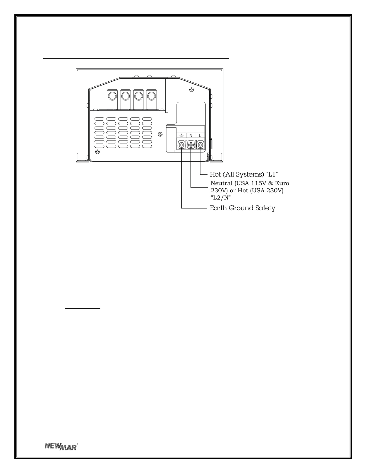
ImportantPre‐InstallationNote:ThewiringaccessportforACinputislocatedonthebottomofthe
charger.Ifthefactory‐installedACcordmustbechangedforanyreason,thisshouldbedonebefore
mounting,asaccesswillbedifficultafterwards.
Thechargermaybemountedoneitherametalornon‐metalsurface*.
*PerABYCA‐31:ADCchassisgroundingconductorshallbeconnectedfromthecaseofthe
batterychargertotheenginenegativeterminaloritsbus,andmustnotbemorethanonesizeunder
thatrequiredfortheDCcurrent‐carryingconductors,andnotlessthan16AWG.
Fourscrews(woodormachinescrews,dependingonmountingsurface)withwashers,sizedfor1/4"
holes,arerequiredtomountthecharger.Anadditionaltwotemporaryholdingscrewswilleasevertical
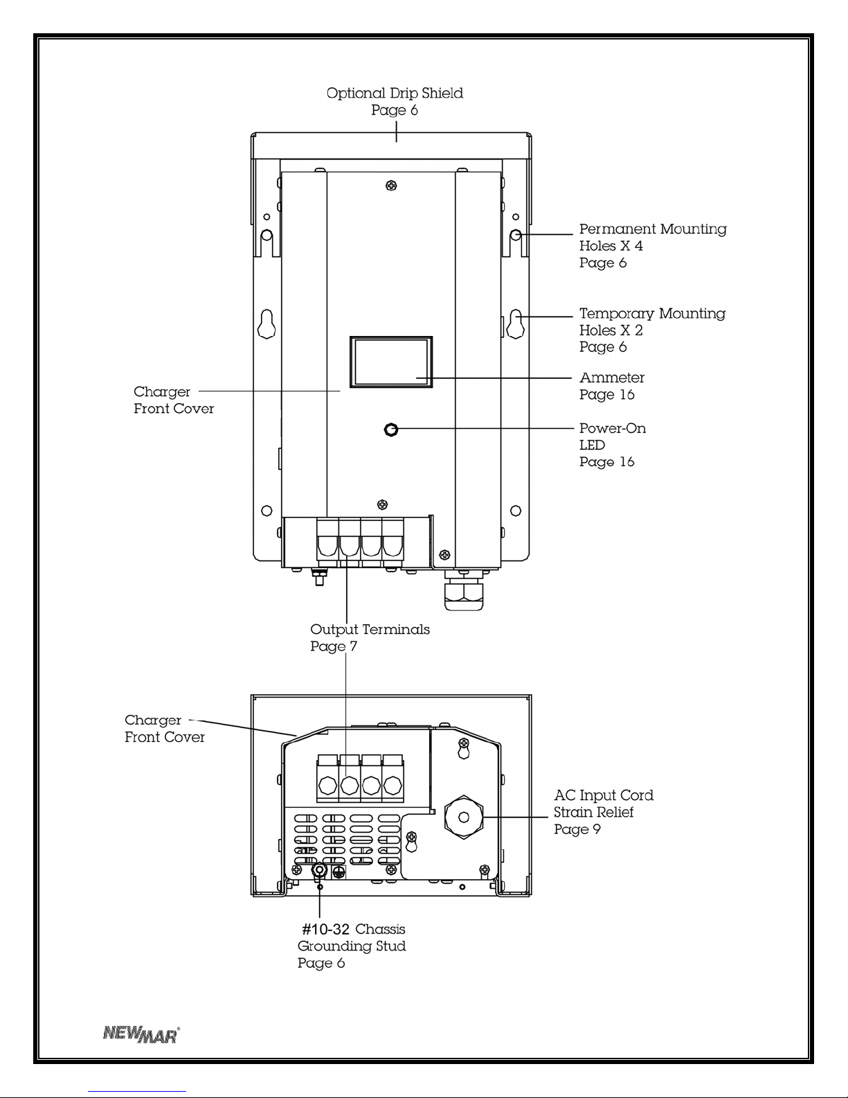
installation.Theprovideddripshieldisinstalledusingtheuppertwomountingscrews.
Notethat,inadditiontothefourpermanentmountingholesintheflanges,thereisaholeineach
mountingflangewhichis“keyhole”shaped.Makeamarkonthewallorbulkheadwhereeachofthe
keyholeslotswillbelocated.Thendriveascrewabouthalfwayinateachofthesemarks.Hangthe
chargerontothebulkheadusingthekeyholeslots.Doingthiswillsaveyoufromhavingtosupportthe
charger’sweightwhileyouaredrivinginthefourpermanentmountingscrews.Note:Thekeyholeslots
maybeusedforadditionalsupportscrewsbuttheyarenottobeusedaspermanentmountingpoints
bythemselves.
IMPORTANT:Althoughthechargerisconstructedofmaterialsandinamannerwhichmakesithighly
resistivetothecorrosiveeffectsofmoistureintheenvironment,thechargerisnotwater‐resistant.

Donotmountthechargerwherethereisapossibilityofwaterenteringtheunit.Evidenceofwater
entryintothechargerwillvoidthewarranty.
D)DCOutputWiring
Note:Onlyqualifiedservicepersonnelshouldaccesstheoutputterminalsofthecharger.
Theinstallerwillneedtoprovideoutputwires.Usethetablebelowtodeterminethecorrectgauge
wire,basedonthelengthofthewirerunfromthechargertothebatteries.
Model LengthofWirefromChargertoBatteries(infeet)
10' 15' 20'
MinimumWireGaugeAWG_____
PT‐24‐8W #18 #16 #14
PT‐24‐13W #16 #14 #12
PT‐14W #12 #10 #10
PT‐25W #10 #8 #6
*BasedonN.E.C.MinimumWireSizeChartandABYC3%VoltageDropChart
ENSURETHATLEADSAREPROPERLYFUSEDATTHEBATTERY.(REFERTOABYC
RECOMMENDATIONS.)
TypicalDCwiringconfigurationsareillustratedinFIGURES1and2.
FIGURE1:SimpleDCWiring(PreferredMethod)
*PerABYCA‐31:ADCchassisgrounding
conductorshallbeconnectedfromthecaseof
thebatterytotheenginenegativeterminalor
itsbus,andmustnotbemorethanonesize
underthatrequiredfortheDCcurrentcarrying
conductorandnotlessthan16AWG.
Note:Thisdiagramdoesnotillustratea
completesystem.RefertoABYCstandardsE‐11
AC&DCelectricalsystemonboats.
IMPORTANT:Installfusesatbatteries
perABYCrecommendations.

FIGURE2:WiringwithBatterySwitch
*PerABYCA‐31:ADCchassisgroundingconductorshallbeconnectedfromthecaseofthebatteryto
theenginenegativeterminaloritsbus,andmustnotbemorethanonesizeunderthatrequiredforthe
DCcurrentcarryingconductorandnotlessthan16AWG.
Note:Thisdiagramdoesnotillustrateacompletesystem.RefertoABYCstandardsE‐11AC&DC
electricalsystemonboats.
IMPORTANT:Installfusesatbatteries
perABYCrecommendations.
AnImportantNoteabouttheDCOutputFuse:DCoutputwiringisprotectedbyaninternallymounted
ATCblade‐typeoutputfuse.Thefuseholderislocatedtothebottomrightofthemeteronthelarge
circuitboard.Toremovethefuseforcheckingorreplacing,removedripshield,thencoverandsimply
pinchthefusebetweenthumbandforefingerandpullfirmlydownward.
ThecurrentlimitingcircuitofthePhaseThreechargershouldpreventthefusefromblowingunder
normaloperatingconditions.Ifthefuseblows,thismayindicateareversepolarityhook‐uporan
internalshort.Ifthebatteryisconnectedtothechargerbackwards,thefuseshouldblowtopreventa
dangerousshortcircuit,howeverdamagetotheinternalcomponentsispossible,aswell.If,after
replacingthisfuse,itblowsagainuponapplicationofpower,returnthechargertoanelectronicsservice
professionalortothefactoryforathoroughinspection.Alwaysreplacethefusewithanotherofthe
sametypeandvalue.ThevaluesfortheDCoutputfusesarelistedinthetableonthenextpage:

DCOutputFuseTable
ModelFuseValue
PT‐14W ATC20amp
PT‐25W ATC30amp
PT‐24‐8W ATC15amp
PT‐24‐13W ATC20amp
E)MultipleUnitParallelWiring
Ifincreasedpowerorsystemredundancyisrequired,asecondchargermaybewiredinparallel.The
unitisdiodeprotectedsoitwillnotbedamagedbyfeedbackfromthesecondunitandcurrentlimiting
willpreventoverloadinginthecaseofafailureofoneoftheunits.
Observethefollowingguidelineswhenwiringaparallelunit.
1)Useonlyanotheridenticalchargermodel.Donotuseadifferentcharger
model,eitherfromNEWMARorfromanothermanufacturer.
2)Wirelengthandgaugeandwirelugsizemustbeidenticalforeachchargerto
ensureproperloadsharing.
3)Wiregaugeforeachchargermustbethesameusedasifasinglechargerwere
wiredintothesystembyitself.
F)ACInputWiring
FortheconvenienceoftheinstalleranACpowercordhasbeenfactoryinstalled.Itisathree‐conductor
strandedtype,16AWG.ThecordisterminatedwithaplugsuitableforstandardUSAoutletsanduses
standardUSAcolorcodingofconductors.
ACinputis"universal".ModelsPT‐14WandPT‐24‐8Woperateinarangeof85‐264VAC,47‐63Hz.No
switchsettingisrequiredforeither115VACor230VACapplications.ModelsPT‐25WandPT‐24‐13W
operateinarangeof90‐132or180‐264VAC,47‐63Hz.Inputvoltageselectionforthesemodelsismade
viaaslideswitchontherighthandsideofthecharger.Itisfactorysetfor115V.For230VAC
applicationsuseaballpointpenorsimilartooltoslidetheswitchupintothe230Vposition.For
reference,theswitchisdownfor115Vandupfor230V.
ACinputforthechargermustberoutedthroughfuseorcircuitbreakeronanACdistributionpanelwith
propersafety/earthchassisgroundinaccordancewithallapplicablelocalcodesandordinances.Caution
(230Vapplicationsonly):IfACinputisderivedfromasourceconsistingoftwoHOTleads(phase‐to‐
phase230VACinputvoltage)anexternalfuseorcircuitbreakermustbeusedtoprotecttheunfused
(formerlyNEUTRAL,nowHOT)lead.
ColorcodingoftheinstalledACcordisasfollows:
Black.................................ACHot(fused)
White.................................ACNeutral
Green................................ACGround(safety,earth)
Ifthefactory‐installedcordmustbereplaceduseacordofequalorlargerAWGratingwithstranded
(notsolid)conductors.RemovetheACinputterminalcoverbyremovingthethreePhillipsheadscrews

securingit.Loosenthestrainrelieftoslidethecoverassemblydownthecordforterminalaccess.Note
theconfigurationofterminalblockwiringasfollows:
FIGURE3:ACInputWiring(asviewedfrombottomofcharger)
(Inmarineapplications)AllchargerwiringshouldbeinstalledinaccordancewithUL,U.S.CoastGuard
and/orA.B.Y.C.regulationsandrecommendations,aswellasallrelevantlocalcodes.SeeREFERENCE
APPENDIXattheendofthismanualforsources.
AnoteabouttheACinputfuse:TheACinputofyourchargerisprotectedbyaninputfusewhichis
locatedinsidetheunit.Duetothecurrentlimitingcharacteristicofthecharger,itishighlyunlikelythat
thisfusewillblowunlessthereissomeothermalfunctionwithinthecharger.Thisfuseisnotuser‐
replaceable.Replacementoftheinputfusemustbeperformedbyaqualifiedserviceperson.
IV)OPERATION
A)ThreeStageChargeRegimen
ThePhaseThreeBatteryChargerutilizesthethreestagechargeregimenwhichiswidelyrecommended
bybatterymanufacturersforallowingthefastestpossiblerechargetimewithoutlossofbatteries’
electrolyte(gelorliquid)whichmaybecausedbysustainedchargingathighervoltages.WhenACpower
isappliedtothecharger,thegreenpower‐onlightwillilluminate.
ThisthreestageregimenisinitiatedeachtimeACisfirstapplied,whendrainedbatteriesaremostlikely
tobeencountered,andproceedsslowlyorquicklythrougheachstagedependingonthebattery’s
relativestateofcharge.(Thisalsooccurswhenthereinitializebuttonontheoptionalremotepanelis
activated;seeRemotePanelOptionsectionformoreinformation).Thechargeregimenproceedsas
follows:
1)BulkPhase:Whenbatteriesaresignificantlydischargedthechargerrespondsinitiallybydeliveringa
highamountofDCcurrent,atornearthecharger’smaximumratedoutput,inordertorapidlyreplenish

them.Itisduringthisstagethatchargingcurrentismaintainedatahighlevelasbatteryvoltage
increases.Bulkchargingcontinuesuntilbatteryvoltagereachesthe“charge”voltagelevel(where
batteriesareatabout75‐80%ofcapacity).Acurrentlimitcircuitpreventschargeroverloadduringthis
maximumoutputstage.Atthispointthechargerswitchestothesecondstage.
2)AbsorptionPhase:Duringthissecondstageofthechargecycle,batteryvoltageismaintainedatthe
“charge”voltagelevel.Outputcurrentbeginstotaperoffasthebatteryplatesbecomesaturated.
Chargevoltageismaintaineduntilthecurrentsensingcircuitdetectsthatoutputcurrenthastaperedto
about5‐15%ofchargerrating*.Atthispointthebatteriesareatabout95%offullchargeandthe
PhaseThreechargerswitchestothethirdandfinalstageofthechargecycle.
*Note:Theabsorptionphasemayalsobeendedbythetime‐outcircuit.SeesectionBfollowingfora
completeexplanationofthepurposeandfunctioningofthetime‐outcircuit.
3)FloatPhase:ForextendedbatterylifethePhaseThreethenautomaticallyswitchestoalowerfloat
voltagelevel.Thisfloatchargekeepsbatteriesatpeakconditionwithoutovercharging.Thechargermay
beleftinthisstageforlengthyperiodsoftimewithoutattention(thoughperiodicchecksofelectrolyte
levelinfloodedbatteriesisrecommended).Itisnotnecessaryorrecommendedtoshutthechargeroff
whenthisstageisreached.
AtypicalthreestagechargingcycleisillustratedinFIGURE4.
FIGURE4:TypicalChargerOutputGraph(intobatterywithoutload)
*Approximately10hoursmaximumatfactorysetting
Thebulk/absorptionstageslastapproximately10hoursmaximumatfactorysetting.
Note:Ifaloadisappliedduringtheabsorptionphase,thechargermayreverttothebulkphase
dependingonthetotalcurrentdraw.Whenthechargerswitchestothefloatphase,itwillremaininthat
phaseregardlessofcurrentdraw.Thechargerisstillabletodeliverfulloutputcurrentwheninthefloat
phase.Tore‐initializethethreestageprocessshutthechargeroffmomentarily,thenbackonagain(or
pressthereinitializebuttonontheoptionalremotepanel)

B)Time‐OutCircuit
Batterieshaveatendencytolosetheirelectrolyteandmaybedamagediftheyaremaintainedforlong
periodsoftimeintheelevatedvoltageoftheabsorptionphase.Therefore,thePhaseThreeCharger
employsaspecialtime‐outcircuit.ThiscircuitisinitializedeachtimeACisfirstappliedtothecharger(or
whenthereinitializebuttonontheoptionalremotepanelisactivated)andrunsforapre‐setinterval
beforeforcingthechargertogointothefloat(lowervoltage)mode.Thefunctioningofthecharger
duringthisintervalisasfollows:
Ifthecurrentdemandofthebatteries/loadfallsbelow5‐15%ofthecharger’soutputcapacitypriorto
thecircuittiming‐out,thechargerwillautomaticallyswitchtothefloatmode.Ifdemandrisestoabout
10‐20%ofchargeroutputcapacity,itwillreturntotheelevatedoutputvoltageoftheabsorptionphase.
Thisswitchingbackandforthbetweenmodesmayoccuruntilthecircuittimes‐out(8‐10hoursafterAC
isfirstapplied),afterwhichthechargerwillremainatfloatvoltage,untilthecircuitisre‐initialized,
eitherbyturningthechargeroffandthenonagainorbypresssingthere‐initializebuttononthe
optionalremotepanel.
InstallationNote:Thetime‐outcircuitofthePTchargerhasbeensetatabout8‐10hours,whichis
appropriateforbatterysystemswithinthecapacityrangespecifiedonthefrontpanelofthecharger.If
thechargerisusedwithabatterysystemwithacapacitynear(oroutside)theupperorlowerrangesof
thespecifiedrangeofthecharger,adjustmentoftheinternallylocatedtime‐outcircuitadjustmentpot
mayberecommended.Theprocedureisasfollows:
(Caution:EnsureACinputhasbeendisconnectedbeforeproceeding)
1)Removethetwophillipsheadscrewsonthefrontpanel(bottomrightandjustabovetheoutput
terminals),aswellasthetwophillipsheadscrewsoneachsideoftheunit.
2)Carefullyliftthemaincoveroffofthechargerbaseifinstalled.Itisnecessarytoremovethedrip
shield.
3)Locatethepotentiometerlabeled"TIMERADJ"onthechargerfunctioncircuitboardlocatedonthe
lefthandsideofthecharger.
4)Usingasmallflattipscrewdriver,turnthepotentiometer:
*clockwisetoincreasetheamountoftimethechargerremainsintheabsorption
modebeforetimingout
*counterclockwisetodecreasetheamountoftime.
Theapproximaterangesareillustratedonthenextpage.

FIGURE5:AdjustingtheTime‐outCircuit
Note:Oncethetime‐outcircuithasputthechargerintofloatmode,thechargerwillremaininthis
mode.SincethePhaseThreeChargeriswellregulated,itisabletodeliveritsfullratedoutputcurrent
inthismodeandbatterydischargewillnotoccur(providedloadcurrentdoesnotexceedcharger
ratingandoutputwiringisproperlysized).
C)Gel‐Cell—Flooded/AGMSwitch
Accordingtomostbatterymanufacturers,theidealchargeregimenforgel‐cellandflooded(wet)lead‐
acidorAGM(AbsorbedGlassMat)batteriesdifferssomewhat.
Thegelledelectrolyteinasealedbatterymaybelostordamagedbyhighvoltageand,oncelost,cannot
bereplacedasitcanwithawetleadacidbattery.Manufacturersofgel‐cellsusuallyrecommendan
idealchargevoltagewhichisslightlylowerforagel‐cellthanalead‐acidbattery.(Thechargeregimen
recommendedforAGMbatteriesistypicallysimilartothatoffloodedlead‐acidbatteries.)
However,whenthechargerisinthefloatvoltagemodeoverlengthierperiodsoftime,gelledelectrolyte
inasealedbatteryisnotsusceptibletoevaporation,asisthenon‐immobilizedelectrolyteofawetlead
acidbattery.Thisevaporationcanbeacceleratedbytheappliedvoltage.Consequently,theidealfloat
voltageisslightlyhigherforagel‐cellthanalead‐acidorAGMbattery.
ThebatteryselectorswitchislocatedontheChargerFunctionBoard.Theidealcharge/floatregimenhas
beenprogrammedintothePhaseThreeChargerforeithersealedgel‐cellorfloodedlead‐acid/AGM
batteries.Simplymaketheproperselectionforyourbatterytypeviatheslideswitchonthefrontofthe
charger.Theswitchpositionsareindicatedoneithersideoftheswitchaccessport.Useaballpointpen
orsimilarobjecttoslideitintothecorrectposition.SlidetheswitchdownforLead‐Acid,Sealedand
AGM,andupforGel‐Cell.
Note:Awidevarietyofbatteriesarenowavailablewhichdonotconformtoconventionaldescriptions
as“gel‐cell”or“lead‐acid”.Youareadvisedtoconsultthemanufacturerofyourparticularbatteryasto
properchargingregimen,andusethebatterytypeselectionswitchsettingwhichmostcloselyconforms
totherecommendedvoltages.
SeetheSPECIFICATIONSsectionfortheactualpresetchargeandfloatvoltagesforeachmodel.
D)RemoteMonitorPanelOption
ARemoteMonitorPanelisavailablefromNEWMAR(modelRP)whichwillenableyoutomonitorthe
charger’sstatusat‐a‐glancefromaremotelocation.RedandgreenL.E.D.’sindicatewhetherthecharger
isinthebulk,absorptionorfloatphaseofthechargecycle.Inaddition,thepanelfeaturesare‐initialize

button,which,whenpressed,willcausethechargertorestartthethreephasecycle.Thisresetsthe
time‐outcircuit(seesectionB:Time‐outCircuit,above).Note:Thechargermaynotstayinthebulkor
absorptionmodeafterpressingthere‐initializebutton.Ifbatteriesareatornearfullcharge,thecharger
willquicklyreverttothefloatmode.
Thepanelcomespre‐wiredwith30'ofcableand4mountingscrews.Simplyinstallthepanelatthe
desiredlocationandinserttheplugontheendofthecableintotheremotepaneljackwhichislocated
andidentifiedontheleftsideofthecharger.Note:Inadvertentlyputtingtheremotepanelplugintothe
tempcompensationjack(orviceversa)willnotharmthecharger.Ifthepaneldoesnotappearto
functioncorrectly,checktoseethatitispluggedintothecorrectjack.
Incaseadditionalcablelengthisrequired,extensioncablesarecommonlyavailablefrommost
electronicssupplyretailerssuchasRadioShack/Tandy.Requesta6conductormodular‐to‐modularline
cord(partnumber279‐422,25feetlong)and6pinmodularin‐linenon‐reversingcoupler(279‐423).
E)TemperatureCompensationOption
Becauselowbatterytemperatureincreasesresistancetochargingandhighbatterytemperature
reducesimpedance,requiringalowerchargevoltage,theidealchargingvoltagewillvarydependingon
thetemperatureofthebattery’senvironmentwhenitisbeingcharged.
Ifachargerhasafixedoutputvoltagewhichisidealat,say72°F,thatsameoutputmaycauseabattery
chargedinaconsistentlyhightemperatureenvironmenttobeovercharged,resultinginexcessivelossof
electrolyte.Conversely,ifthebatteriesareinaconsistentlycoolenvironment,theymaybechronically
undercharged,resultinginsulfationofthebatteryplates.Eitherofthesetwoconditionswillshorten
batterylife.
Therefore,thePhaseThreechargerisdesignedtoutilizeanoptionalremotesensor(availablefrom
NEWMAR;modelTCS‐12/24)whichprovidesautomatictemperaturecompensation.Theremotesensor
willsignalthechargertofinetuneitsoutputvoltagesothatitisproperlymatchedtothetemperature
ofthebattery/batteryenvironment.Theadjustmentrateisapproximately‐5mVpercellper°C.(Note:
Thetemperaturecompensationoptionisstronglyrecommendedforsealed,valve‐regulated,AGMor
gel‐cellbatteries.)
Theremotesensorisprovidedwith30'ofcable.Oneendofthecableispluggedintothetemperature
compensationjackwhichislocatedontheleftsideofthecharger.Thelocationoftempsensorjackis
identifiedonthefrontpanel.
Incaseadditionalcablelengthisrequired,extensioncablesarecommonlyavailablefrommost
electronicssupplyretailerssuchasRadioShack/Tandy.Requesta6conductormodular‐to‐modularline
cord(partnumber279‐422,25feetlong)and6pinmodularin‐linenon‐reversingcoupler(279‐423).
Thesensoritselfshouldbemountedontheinsideofthebatterybox,ormoreideally,mountedonto
oneofthebatteriesusingaclamporasmallamountofsilicon‐typeadhesive.Thesensorhasaholein
thecenterwhichwillaccommodatea#6screw.Ifyouhaveaccesstotheexteriorofawallofthe
batterybox,youmaydrillaholeinthewalloftheboxandrunthescrewthroughtomountthesensor
ontotheinteriorwall.Usecautionwhendrillingsothatyoudonotaccidentallypuncturethecaseofany
batteryinsidethebox.

Importantnote:Whenwiringmultiplechargersinparallel(seesectionE)andusingthetemperature
compensationoption,youmustuseaseparatesensorforeachcharger,andthesensorsmustbe
mountedclosetogetherinthesamebatteryboxoronthesamebatteryforproperoperation.
Withoutthetemperaturesensorinstalledtheoutputofthechargerwillbeatthenominalvoltages
specifiedinthechartonthefollowingpageat72°F(22.2°C).Theabsorption/floatoutputvoltage
settingsatthattemperaturearelistedinthechart.
Toprovidesomeexampleswhichclarifytheeffectofthetemperaturecompensationsensor,thechart
liststheabsorption/floatoutputvoltagesofthechargerwhenbatteriesareat72°F(orwhenthesensor
isnotinstalled),andatcold(50°F)orhot(90°F)batterytemperatureswiththesensorinstalled:
Battery OutputVDC:12VoltModels OutputVDC:24VoltModels
Temperature
Charge Float
Charge Float
⁰F⁰CGel‐Cell
Lead‐
Acid
Gel‐
Cell
Lead‐
AcidGel‐Cell
Lead‐
Acid
Gel‐
Cell
Lead‐
Acid
501014.414.614.013.828.829.228.027.6
7222.214.0*14.2*13.6*13.4*28*28.4*27.2*26.8*
9032.213.713.913.313.127.427.826.626.2
F)EqualizeTimerOption
Somemanufacturersoffloodedlead‐acidbatteriesrecommendachargingprocessknownas
equalizationforextendedbatterylife.Thisprocessinvolvesoccasionallychargingawetlead‐acidbattery
ataveryhighvoltageforashortperiodoftimeinordertocompletelyde‐sulphateeachofthebattery
plates,essentiallyequalizingtheirvoltage.TheinstallerofthePhaseThreechargermaychoosetowire
inthisoptionatthetimeofinstallation.
Note:TheequalizationprocessisforFloodedLead‐Acidbatteriesonly!
Theequalizecircuit(connectorlocatedinsidethePTcharger)shouldbewiredthroughamanualor
electrictimerwhichprovidesaclosedcontactwhenengagedandanopencircuitwhentimedout(SPST
—SinglePoleSingleThrow).Donotuseamanuallyoperatedswitchforactivatingtheequalizecircuit.
Thisisbecauseunlessthechargerisrevertedtoasafefloatvoltageinatimelymanner,thebatterieswill
almostcertainlybedamagedordestroyed.Thetimercontactsshouldbea0‐12hourtype,capableof
carryingaminimumof100mAat5VDC
CAUTION:Donotinstallthetimerinanarearequiringingnitionprotectedequipmentunlessithas
beencertifiedtomeetignitionprotectionrequirements.
TheequalizationcircuitofthePhaseThreechargerboostsoutputvoltagetoapproximately8%above
floatvoltage.Refertothebatterymanufacturer’sinstructionswhendecidingtheappropriatetime
periodsettingforthisvoltagetoachieveproperequalization,whileensuringbatteriesarenotdamaged
byincreasedbatterytemperature.Thisinstallationshouldonlybeperformedbyaqualifiedtechnician.
Installingthetimerrequiresamatingconnectorwithdualwireswhicharepluggedintoajackonthe
internalchargerfunctioncircuitboard.Theconnector/wireassemblyisavailablefromNEWMAR.

Requestpartnumber873‐3716‐0,CFBEqualize2pinassembly.Proceedwiththeinstallationasfollows:
(Caution:EnsureACinputhasbeendisconnectedbeforeproceeding)
1)Removethetwophillipsheadscrewsonthefrontpanel(bottomrightandjustabovetheoutput
terminals),aswellasthetwophillipsheadscrewsoneachsideoftheunit.
2)Carefullyliftthemaincoveroffofthechargerbase.Itisnotnecessarytoremovethedripshield.
3)Locatethetwo‐pinheaderlabeled"J2"justoverthecut‐outonthebottomofthefront‐facingcharger
functioncircuitboard.Insertthematingconnectorandroutethetwocontrolwiresthroughthevent
holeonthebottomofthecharger.Connectthewirestothetimer.
4)Replacethechargercover.Whenloweringthecoverontothebase,avoiddamagingconnectorson
thecharger/functionPCB.Ifused,re‐installthedripshield.
G)OutputAmmeter
Thiswillindicatetotalchargingoutputcurrentforallbatterybanksconnected.
H)Power‐OnIndicator
ThisgreenLEDwillglowwheneverthechargerisreceivingACpower.
V)APPLICATIONNOTES
A)StartUp
1)Beforepoweringupyourcharger,checkfortightelectricalconnectionstoeachbatteryinyour
system.SwitchoffanyDCloadsonthebatteries.ApplyACpower.ObservetheDCammeteronthefront
panel.ThismeterdisplaysthetotalDCoutputofthecharger,throughallbanks.Itwillgivesome
indicationoftheoverallstateofchargeofyourbatteries.Ifthemeterisreadingmid‐scaleorhigher,itis
anindicationthatthebatteriesareinarelativelylowstateofcharge.Thecharger,sensingthis,is
supplyinghighcurrenttothebatteries.Ifthemeterneedleisatornearthebottomofthescalethe
batteriesareatornearingfullcharge.
2)Applyaloadtothechargerbyswitchingonsomelights,apumporsomeotherDCappliance.Observe
thechargermeter.Itshouldreadapproximatelythesameastheexpectedcurrentdrawofthe
appliance.Ascurrentisdemandedfromthebatterysystem,thechargerwillautomaticallyincreaseits
outputinresponsetotheincreasedloaddemand.Whenloadcurrentexceeds10‐20%ofthecharger’s
ratedcapacity,thechargerwillgointotheabsorptionmodeandremainthereuntilcurrentdropsbelow
5‐15%ofcapacityoruntilthetime‐outcircuitcycleiscomplete.
B)ConstantVersusOccasionalUse
Ingeneral,itisrecommendedthatthechargerbeleftconnectedcontinuouslytotheACdistribution
systemsothatitwillbeinoperationwheneverACisavailable.Thiswillmaintainbatteriesatpeak
voltageandwillautomaticallycompensateforthenaturalself‐dischargeofthebatterysystem.Whena
loadisappliedtothebatterysystemthecharger’soutputwillautomaticallyincreasetosupplythe
currentwhichwouldotherwisedrawbatteryvoltagedown.Repeatedlyallowingbatteriestobecome
completelydischargedbeforerechargingwillgreatlyshortentheirlife.Leavingthechargeron
continuouslywillpreventthis.

Whiletheoutputregulationofthechargerwillminimizebatterygassingandwaterloss,monthlychecks
oftheelectrolytelevel(forwetleadacidbatteries)arestillstronglyrecommended.Somewaterlossis
aninevitableaspectofthechargingprocess,andmaintainingthecorrectelectrolytelevelinyour
batteriesisthemostimportantthingyoucandotoassuretheirmaximumperformanceandlonglife.
C)ProperLoadSizing
ThePhaseThreeChargerisratedforcontinuousduty(e.g.,modelPT‐14Wisratedat14amps
continuous,PT‐25at25ampscontinuous,etc.).Whilethechargercannotbedamagedbyoverloadsthat
exceedthiscontinuousrating,excessiveloaddemandsmaydrawbatteryvoltagedownfasterthanthe
chargercanresupplyit.Ifbatteryvoltagecontinuestodropandtheoutputcurrentisatmaximumwhile
thechargerisinservice,checktoseethatyouraverageDCloadsarenotexceedingthecharger’srated
output.Iftheyare,youmaywishtoconsideraddinganotherchargerinparalleltoprovidesufficient
powerforyourrequirements.(SeesectionIII‐E,MultipleUnitParallelWiring.)
D)OperationwithEngine
Itisperfectlyacceptabletoallowthechargertoremainonwhentheengineisstartedandwhileitis
running.ThecurrentlimitfeatureofthePhaseThreeChargerwillprotectagainstanydamageduetothe
highcurrentdemandsofenginecranking.Outputdiodeswillpreventanyback‐feedofcurrentintothe
chargerfromthealternatorwhiletheengineruns.
Asthealternatorstartstochargethebattery,thechargeroutputwilldecrease.Whenthebattery
voltageexceedstheratedoutputvoltageofthechargeritwillshutoffandstayoffaslongasthe
batteriesareinthishighstateofcharge.Ifthebatteryvoltageshoulddropbelowthecharger’srated
outputvoltageitwillautomaticallyreturntoservice.
E)OperationasaDCPowerSupply(stand‐aloneDCpowersource)
Mostbatterychargersarenotsuitableforpoweringelectronicdevicesdirectly,withoutabattery
attachedtotheoutput,asthehighrippleandpulsingDCoutput(i.e.,rectifiedACoutput)caninterfere
withtheoperationofthedevice.However,thischargeremploysacircuitthatproducesanextremely
well‐filteredDCoutput.ThereforeitisabletopowervirtuallyanyDCpowereddevice(withintheunit's
rating)withoutthebatteryattachedin‐line(if,forinstance,thebatterymustberemovedforany
purposeandACisstillavailable).AllbutthemostsensitiveDCpoweredelectronicdeviceswillfunction
asnormallyasifpoweredbyabattery.Inaddition,thecurrentlimitingcircuitryenablesthechargerto
handlethehighstart‐upsurgesassociatedwithinductiveloads.
VI)SPECIFICATIONS
Model PT‐14WPT‐25WPT‐24‐8WPT‐24‐13W
InputVAC(50‐60Hz.):85‐26490‐132or 85‐26490‐132or
180‐264 180‐264
InputAmps@FullLoad:
@115VAC2.86.52.86.5
@230VAC1.441.44
P.F.Rating: .95@230V.7.95@230V.7
OutputVoltage(Nominal):12122424
OutputAmps(Continuous):1425813

Specifications(Cont.)PT‐14WPT‐25WPT‐24‐8WPT‐24‐13W
OutputBanks: 3333
BatteryCapacity(Amp‐Hours):28‐14050‐25016‐8026‐130
Weight(Lbs./Kg.):7.58.57.58.5
ComplianceReferences: CG,CE CG CG,CE CG
ComplianceReferences*:
CGIgnitionprotectedperUSCGCFR183.410
CECarriestheCEMark
*NumerousotherSafetyandEMCcompliancesmayalsoapply.Contactfactoryiffurther
complianceinformationisrequired.
TemperatureRating(allmodels):
‐10°Cto+60°C;Deratelinearlyfrom100%@50°Cto60%@60°C
NominalOutputVoltagesatGel/FloodedSwitchSettings(withoutTemperatureCompensation
optioninstalledorat22.2°C(72°F)withTemperatureCompensationoptioninstalled):
12VoltModels 24VoltModels
Charge Float Charge Float
Setting@50%load@.5ampload@50%load@.5ampload
Gel‐Cell14.0VDC13.6VDC 28.0VDC27.2VDC
Flooded/AGM14.2VDC13.4VDC 28.4VDC26.8VDC
TemperatureCompensation:‐5mVpercellper°C.Sensorsuppliedwith25'cableandplug‐in
connector
RemotePanel,ModelRP:LED'sindicatechargeroutputstage.Buttonallowsmanual
reinitializationofthreestagechargecycle.Suppliedwith25'cableandplug‐inconnector.Panel
dimensions:3"Hx4.75"W
Protection(allmodels):Input/OutputFuses,CurrentLimiting,ThermalProtection,ForcedAir
Cooling,DripShield
CaseSize:11.10”H*x7.75”Wx4.75”D*
*Add1.15”(2.92cm)toheightand.95”(2.41cm)todepthfordripshield
VIITROUBLESHOOTING
Note:Thesechargersincorporateself‐containedACtoDCconversionmoduleswhichutilizenumerous
automaticprotectioncircuits.TheACinputfusewhichprotectsinternalwiringishousedinsidethe
chargerwiththemodule.Undermostcircumstancesthefusewillfailonlyifthechargerhasaninternal
fault.Hence,theyarenotintendedtobeuser‐replaceableandanyconditionwhichhascausedablown
ACfusewilllikelyrequirerepairofotherinternalcircuitrybyaqualifiedtechnician.Ifanapparent

chargerfaultcannotbecorrectedusinganyoftherecommendationsinthissection,thechargershould
bereturnedtothefactoryorplaceofpurchaseforinspectionandrepairorreplacement.
PROBLEM POSSIBLECAUSE SOLUTION
A.Batteriesnotcoming1.Extremelydischarged 1.Turnoffalld.c.loadsand
uptofullchargebatteriesrequiringlong allowcharger24‐48hoursto
rechargetimerechargebatteries
2.Chargerlimitingitsoutput 2.Reduced.c.loadand/or
duetooverloadorover‐ determinecauseofover‐
temperatureconditionstemperaturecondition(see
sectionIII‐B,Location)
B.Chargercontinuestocharge 1.d.c.loadconnectedto 1.Turnoffmainbatteryswitch
at3ampsormore—doesnot batteriesdrawingcurrent(not tod.c.electricalpanelorturn
taperbackaproblemcondition)ofalld.c.loadsifyouwishto
confirmchargerwilloutput
minimalamperagetofully
chargedbatteries
2.Badcellinoneofthe 2.Checkforshortedcellinwet
batteriestowhichthecharger lead‐acidbatteriesusinga
isconnectedhydrometer.Referto
manufacturerfortesting
maintenance‐freebatteries
C.Nochargeroutput,even Blowninputfuseorother Returntoservicingdealerfor
whenallconnectionshave internaldefectfailureanalysisorcontact
beenchecked,a.c.isapplied NEWMARforReturnAuthorization
tothecharger,andd.c.loadis Number
appliedtothebatteries
D.Reversepolarityconnection d.c.outputfuseandother Replaceoutputfusewithlike
hascausedchargertohaveno internalcomponentslikely typeandvalue.Ifstillnooutput,
outputblownreturntoservicingdealerfor
failureanalysisorcontact
NEWMARforReturn
AuthorizationNumber
E.Highvoltagemeasuredacross 1.Batteriesnotconnectedto 1.Checkfortightconnectionof
chargeroutputterminalscharger.Itisnormaltoread1/2 chargingleadstobatteries
volthigheracrossanyoutputbank
whennobatteriesareconnected
2.Equalizefunctionisactivated2.Checktoverifyproperinstal‐

lationandoperationofequalize
timer.
3.Tempprobenotpluggedin3.Checkplugisseatedproperly,
fully,defectiveprobereplaceprobeifdamaged
F.Chargerwillnotstayinbulk/Batteriesatornearingfullcharge Verifyproperoperationbycycling
absorptionphasewhenre‐initial‐ (notaproblemcondition)a.c.offandon(orpressreinitialize
izebuttononremotepanelis buttononoptionalremotepanel)
pressed. thenapplyingalarged.c.load
FactoryContactInformation
Ifaproblemwithyourchargerpersistsafteryouhaveappliedtheabove‐outlinedsolutions,orifyou
haveanyquestionsabouttheinstallationandproperoperationofyourcharger
Wewillbehappytoconsultwithyoutoresolveanyproblemyoumayhave.Ifitappearsthecharger
mustbereturnedtothefactoryforrepairwewillissueaReturnMaterialsAuthorizationatthattime.
VIII)BATTERYCARETIPS
Regularmaintenanceandpropercarewillassureyoureliableservicefromthemostdepended
uponandsometimesmostneglecteditems,yourbatteriesandbatterycharger.NEWMAR
batterychargersaredesignedtokeepyourbatteriesfullychargedbutyourbatteriesalsoneed
properregularmaintenancetoprovideamaximumlifeofservice.
ALWAYSREADANDFOLLOWTHEBATTERYMANUFACTURER’SINSTRUCTIONS
BatteryInstallation
Batteriesmustbesecurelymountedtopreventthemfromfallingoverwhenthevehicleorboat
isinmotion.Aloosebatterycandoseriousdamage.Batteriesshouldbemountedinabattery
boxtocontainanyacidspill.Batteriesgiveoffacertainamountofhydrogengaswhentheyare
charging.Whenconcentrated,thisgasishighlyexplosive.Thereforemakesuretheyareinan
accessibleplacewithadequateventilationforanyhydrogengasdischarge.
CleaningBatteries
Dirtandelectrolytesaltscanbuilduponthetopofyourbatteries.Thisaccumulationconducts
electricitystoredinthebatteryandcancausethebatterytodischargebyitself.Therefore,at
leasttwiceayear,itisagoodideatodisconnectthebatterycablesandscrubthebatterywitha
bakingsodasolution.Rinsewithfreshwateranddrywithacleancloth.
This manual suits for next models
4
Table of contents
Other NewMar Batteries Charger manuals

NewMar
NewMar PHASE THREE PT-14 User manual

NewMar
NewMar Phase Three PT-7 User manual

NewMar
NewMar Guided Wave 12-1200IC User manual

NewMar
NewMar PT-24-45W User manual

NewMar
NewMar 12-1800IC User manual

NewMar
NewMar SOL 20 User manual

NewMar
NewMar PM-12-80 Installation instructions

NewMar
NewMar PT-24-20W User manual

NewMar
NewMar Phase Three PT-70a User manual

NewMar
NewMar PT-24-45W User manual