Phone: 714-751-0488
Fax: 714-957-1621
www.newmarpower.com
P.O. Box 1306
Newport Beach,
California 92663
4
A) Materials Provided
The inverter/charger is provided with an installation kit containing the following:
(1 ea.) Hex wrench, 3/8"
(1 ea.) Warning label for AC distribution panel
(1 ea.) Installation/Operation Manual
(1 ea.) Customer satisfaction/warranty card
Please verify that these items have been included with the packaging. For any missing items,
contact the factory. Upon completion of the installation, please fill out the warranty card and
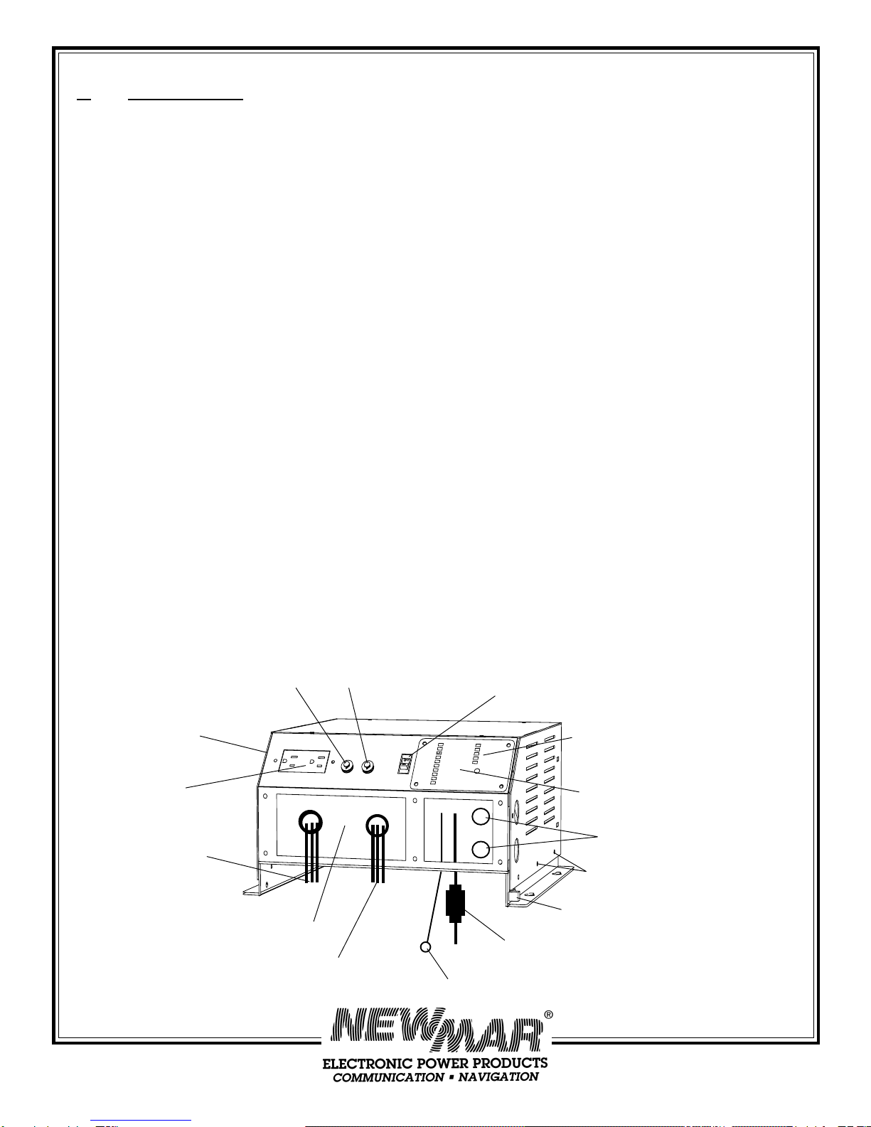
return it to the factory. (Be sure to include the serial number of the unit, located on the top
of the housing.)
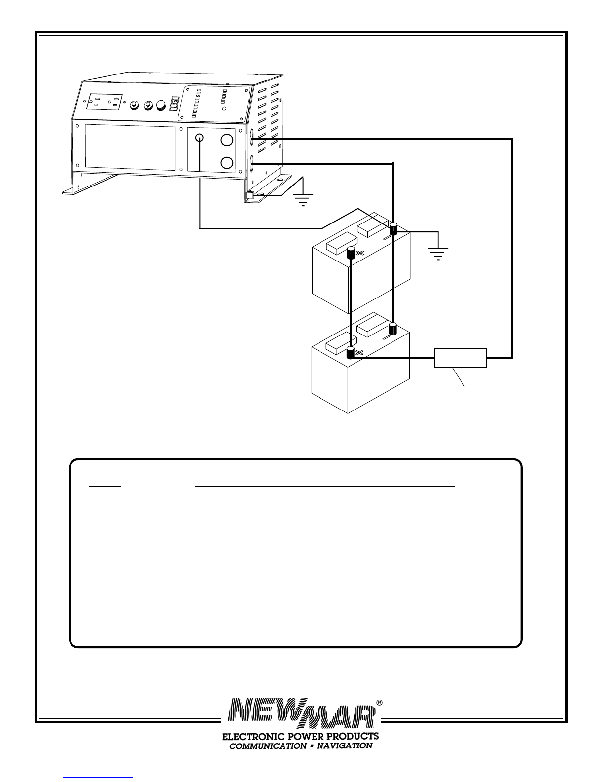
B) Location
The inverter/charger should be located as close to the batteries as possible, ideally no more
than about 4-6 feet. The maximum allowable distance is 20 feet. Do not mount the unit
directly over the batteries as battery fumes may cause excessive corrosion. WARNING: The
inverter/charger is not ignition protected so it must not be located in an area containing gasoline
engines or the like, nor in any other area where ignition protected equipment is required. The
area should be well ventilated and free from moisture, exhaust manifolds and battery fumes.
Do not locate the unit where water, spray or condensation can occur, as this will shorten its
life. It should not be located where there is a possibility of dust or debris being drawn into
the unit through the fan. A minimum of 2" clearance around the unit is recommended for
proper cooling.
If the inverter/charger is located in an extreme heat area, such as an unventilated engine
room, and maximum operating temperature is exceeded, an automatic thermal protection
circuit will shut the unit completely off. It will automatically return to service when it has
cooled sufficiently, however this thermal cycling will shorten the life of the inverter/charger,
so if this condition occurs repeatedly, it should be relocated. For optimum performance and
longer life the unit should not be located in an area of high temperature.
C) Mounting
The inverter/charger may be mounted on either a horizontal or vertical surface; performance
will be unaffected by its orientation, however, per UL safety recommendations, when
mounted vertically the front panel controls should be facing downward. It may be mounted
on either a metal or non-metal surface. Four 1/4" screws (wood or machine screws, depend-
ing on mounting surface) with washers are required to secure the unit to the mounting
surface.
For vertical (bulkhead) mounting applications: Note that, in addition to the four permanent
mounting holes in the flanges, there is a hole in each mounting flange which is “keyhole”
shaped. This is provided to ease vertical installation. Make a mark on the wall or bulkhead
where each of the keyhole slots will be located. Then drive a screw about halfway in at each