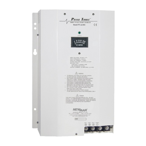
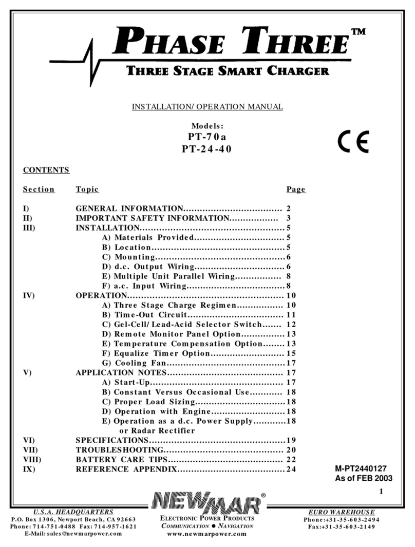
NewMar PT-24-45W User manual

P.O. Box 1306, Newport Beach, California 92663 • Phone: 714-751-0488 • Fax: 714-957-1621 • E-Mail: techservice@newmarpower.com
www.newmarpower.com
1
M-PT-W-LNGFM
As of Feb 2007
Phase Three
Three Stage Smart Charger
Installation/Operation Manual
Models: PT-24-45W, PT-24-60W, PT-24-95W, PT-32-25W, PT-32-70W
TABLE OF CONTENTS
Section Topic Page
QUICK REFERENCE DRAWING 2
I) GENERAL INFORMATION 3
II) IMPORTANT SAFETY INFORMATION 3
III) INSTALLATION 4
A) Materials Provided 4
B) Location 4
C) Mounting 4
D) D.C. Output Wiring 5
E) A.C. Input Wiring 6
F) Multiple Unit Parallel Wiring 8
G) Gel-Cell/Lead-Acid Selector Switch 9
H) Temperature Compensation Option 10
I) Alarm Contacts 10
IV) OPERATION 10
A) Three Stage Charge Regimen 10
B) Time-Out Circuit 11
C) Status Indicators 11
V) APPLICATION NOTES 12
A) Constant Versus Occasional Use 12
B) Proper Load Sizing 12
C) Operation with Engine 12
D) Cooling Fans 12
1) Operation
2) Maintenance
E) Current Limit Circuit 13
H) High Temperature Output Reduction Circuit 13
VI) TROUBLESHOOTING 13
VII) SPECIFICATIONS 14
VIII) BATTERY CARE TIPS 15
X) UNIT DIMENSION DRAWING 16
XI) REFERENCE APPENDIX 17

P.O. Box 1306, Newport Beach, California 92663 • Phone: 714-751-0488 • Fax: 714-957-1621 • E-Mail: techservice@newmarpower.com
www.newmarpower.com
2
Quick Reference Drawing
Optional Drip Shield
Pg. 4
Permanent Mounting
Holes (X4)
Pg. 4
Temporary Keyhole
Mounting Holes (X2)
Pg. 4
Power LED
Pg.11
Charger Status LED
Pg. 11
Charger Front Cover
Pg. 5
Cover Mounting
Screws (X4)
Pg. 5
LED Bar Graph Output
Amperage Indicator
Pg. 11
Gel Cell/Lead Acid-
AGM Battery Type
Selector Switch Pg. 9
Exhaust Cooling Fan & Filter
Pg. 12
Cover Mounting Screws (X4)
Pg. 5
Optional TP Temperature
Probe Cable Feed-Thru Pg. 10
AC Fail & DC Fail
Alarm Contacts Pg. 10
Charger Front Cover Pg. 5 Optional Drip Shield Pg. 4
Output Terminal Cover
Pg. 5
Output Terminals
Pg. 5
AC Input Cable Entry/
Strain Relief
Pg. 6
1/4 - 20 Chassis
Grounding Stud Pg. 5

P.O. Box 1306, Newport Beach, California 92663 • Phone: 714-751-0488 • Fax: 714-957-1621 • E-Mail: techservice@newmarpower.com
www.newmarpower.com
3
I) GENERAL INFORMATION
Your Phase Three Series Battery Charger uses the latest
microprocessor controlled three stage charging technology to
optimize the life and enhance the performance of marine, mobile
and fixed site battery systems and is housed in a rugged stainless
steel case designed to withstand harsh environmental conditions.
This charger line has been developed in response to demand for
increasingly sophisticated charger performance, as the technology
of new battery types and applications advances. The Phase Three
combines high power performance with adaptability to varied
charging requirements and environmental conditions. Batteries are
quickly and properly charged and maintained, assuring their long
life and optimum performance.
Following is brief listing of some of the more important features/
options of your Phase Three Charger. Each is fully detailed later in
this manual:
• Micro-processor controlled three stage “smart” charging—bulk,
absorption, float—for optimum performance and long life of large
battery systems.
• Precision regulated, high power output for rapid rejuvenation of
medium-to-large 24 and 32 volt battery systems; maintain
batteries at peak voltage, even with high D.C. system loads
present.
• Gel-Cell/Flooded lead-acid switch selects optimum charge/float
voltages based on battery type.
• Three diode isolated output banks; (LED Bar Graph ammeter
indicates total output current.)
• Optional sensor adjusts output for optimum voltage based on
battery temperature.
• Current limiting—prevents damage from overloading.
• L.E.D. and audible indicators show charger status and diagnose
shut-down conditions such as Battery Too Hot, Charger Too Hot,
Over-Voltage Protection Activated
• High charge time-out circuit prevents overcharge during
continuous high amperage demand.
• May be wired in parallel to create higher power systems.
• AC & DC present alarm contacts (Form C) provided
• Built to last—rugged stainless steel and aluminum powder coated
case with marinized internal circuitry; drip shield provided.
• Numerous Safety and EMC Compliances; all models carry the CE
mark.
In addition, your Phase Three Charger carries a full two year
warranty against defects in materials or workmanship from the
date of purchase. Careful attention to these instructions should help
you to enjoy years of trouble-free service.
II) IMPORTANT SAFETY INSTRUCTIONS
1. SAVE THESE INSTRUCTIONS — This manual contains important
safety and operating instructions for the Phase Three Battery
Charger.
2. Before using this battery charger, read all instructions and
cautionary markings on (1) the battery charger (2) the battery, and
(3) any product powered by the battery.
3. CAUTION — To reduce the risk of injury, charge only 12 cell
(24 volt models) or 16 cell (32 volt models) gel-cell or lead-acid
rechargeable batteries. Other types of batteries may burst, causing
personal injury and damage.
4. Do not expose charger to rain or spray.
5. Use of an attachment not recommended or sold by NEWMAR
may result in a risk of fire, electric shock or injury to persons.
6. To reduce the risk of damage to the electric plug and cord (if
plugged into an A.C. outlet), pull by plug rather than cord when
disconnecting the charger.
7. Make sure the cord is located so that it will not be stepped on,
tripped over, or otherwise subjected to damage or stress.
8. An extension cord should not be used. Use of an improper cord
could result in a risk of fire and electric shock.
9. Do not operate the charger with a damaged cord or plug;
replace them immediately.
10. Do not operate the charger if it has received a sharp blow,
been dropped, or otherwise damaged; take it to a qualified
serviceperson.
11. Do not disassemble the charger; take it to a qualified
serviceperson when service or repair is necessary. Incorrect
reassembly may result in a risk of electric shock and fire.
12. To reduce the risk of electric shock, disconnect the charger from
A.C. source before attempting any maintenance or cleaning.
WARNING—RISK OF EXPLOSIVE GASES
1. WORKING IN THE VICINITY OF A LEAD-ACID BATTERY IS
DANGEROUS. BATTERIES GENERATE EXPLOSIVE GASES DURING
NORMAL BATTERY OPERATION. FOR THIS REASON, IT IS OF
UTMOST IMPORTANCE THAT BEFORE INSTALLING AND USING
YOUR CHARGER, YOU READ THIS MANUAL AND FOLLOW THE
INSTRUCTIONS EXACTLY.
2. To reduce the risk of battery explosion, follow these instructions
and those published by the battery manufacturer and by the
manufacturer of any equipment you intend to use in the vicinity of
the battery. Review cautionary markings on these products and on
the engine.
PERSONAL PRECAUTIONS
1. Someone should be within range of your voice or close enough
to come to your aid when you work near a lead-acid battery.

P.O. Box 1306, Newport Beach, California 92663 • Phone: 714-751-0488 • Fax: 714-957-1621 • E-Mail: techservice@newmarpower.com
www.newmarpower.com
4
2. Have plenty of fresh water and soap nearby in case battery acid
contacts skin, clothing or eyes.
3. Wear complete eye protection and clothing protection. Avoid
touching your eyes while working near a battery.
4. If battery acid contacts skin or clothing, wash immediately with
soap and water. If battery acid enters the eye, immediately flood
the eye with running cold water for at least 10 minutes and get
medical attention immediately.
5. NEVER smoke or allow a spark or flame in the vicinity of the
battery or engine.
6. Be extra cautious to reduce the risk of dropping a metal tool
onto the battery. It might spark or short-circuit the battery or other
electrical part and cause an explosion.
7. Remove personal metal items such as rings, bracelets, necklaces
and watches when working with a lead-acid battery. A lead-acid
battery can produce a short-circuit current high enough to weld a
ring or the like to metal, causing a severe burn.
8. Use the battery charger for charging gel-cell or flooded lead-acid
batteries only. It is not intended to supply power to a low voltage
electrical system other than in a starter-motor application. Do not
use the charger for charging dry-cell batteries that are commonly
used with home appliances. These batteries may burst and cause
injury to persons and damage to property.
9. NEVER charge a frozen battery.
PREPARING TO CHARGE
1. Be sure the area around the battery is well ventilated.
2. Clean battery terminals. Be careful to keep corrosion from
coming in contact with eyes.
3. Add distilled water in each cell until battery acid reaches level
specified by battery manufacturer. This helps purge excessive gas
from cells. Do not overfill. For a battery without cell caps, carefully
follow manufacturer’s recharging instructions.
4. Study all battery manufacturers’ specific precautions such
as removing or not removing cell caps while charging and
recommended rates of charge.
GROUNDING AND A.C. POWER CORD CONNECTION
1. The charger should be grounded to reduce the risk of electric
shock.
(For marine applications only) EXTERNAL CONNECTIONS TO THE
CHARGER SHALL COMPLY WITH UL RECOMMENDATIONS AND/
OR UNITED STATES COAST GUARD ELECTRICAL REGULATIONS
(33CFR183, SUB-PART I)
(For marine applications only) THE INSTALLATION AND
PROTECTION OF VESSEL WIRING ASSOCIATED WITH BATTERY
CHARGERS SHALL COMPLY WITH ABYC STANDARDS; E-8) AC
ELECTRICAL SYSTEMS ON BOATS, E-9) DC ELECTRICAL SYSTEMS
ON BOATS, AND A-20) BATTERY CHARGING DEVICES.
III) INSTALLATION
A) Materials Provided
The Phase Three charger is provided completely assembled and
ready for installation. An optional drip shield is included. Because
of numerous installation variables, the installer will need to provide
four suitable 1/4” mounting screws/washers, as well as D.C.
output wiring and connectors. Proper sizes and gauges for the
wire and connectors are noted in section D following. A warranty
registration/customer satisfaction card has been included in the
packaging. Upon completion of the installation, please fill out this
card and return it to the factory. You will be contacted promptly if
you have any problems with or questions about your Phase Three
charger.
B) Location
The charger should be mounted on a wall, bulkhead or other
suitable mounting surface as close to the batteries to be charged
as possible. Do not mount the charger directly over the batteries
as battery fumes may cause excessive corrosion. WARNING:
The charger is not ignition protected so it must not be located
in an area where ignition protected equipment is required. The
area should be well ventilated and free from excessive moisture,
exhaust manifolds and battery fumes.
Vertical mounting is preferred. However, horizontal mounting is
acceptable where absolutely necessary. Do not mount the charger
where water, spray or condensation can occur, as this will shorten
charger life. It should not be located where there is a possibility
of dust or debris being drawn into the unit through the air intake
opening located at the top of the charger. A minimum of 4” for
exhaust (bottom) clearance around the charger is recommended
for proper cooling.
Installation of the drip shield is recommended for areas where
moisture or liquids could drip from overhead.
If the charger is located in an extreme heat area, such as an
unventilated engine room, and maximum operating temperature
is exceeded, an automatic thermal shutdown circuit will turn the
charger off. Thermal cycling will shorten the life of the charger, so
if this condition occurs repeatedly, the charger should be relocated.
For optimum performance and longer life the charger should not
be located in an area of extreme high temperature.
C) Mounting
Important Pre-Installation Notes: The wiring access port for A.C.
input is located on the bottom of the charger.
The charger may be mounted on either a metal or non-metal
surface*. You will require four screws (wood or machine screws,
depending on mounting surface) with lock washers, sized for 1/4”
holes, to mount the charger, plus two temporary holding screws.
Note that, in addition to the four permanent mounting holes in the
flanges, there is a hole in each mounting flange which is “keyhole”
shaped. This is provided to ease vertical installation and is meant
to temporarily hold the charger in place while the permanent
mounting holes are marked for drilling.

P.O. Box 1306, Newport Beach, California 92663 • Phone: 714-751-0488 • Fax: 714-957-1621 • E-Mail: techservice@newmarpower.com
www.newmarpower.com
5
*To comply with ABYC D.C. chassis grounding conductor (ABYC
A-20), connect a suitable sized wire to the ¼”-20 chassis grounding
stud near AC cable feed thru.
Make a mark on the wall or bulkhead where each of the keyhole
slots will be located. Then drive a screw about halfway in at each
of these marks. Hang the charger onto the bulkhead using the
keyhole slots. Doing this will save you from having to support the
charger’s weight while you are driving in the four permanent
mounting screws. Note: The keyhole slots may be used for
additional support screws but they are not to be used as permanent
mounting points, by themselves.
IMPORTANT: Although the charger is constructed of materials and
in a manner which makes it highly resistive to the corrosive effects
of moisture in the environment, the charger is not water-resistant.
Do not mount the charger where there is a possibility of water
entering the unit. Evidence of water entry into the charger will void
the warranty.
D) D.C. Output Wiring
Note: Only qualified service personnel should access the output
terminals of the charger.
Procedure
1. Remove the charger’s front cover by loosening the four slotted
mounting screws. These screws are captured, do not remove them.
2. Pull the cover straight off the chassis.
3. For a secure installation D.C. output wires must be attached with
¼” ring terminals. Refer to D.C. Wire Size Table below for correct
wire size based on model and length of wire run.
4. See figure 1 & 2 for D.C. connection schemes
5. Once wiring is completed, install plastic terminal block cover
and the charger’s front cover. Note: Do not over-tighten the cover
mounting screws. They should be snug (approx. 2 turns.)
D.C. Wire Size Table*:
Model Distance from Batteries (in feet)
10’ 15’ 20’
Wire Gauge AWG (mm)
PT-24-45W #6 (16mm) #6 (16mm) #4 (25mm)
PT-24-60W #6 (16mm) #4 (25mm) #4 (25mm)
PT-24-95W #2 (35mm) #2 (35mm) #2 (35 mm)
PT-32-25W #10 (6mm) #8 (10mm) #8 (10mm)
PT-32-70W #6 (16mm) #4 (25mm) #4 (25mm)
*Based on N.E.C. Minimum Wire Size Chart and ABYC 3% Voltage
Drop Chart
Typical D.C. wiring configurations are illustrated in FIGURES 1 and
2 below.
The charger is able to deliver its full rated output through a single
FIGURE 1: Simple D.C. Wiring (Preferred Method)
* Per ABYC A-20: A d.c. chassis grounding
conductor shall be connected from the case
of the battery charger to the engine negative
terminal or its bus, and must not be more than
one size under that required for the d.c. current
carrying conductor and not less than 16 AWG.
IMPORTANT: Install fuses at batteries per ABYC recommendations.
Note: This diagram does not
illustrate a complete system. Refer
to ABYC standards E-11) AC & DC
electrical system on boats
Optional Temperature Probe
See page 10 for installation
information. Use provided cable
clamps to secure probe cable
AC Input
Phase Three
Battery Charger
+
B
A
T
T
1
+
B
A
T
T
2
+
B
A
T
T
3
–
C
O
M
M
O
N
T
P
House/Engine
Bank 1
House Bank 2
+
-
Gen Bank
+
-
+
-
*
Other manuals for PT-24-45W
1
This manual suits for next models
4
Table of contents
Other NewMar Batteries Charger manuals

NewMar
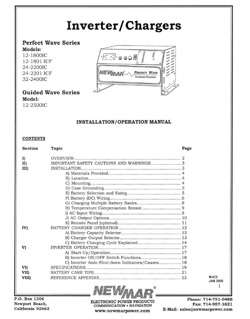
NewMar 12-1800IC User manual

NewMar
NewMar PT-14W User manual

NewMar
NewMar SOL 20 User manual

NewMar
NewMar PT-24-20W User manual

NewMar
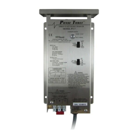
NewMar Phase Three PT-7 User manual

NewMar
NewMar PHASE THREE PT-14 User manual

NewMar
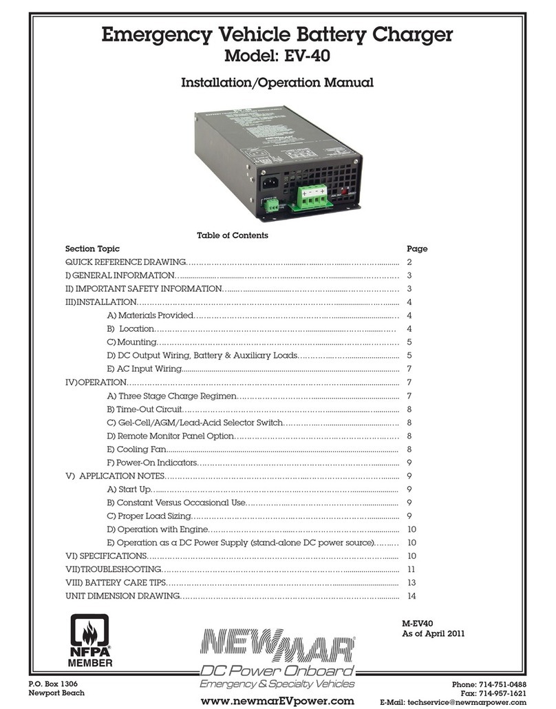
NewMar EV-40 User manual

NewMar
NewMar Phase Three PT-70a User manual

NewMar
NewMar Guided Wave 12-1200IC User manual

NewMar
NewMar PT-24-20U User manual