U.S.A. HEADQUARTERS
P.O. Box 1306, Newport Beach, CA 92663
Phone: 714-751-0488 Fax: 714-957-1621
EURO WAREHOUSE
Phone:+31-35-603-2494
Fax:+31-35-603-2149
www.newmarpower.com
ELECTRONIC POWER PRODUCTS
COMMUNICATION !!
!!
!NAVIGATION
5
4. Study all battery manufacturer’s specific precautions such as removing or not removing
cell caps while charging and recommended rates of charge.
GROUNDING AND a.c. POWER CORD CONNECTION
1. The charger should be grounded to reduce the risk of electric shock.
(For marine applications only) EXTERNAL CONNECTIONS TO THE CHARGER SHALL
COMPLY WITH UL RECOMMENDATIONS AND/OR UNITED STATES COAST GUARD
ELECTRICAL REGULATIONS (33CFR183, SUB-PART I)
(For marine applications only) THE INSTALLATION AND PROTECTION OF VESSEL
WIRING ASSOCIATED WITH BATTERY CHARGERS SHALL COMPLY WITH ABYC STAN-
DARDS; E-8) AC ELECTRICAL SYSTEMS ON BOATS, E-9) DC ELECTRICAL SYSTEMS ON
BOATS, AND A-20) BATTERY CHARGING DEVICES.
III) INSTALLATION
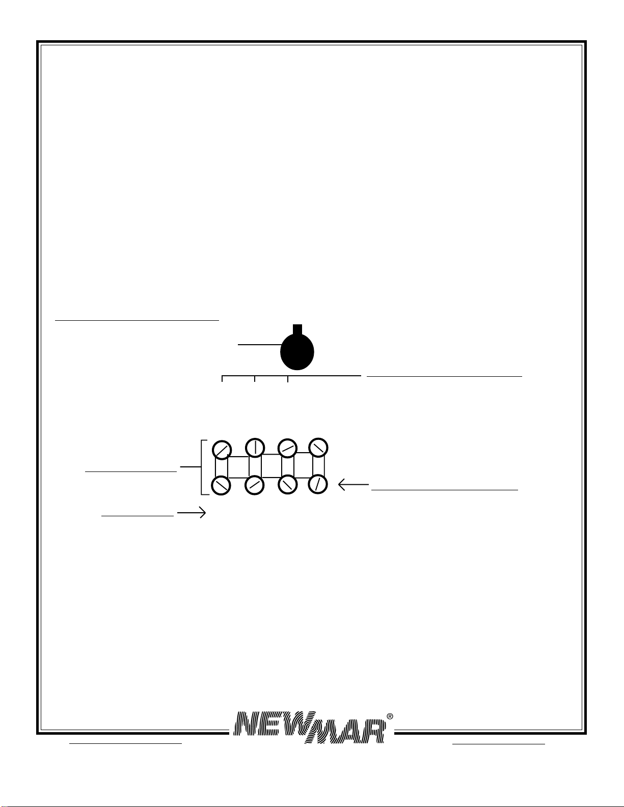
A) Materials Provided
The Phase Three charger is provided completely assembled and ready for installation. The
installer must provide four suitable 1/4" mounting screws/washers, as well as d.c. output
wiring and connectors. Proper sizes and gauges for the wire and connectors are noted in
section D following. A warranty registration/customer satisfaction card has been included in
the packaging. Upon completion of the installation, please fill out this card and return it to
the factory. You will be contacted promptly if you have any problems with or questions
about your Phase Three charger.
B) Location
The charger should be mounted on a wall, bulkhead or other suitable mounting surface as
close to the batteries to be charged as possible. Do not mount the charger directly over the
batteries as battery fumes may cause excessive corrosion. WARNING: The charger is not
ignition protected so it must not be located in an area where ignition protected equip-
ment is required. The area should be well ventilated and free from excessive moisture,
exhaust manifolds and battery fumes.
Vertical mounting is preferred. However, horizontal mounting is acceptable where absolutely
necessary. Do not mount the charger where water, spray or condensation can occur, as this
will shorten charger life. It should not be located where there is a possibility of dust or debris
being drawn into the unit through the fan. A minimum of 2" clearance around the charger is
recommended for proper cooling.
If the charger is located in an extreme heat area, such as an unventilated engine room, and
maximum operating temperature is exceeded, an automatic thermal protection circuit will
reduce power output by half or in extreme overheating may even turn the charger completely
off. Thermal cycling will shorten the life of the charger, so if this condition occurs repeatedly,