Newtec 3 00 Series User manual

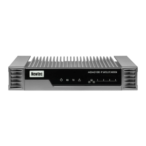
Newtec 3X00 Modem
Setup and Reference Guide
Revision R11.9.0
Documentation of the interface between the Newtec 3X00 modem/router and
the AvL Technologies AAQ antenna controller, reference information, and
troubleshooting guide
Appendix Ab
AvL Technologies
900-159-027

Newtec 3X00 Modem Guide
1
Revision History
Date
Revision
Revision
By
Approved
By
Revision Description
12/8/16
R11.8.0
SW
MF
Initial Release
2/13/17
R11.9.0
WL/AY
JF
Updates for 11.9.0, added figures for
device setup, updated config items
Contents
1. Introduction ........................................................................................................................................................................ 2
2. Setup Guide......................................................................................................................................................................... 3
Hardware....................................................................................................................................................................... 32.1.
Software ........................................................................................................................................................................ 52.2.
Hardware Connection ................................................................................................................................................... 52.3.
2.3.1. Serial Communication Connection .......................................................................................................................... 5
2.3.2. Ethernet Communication Connection ..................................................................................................................... 5
2.3.3. Newtec Communication .......................................................................................................................................... 7
3. Configuration ...................................................................................................................................................................... 8
Core Configuration Items .............................................................................................................................................. 83.1.
Target Configuration Items ........................................................................................................................................... 93.1.
Signal Configuration Items ............................................................................................................................................ 93.2.
Feed Configuration Items .............................................................................................................................................. 93.3.
4. Operation .......................................................................................................................................................................... 10
Functional Overview.................................................................................................................................................... 104.1.
Sensor Outputs............................................................................................................................................................ 104.2.

Newtec 3X00 Modem Guide
2
Module Windows ........................................................................................................................................................ 114.3.
4.3.1. Device Window...................................................................................................................................................... 11
4.3.2. Device Control Window ......................................................................................................................................... 12
5. Issues and Troubleshooting .............................................................................................................................................. 12
Figures
Figure 1 - Front Panel.............................................................................................................................................................. 3
Figure 2 –Back Panel .............................................................................................................................................................. 4
Figure 3 - Version Info............................................................................................................................................................. 5
Figure 4 –Ethernet Setup ....................................................................................................................................................... 6
Figure 5 - Advance Network Settings...................................................................................................................................... 6
Figure 6 - Newtec Antenna Controlling Tab............................................................................................................................ 7
Figure 7 - Configuration Core.................................................................................................................................................. 8
Figure 8 - Target Profile........................................................................................................................................................... 9
Figure 9 - Command Window ............................................................................................................................................... 10
Figure 10 –Sensor Output .................................................................................................................................................... 10
Figure 11 –Device Window .................................................................................................................................................. 11
1. Introduction
The Newtec modem has receive and transmit capabilities allowing for satellite communication. The Newtec Modem
Module supports any Newtec modem with the 3X00 designation (where X is any number). The Newtec modem can be
integrated into the AvL AAQ system to provide accurate beam pointing, and Internet and communications services. This
document describes the concepts required to use the Newtec modem as part of the AvL AAQ antenna system.
Newtec 3X00 Modem Guide
3
2. Setup Guide
Hardware2.1.
The hardware needed for the system includes:
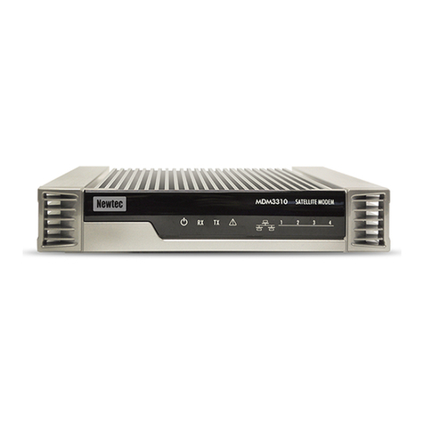
Newtec 3X00 Modem (pictured below)
AvL AAQ Controller.
Figure 1 - Front Panel
Number
Item
Description
1
Power LED
Blue continuous –when powered up.
2
RX Indicator LED
Blue continuous –forward satellite signaling receiving.
3
TX Indicator LED
Blue blinking –traffic transmitting via the satellite link.
4
Warning LED
Yellow continuous –when the terminal is not logged on to
the satellite network.
5
LAN indicator LEDs
Blue continuous –Link layer status.
Blue blinking –Ethernet frames are received or
transmitted

Newtec 3X00 Modem Guide
4
Figure 2 –Back Panel
Number
Item
Description
1
24 V power cable connector
Power connector.
2
TX connector
Indoor connection for the transmit coax cable.
3
Earth Connection
Used when the modem is installed within a rack to
ensure that all equipment chassis fixed within a rack are
at the same technical earth potential.
4
RX connector
Indoor connection for the receive coax cable.
5
Fan connector
Connection for the optional fan kit. For future use –not
yet supported.
6
Gigabit Ethernet cable
connectors
Connection for the LAN, type RJ-45 (Ethernet cable).
•Left LED (orange continuous): Link layer status.
•Right LED (orange blinking): Ethernet frames are
received or transmitted.
7
Reset button
Multi-functional button:
•Press once briefly (hold less than 5 seconds) to reboot
the modem.
•Press and hold for more than 5 seconds to perform a
Factory Reset. This will reboot the modem and change
all IP-settings back to the default factory settings.
8
USB Port
For future use –not yet supported.

Newtec 3X00 Modem Guide
5
Software2.2.
Be sure that the Remote Client, ROM, and device module are at or above the versions shown below:
Path
Main Window → Help → Version Info.
Level 0
Figure 3 - Version Info
Hardware Connection2.3.
2.3.1. Serial Communication Connection
A serial connection is not an option for the hardware associated with this module.
2.3.2. Ethernet Communication Connection
When setting the system to communicate by Ethernet, it is important to make sure the controller has a network path
to the Newtec modem so the modem can query the controller over the network. The example shown in the
following figures represents a typical installation.

Newtec 3X00 Modem Guide
6
Figure 4 –Ethernet Setup
Path
Main Window → File → SettingsAAQ Network Interface Options
Level 1
The modem has a static IP Address that allows for communication. The AAQ controller must be configured to be on
the same network as the modem. Additionally, the Customer Network 2 IP address of the AAQ controller (Figure 5)
must match the ACU IPv4 address that is set in the Newtec Web GUI (Figure 6).
Figure 5 - Advance Network Settings

Newtec 3X00 Modem Guide
7
2.3.3. Newtec Communication
1. Change your computer’s TCP/IPv4 IP address to be on the same network as the modem’s default IP address.
The default IP address for the modem is normally 192.168.1.1 so your computer’s TCP/IPv4 IP address must
be set to 192.168.1.XXX (for example 192.168.1.200).
2. In the AAQ GUI open the Advanced Network Settings dialogue box by selecting File->Settings and select the
AAQ Network Interface Options button. (Figure 5) Enter an IP address in the Customer Network 2 box that is
on the same network as the modem’s default IP address. In this example an IP address of 192.168.1.5 is
chosen.
3. Access the Newtec’s Web GUI (Figure 6) by typing its IP address into a web browser. (i.e. 192.168.1.1)
4. Go to the Antenna Controlling tab.
5. Change the ACU IPv4 Address to match the AAQ’s Customer Network 2 IP address. (i.e. 192.168.1.5)
6. Change the ACU TCP Port to the same value as the “Newtec Module Open AMIP Port” (Figure 7) from AAQ
Core Configuration. (i.e. 5001)
Figure 6 - Newtec Antenna Controlling Tab

Newtec 3X00 Modem Guide
8
3. Configuration
Core Configuration Items3.1.
1. Access the AAQ Remote GUI and login to the AAQ.
2. Go to View Configuration under core tab and search for “Newtec”
3. Change the “Newtec Module Open AMIP Port” to the desired value (or leave as default: 5001)
Path
Main Window → View Configuration Core
Level 4
Figure 7 - Configuration Core
Long Name
Level
Type
Value
Range
Description
Newtec Module
Open AMIP Port
4
Integer
0 -
65535
The port to use when connecting to the
Newtec Module (default: 5001)
Newtec Com Port
4
String
-
This config item is not used for this module.
Newtec Com Port
Settings
4
Integer
-
This config item is not used for this module.
Newtec Gradient
Sample Time
4
Integer
0-300
Sample time in seconds for detecting signal
gradient (default: 2)
Newtec Noise Sample
Time
4
Integer
0-60000
Sample time in MS for detecting signal noise
(default: 1000)

Newtec 3X00 Modem Guide
9
Target Configuration Items3.1.
Path
Main Window → View Configuration Target
Level
Figure 8 - Target Profile
Note: Acquisition Sources are changed to Newtec
Note: Target Selection is paired properly with Profile Name
Item
Level
Type
Value
Range
Description
Scan Source
1
Choice
-
Signal source used when acquiring on a satellite
Coarse Source
1
Choice
-
Source used for coarse peaking on a signal.
Fine Source
1
Choice
-
Source used for fine peaking on a signal.
Signal Configuration Items3.2.
There are no additional Signal Configuration Items for this module.
Feed Configuration Items3.3.
There are no additional Feed Configuration Items for this module.

Newtec 3X00 Modem Guide
10
4. Operation
Functional Overview4.1.
Once the profile is setup, run the Acquire command and the antenna will move to find the target satellite while using
the Newtec as a signal source.
Figure 9 - Command Window
If configured to use a reference satellite, the antenna will acquire the reference satellite first in order to update the
heading. Once the heading is updated, the antenna will move directly to the target satellite and perform coarse and
fine peaking.
If not configured to use a reference satellite, the antenna will go to the elevation of the target satellite and perform an
azimuth raster scan looking for a modem lock. The antenna will then use the EsNo to coarse and fine peak on the
target satellite.
Once the target has been found, the modem will automatically be commanded to begin transmitting. The modem’s
lock and transmit status may be monitored through the Device Window.
Sensor Outputs4.2.
Path
Main Window → View→ Sensor Output
Level 0
Check the boxes beside any Sensor Outputs you wish to view for monitoring operations.
Figure 10 –Sensor Output

Newtec 3X00 Modem Guide
11
The table below describes the Sensor Outputs relevant to this module
Item
Description
Newtec Detected Noise
A measure of unwanted signal power used for calculating the
actul received signal level
Newtec Min Lock Signal
An automatically generated sensor output not used in this
Module
Newtec Min Valid Signal
An automatically generated sensor output not used in this
Module
Newtec Rx. Lock
Flag that indicates whether Newtec unit has declared carrier lock.
Newtec Rx. Sig.
Signal level value as read from Newtec modem.
Newtec Signal Average
Readout of average signal as read from AAQ
Newtec Signal Gradient
Mathematical approximation of signal change over time in
coordination with “Newtec Gradient Sample Time” configuration
item as read from AAQ.
Module Windows4.3.
4.3.1. Device Window
The software provides a Device Window for use in monitoring operation. To check that configuration has been
completed successfully, on the AAQ Remote GUI, go to View Device Window and ensure that the Connection
Status reads “Connected”. Once configured properly, the modem should connect to the AAQ in less than a minute.
If this time is exceeded, double check all configuration items and physical connections.
Path
Main Window → View→ Device Window
Level 0
Figure 11 –Device Window

Newtec 3X00 Modem Guide
12
Item
Description
Connection Status
Indicates whether the Newtec device is connected or not
Signal Strength
Indicates the relative strength of the signal received
Lock Status
Indicates whether the Newtec device has carrier lock or not
Transmit Status
Indicates whether the Newtec transmitter is enabled or not
EsNo
Indicates the “Energy per symbol vs noise” of the locked carrier
4.3.2. Device Control Window
A Device Control Window is not needed for monitoring operation and is not included in the software.
5. Issues and Troubleshooting
Issue
Description
Corrective Action
Newtec modem does not
communicate
Device Window not
populated or shows the
Connection Status as
“Not Connected”
(Device Window is found
under: Main Window →
View →Device Window)
Insure that correct AAQ remote, ROM
and Module versions are loaded. (See
Figure 3–Version Info)
Check that IP addresses are connected
to the same network. (Review Sections
2.3.2 and 2.3.3 of this manual)
Check that the modem has power.
Check all Ethernet cables and
connections.
Check that the NewTec is configured as
the Scan, Coarse, and Fine Source for
the current Target profile
Newtec does not lock onto
desired satellite.
Antenna fails to return a
received lock Rx signal.
And/or
Error message “Invalid signal
for peaking”
And/or
Error message “All Signal
Sources tried With No Valid
Signal Detected”
Check all RF cables and connections.
Check that the system has a valid
Heading, Longitude, and Latitude.
Check that the modem has the correct
options file or is configured for the
current Target.
Check all Scan and Peaking parameters
in the Signal tab of the Configuration
Window (see the AAQ Users Manual for
more information.)
This manual suits for next models
1
Table of contents
Other Newtec Modem manuals

Newtec
Newtec MDM2200 User manual

Newtec
Newtec iNetVu MDM3X00 User manual

Newtec
Newtec MDM9000 User manual

Newtec
Newtec TP210 User manual

Newtec
Newtec EL470 User manual

Newtec
Newtec MDM2210 User manual

Newtec
Newtec AZ420 User manual

Newtec
Newtec MDM6000 User manual

Newtec
Newtec EL170 User manual

Newtec
Newtec AZ430 User manual