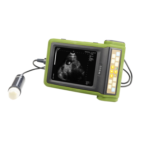
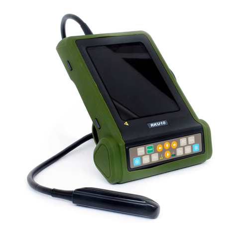
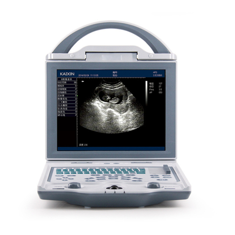
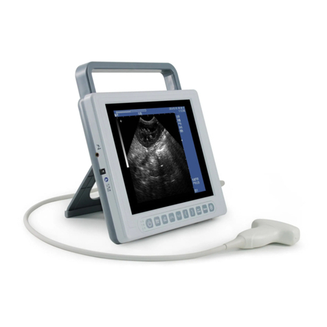
Kaixin KX5600L User manual

KAIXIN
KX5600L
Full Digital Ultrasonic Diagnostic
Instruments (Vet)
User’s Manual
Xuzhou Kaixin Electronic Instrument Co., Ltd.

i
Contents
Introduction ........................................................................................................................................................ I
Statement ............................................................................................................................................................ I
Warranty and Repair Service..............................................................................................................................I
Manufacturer’s Information................................................................................................................................I
Chapter 1 Product Specifications.................................................................................................................1
1.1 Power Supply................................................................................................................................................1
1.2 Operating Environment ................................................................................................................................1
1.3 Storage and Transportation...........................................................................................................................1
1.4 Dimensions and Weight................................................................................................................................1
Chapter 2 System Configuration..................................................................................................................2
2.1 Standard Configuration.................................................................................................................................2
2.2 Optional Parts...............................................................................................................................................2
Chapter 3 Product Introduction...................................................................................................................3
3.1 Structure Composition of the Instrument......................................................................................................3
3.2 Components Name........................................................................................................................................3
3.3 Parts of the Probe..........................................................................................................................................3
3.4 Function Keys Description...........................................................................................................................3
3.5 Symbols Description.....................................................................................................................................4
Chapter 4 Installation and Check................................................................................................................6
4.1 System Installation........................................................................................................................................6
4.2 Ultrasonic Probe Installation ........................................................................................................................6
4.3 Shutter Release Installation ..........................................................................................................................7
4.4 Video Recorder Installation ..........................................................................................................................8
4.5 Working Power.............................................................................................................................................8
4.6 Ultrasonic Probe Check Before and After Operation....................................................................................8
4.7 Main Unit Check Before and After Operation..............................................................................................8
4.8 System Reset.................................................................................................................................................9
Chapter 5 Functional Operation................................................................................................................10
5.1 Startup and Shutdown.................................................................................................................................10
5.2 Screen Display Reverse..............................................................................................................................10
5.3 System Functions Setting ...........................................................................................................................10
5.4 Mode Selection...........................................................................................................................................12
5.5 Image Adjustment and Control...................................................................................................................14
5.6 Gain adjustment in A mode.........................................................................................................................16
5.7 Auto Ruler (Automatic Backfat Measure)..................................................................................................16
5.8 Restore Parameters .....................................................................................................................................17
5.9 Body Mark and Probe Mark .......................................................................................................................17
5.10 One-key Storage Image ............................................................................................................................17
5.11 Image Management...................................................................................................................................18
5.12 Cine Loop .................................................................................................................................................19
5.13 Text Input..................................................................................................................................................19
5.14 Check List Management...........................................................................................................................20
Chapter 6 Measurement..............................................................................................................................21
6.1 General Measurement.................................................................................................................................21
6.2 Obstetric Measurement...............................................................................................................................23
6.3 Backfat thickness and Lean percentage measurement................................................................................24
Chapter 7 System Maintenance..................................................................................................................26
ii
7.1 Daily Maintenance......................................................................................................................................26
7.2 Use and Maintenance for the Rechargeable Lithium Ion Battery Pack......................................................27
7.3 Replaceable Parts........................................................................................................................................28
7.4 Troubleshooting..........................................................................................................................................29

I
Introduction
Thank you for purchasing KX5600L Full Digital Ultrasonic Diagnostic Instruments (Vet).
Users shall carefully read through this user's manual and fully understand the text before operating
the product.
Please keep this user's manual after reading so that you can access at any time when needed.
The user’s manual issue date: May 24, 2023, Version: V1.00
For the changes of appearance, this user's manual is subject to change without further notice!
Statement
Kaixin was considered responsible for the safety, reliability and performance in case of meeting all
the following requirements: all repairs are performed by professionals recognized by Kaixin; all
replacement parts and accessories, consumables involved repairs are Kaixin Company.
Warranty and Repair Service
Purchased the product warranty, sees the company's service policies.
Manufacturer’s Information
Xuzhou Kaixin Electronic Instrument Co., Ltd.
Kaixin Mansion, C-01, Economic Development Zone, Xuzhou, Jiangsu, China.
Zip Code: 221004
Tel: +86-516-87732932 87733758
Fax: +86-516-87732932 87792848
Website: http://www.kxele.com

1
Chapter 1 Product Specifications
1.1 Power Supply
Adapter ratings: 100-240V~, 50Hz/60Hz 1A max
Output of adapter: DC12.8V 3.5A
Main device rating: DC12.8V 3.5A
Internal supply voltage: DC10.89V-12.6V
1.2 Operating Environment
Ambient temperature: 10℃~40℃
Relative humidity: 30%~75% (without condensation)
Atmospheric pressure: 700hPa~1060hPa
1.3 Storage and Transportation
1.3.1 Storage and Transportation Conditions
Ambient temperature: -20℃~55℃
Relative humidity: 30%~93% (without condensation)
Atmospheric pressure: 700hPa~1060hPa
1.3.2 Storage and Transportation
1. If the instrument is stored over 3 months, take out the instrument from the packing case, connect
it to power supply for 4 hours, and then disconnect the power and place it in the case again
following the direction indicated by arrows on the package. Store the case in the warehouse. Do
not pile the case. The instrument case should have adequate space from ground, walls and ceiling
of the warehouse.
2. Environment requirement
Ambient temperature: -20℃-55℃; Relative humidity: 30%-93% (without condensation);
Atmospheric pressure: 700hPa-1060hPa. The warehouse should be well ventilated and free of
direct sunlight and corrosive gas.
3. Shockproof measures have been taken inside the packing case to allow for transport by air,
railway, land and sea. The goods shall not be exposed to poor weather conditions like rain and
snow, nor shall the goods be placed upside down, bumped, knocked or over-stacked.
1.4 Dimensions and Weight
1. Main unit dimension: approx. 285 * 143 * 35mm3(L * W * T)
2. Main unit net weight: 1.1kg (excluding accessories)

2
Chapter 2 System Configuration
2.1 Standard Configuration
1.
Main unit
1 unit
2.
3.5 MHz convex array probe
1 PC
3.
Power adapter
1 PC
4.
Power cable
1 PC
5.
Strap
1 PC
6.
Leather bag
1 PC
7.
Plastic sealed box
1 PC
8.
Shutter release
1 PC
9.
Hood
1 PC
2.2 Optional Parts
1.
4.0 MHz convex array transrectal probe
2.
Video recorder
3.
Leather case (including strap)
4.
Probe holder

3
Chapter 3 Product Introduction
3.1 Structure Composition of the Instrument
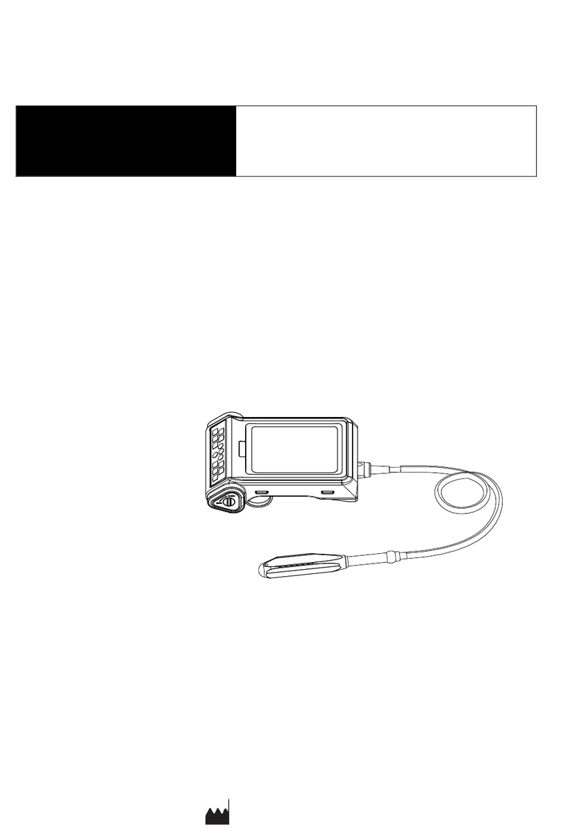
KX5600L Full Digital Ultrasonic Diagnostic Instruments (Vet) are composed of main unit, probe and
power adapter etc.
3.2 Components Name
3.3 Parts of the Probe
Take 3.5MHz convex array probe for example:
Figure: Parts name of 3.5MHz convex array probe
Name
Function
(1) Acoustic lens
To convert electric signal to ultrasonic signal based on principle of
converse piezoelectric effect. The ultrasonic signal, after entering the
human body, is reflected as echo wave and converted to electric signal
again. The acoustic lens is on the probe surface. Supply ultrasonic
coupling gel to the acoustic lens surface when performing ultrasonic
diagnosis.
(2) Cable
To connect the probe to the probe connector.
(3) Probe connector
To connect the probe to ultrasonic diagnostic instrument.
3.4 Function Keys Description
SN.
Function keys
Function
1
1. In real-time status, select mode;

4
2. In frozen status, text input, exchange the starting point
and end point of the measurement, etc.
2
1. Main-menu;
2. In frozen status, save image/read image/cine loop.
3
Enter Confirm
4
Freeze/Unfreeze the image;
Hold down freeze key for some time to achieve screen
display up/down reverse.
5
One-key storage image
6
Adjust the imaging depth
7
Direction Keys
8
Quit various states
9
Power switch
3.5 Symbols Description
This instrument uses the symbols listed in the following table, and their descriptions are explained.
Symbols
Description
Type B applied part
Indicates the need for the user to consult the instructions
for use for important cautionary information.
Follow instructions for use
Power switch
Power supply indication
Battery charge indication
Direct current
Polarity of direct current power connector
Manufacturer
Date of manufacture
Serial number

5
Up
Keep dry
Fragile
Stacking limit by number
Temperature limits (Storage and transport)
Humidity limitation (Storage and transport)
Atmospheric pressure limitation (Storage and transport)
Marking for the separate collection of electrical and
electronic equipment

6
Chapter 4 Installation and Check
4.1 System Installation
Please carefully read through and fully understand the use-method before installing the equipment,
and check the goods for its completeness.
You can hold the equipment handle to use or be hung on the chest to use.
The equipment is hung on the chest to use:
a. Take out the instrument and accessory, first put the equipment into the leather bag;
b. Stick the Velcro of leather bag to the handle of the main unit, and then install the strap on the
rings of the leather bag;
c. Adjust the length of the strap, and hang it on the neck for use;
d. When using outdoors, if the outdoor light is strong, install the hood on the main unit.
Adjustable length strap
Hang on the neck
4.2 Ultrasonic Probe Installation
4.2.1 Ultrasonic Probe Connection
Warning: Before connecting or using the probe, make sure that the probe,
connecting cable and connector are in normal condition (free of cracks or drop). Use
of defective probe may cause electric shock.
Attention:
1. Turn off the ultrasonic system before disconnecting the probe. Disconnecting the
probe with system power on may damage the system or probe.
2. Before disconnecting the probe, place the cable and probe on a stable and leveled
position so that the probe may not be damaged or injury person by unexpected fall.
3. Probe is highly sensitive to shake, be used with caution. About probe’s use and
cleaning, the details see the relevant sections.
Warning: Do not use the probe not provided by our company, otherwise the
equipment and the probe will cause damage, and may cause fire in extreme cases.
Warning:Heat sinks on the upper and lower sides of main unit to allow heat release.
When main unit is working, the temperature of heat sink may be high. If used, be
careful not to touch the heat sink, so as not to burn!

7
1. Turn off the system, pinch the oval position on both sides of the probe cable
while keep the arrow above, as shown ;
2. As shown below, insert the probe connector horizontally into the probe socket labeled
"PROBE" of the main unit, when inserting the probe, the notch on the probe connector should
be aligned with the position of the red dot mark on the main unit housing, and push the probe
firmly into the probe socket of main unit;
3. After pushed in place, hold the machine with one hand and rotate the ring clockwise with one
hand until the probe is locked.
Note: Lock the ring clockwise in the direction indicated on the label. Before turning the
ring clockwise, be sure to push the probe connector into place and then rotate to
prevent the ring from idling.
Probe connection schematic
4.2.2 Ultrasonic Probe Disconnection
1. Turn off the system, pinch the oval position on both sides of the probe cable with one hand
and rotate the probe ring counterclockwise with the other hand;
2. When rotating counterclockwise, pull out the ultrasonic probe connector vertically when the
ring touches the probe cable.
Probe disconnection schematic
4.3 Shutter Release Installation
Install shutter release to Freeze interface (TV/VGA interface) as shown in the figure.

8
4.4 Video Recorder Installation
1. Turn off the system, connect the equipotential terminal ( ) of the video recorder to the
earthing;
2. Connect one end of the video connection line to the video recorder and the other end to the
“TV/VGA interface”of the main unit;
3. Insert one end of power plug (jack) of the video recorder to the power input socket of the
video recorder, the other end to the power supply socket.
Note: When connecting the video recorder, the main unit needs to output the TV signal.
Please contact Kaixin Company.
4.5 Working Power
The instrument can work when it is connected to the external power supply or the battery capacity
is sufficient.
4.5.1 Connect to External Power Supply
1. Connect to the power adapter
Insert the output plug of adapter into power input interface of the main unit.
2. Connect to the main power supply
Insert the power plug (jack) furnished with the machine into power input socket of the power
adapter, the other end to the mains socket-outlet. The instrument uses three-core power supply. It
connects with the protective earth line when power plug inserts into its socket.
4.5.2 Powered by Battery
When connected to the external power supply, the instrument is powered by the external power
supply. When disconnected from the external power supply, the instrument is powered by the
battery.
4.6 Ultrasonic Probe Check Before and After Operation
Before and after ultrasonic diagnosis to check if there are any exceptionally on the surface of the
probe or cable jacket, such as peeling, cracks, bulge, or if the acoustic lens is reliable, disinfected or
cleaned.
4.7 Main Unit Check Before and After Operation
4.7.1 Inspection Before Start-up
Check the following items before starting the machine:
1. The temperature, humidity and atmospheric pressure shall meet the requirements of operation
condition.
2. No condensation occurs.
3. No distortion, damage or contamination on system and peripheral. Clean the parts as specified
in relevant sections, if the contaminant is present.
4. Check the control panel, display screen and enclosure to ensure they are in good working
condition and free of abnormity (such as cracks and loosened screws).
5. No damage on power cable, and hard up on its connection.

9
6. Check probe and its connections to ensure they are free of abnormity (such as scuffing,
drop-off or contamination). If the contaminant is present, clean the contaminated objects as
specified in relevant sections.
7. Check all the ports of the machine for possible damage or blockage.
4.7.2 Inspection After Start-up
Check the following items after starting the machine:
1. No abnormal voice, strange smell and overheating appear.
2. Check the machine to ensure a normal start-up: The power supply indicator is on and startup
picture is shown on the screen. Then the machine will be automatically set in B mode.
3. Check the acoustic lens for abnormal heat when the probe is in use. This can be done by hand
touching the probe to feel the temperature of the lens.
4. Check the image to ensure trouble-free display (no excessive noise or flicker).
5. Check the control panel to ensure normal operation condition.
6. Check the instrument to ensure that the phenomenon of local high temperature will not appear.
4.8 System Reset
In case of abnormal screen display or no-working for system operation, try to restart the system by
turning on/off the main unit power.

10
Chapter 5 Functional Operation
5.1 Startup and Shutdown
In shutdown status, press key, machine starts up, power indicator lights.
In startup status, hold down key, machine shuts down, power indicator goes out. Please
note that when shut down the machine, the time of pressing key is a rather long than normal
pressing key.
5.2 Screen Display Reverse
Hold down freeze key for some time to achieve the screen display reverse, to meet left/right
hand use.
5.3 System Functions Setting
5.3.1 Time Setting
1. Press key to enter main-menu, press direction keys to move cursor to “Setup”;
2. Press key to enter setting interface;
3. Press direction keys to move the symbol “<”to point to “Year, Month, Day, Hour and
Min”;
4. When setting year, month, day, hour and minute, press direction key to increase value or
press direction key to decrease value;
5. Press key to confirm the time setting and quit setting interface.
5.3.2 TV Mode Setting
1. Press key to enter main-menu, press direction keys to move cursor to “Setup”;
2. Press key to enter setting interface;
3. Press direction keys to move the symbol “<” to point to “TV Mode”;
4. Press direction keys to achieve TV mode conversion between PAL and NTSC;
5. Press key to confirm the setting and quit setting interface.
5.3.3 Energy Saving Setting
1. Press key to enter main-menu, press direction keys to move cursor to “Setup”;
2. Press key to enter setting interface;
3. Press direction keys to move the symbol “<” to point to “Sleep”;
4. Press direction keys to select energy saving time among 01~99 minutes or select
“Off”;
5. Press key to confirm the setting and quit setting interface.

11
Note: Go beyond the system setting sleep time without pressing any key, the machine will
automatically enter the energy saving status. Press any key, the system will return to
normal operation status.
5.3.4 Characters Brightness Setting
1. Press key to enter main-menu, press direction keys to move cursor to “Setup”;
2. Press key to enter setting interface;
3. Press direction keys to move the symbol “<” to point to “Font Bright”;
4. Press direction keys to select characters brightness among 160, 192, 224 and 255;
5. Press key to confirm the setting and quit setting interface.
5.3.5 Hospital Name Setting
1. Press key to enter main-menu, press direction keys to move cursor to “Setup”;
2. Press key to enter setting interface;
3. Press direction keys to move the symbol “<” to point to “Hospital”;
4. Press key, the cursor is located above “ID”; at the same time characters input menu will
be shown at the bottom of the screen:
Caps 0 1 2 3 4 A B C D E F G H I J K L M
Shift 5 6 7 8 9 N O P Q R S T U V W X Y Z
Press direction keys to move cursor to point to Caps, and then press key to achieve
capital and small letter conversion; If the cursor point to Shift, press key to achieve the
conversion between the letter and punctuation;
5. Press direction keys to choose “numbers” or “characters” and press key to confirm;
6. If need modify the content, in the characters input status press Shift key, the special characters
input menu is shown at the bottom of the screen displays:
Press direction keys to move cursor to point to character “ ” or “ ”, press key, move
the cursor to the position need to deleted character, and then press direction keys to move
cursor to character “ ”, press key, delete input content and retype.
7. Press key to quit the character input status and save this setting.
5.3.6 Key Sound Setting
1. Press key to enter main-menu, press direction keys to move cursor to “Setup”;
2. Press key to enter setting interface;
3. Press direction keys to move the symbol “<” to point to “KeySound”;
4. Press direction keys to select between “On” and “Off”;
5. Press key to confirm the setting and quit setting interface.

12
5.3.7 Grid Setting
1. Press key to enter main-menu, press direction keys to move cursor to “Setup”;
2. Press key to enter setting interface;
3. Press direction keys to move the symbol “<” to point to “Grid Set”;
4. Press direction keys to select “00”-“08”;
“00”shows “no grid”,
“01”shows “line grid”,
“02”shows “dot grid”,
“03”shows 10mm spacing dot-like scale,
“04”shows 2mm spacing dot-like scale,
“05”show 10mm spacing and 2mm spacing dot-like scales,
“06”shows longitudinal 1mm spacing grid (Depending on the probe, the grid is only
displayed when the image depth is less than a certain value),
“07”shows longitudinal 5mm spacing grid,
“08”shows longitudinal 10mm spacing grid;
5. Press key to confirm the setting and quit setting interface.
Note: Grid is displayed on B mode after has been set.
5.3.8 WIFI Switch Setting
1. Press key to enter main-menu, press direction keys to move cursor to “Setup”;
2. Press key to enter setting interface;
3. Press direction keys to move the symbol “<” to point to “WIFI SWITCH”;
4. Press direction keys to select between “On” and “Off”;
5. Press key to confirm the setting and quit setting interface.
Note: The WIFI function is to be upgraded.
5.3.9 Mode Setting
1. Press key to enter main-menu, press direction keys to move cursor to “Setup”;
2. Press key to enter setting interface;
3. Press key to enter mode selection menu;
4. Press direction keys to move the symbol “<” to point to the checkbox for “Mode 4B”,
“Mode BM”or “Mode M”;
5. Press key to uncheck, press key again to check;
6. Press key to confirm the setting and quit setting interface.
Note: After the mode is unchecked, the image of the related mode is no longer displayed.
5.4 Mode Selection
In real-time mode, press key repeatedly to switch modes among B, B/B, 4B, B/M, M and A.

13
Note: 4B, B/M, and M mode are checked by default in the checkbox.
5.4.1 B Mode
B mode is a basic operation mode after startup and a single-framed B mode image is displayed.
Press key to freeze/unfreeze the image. In real-time mode, press key to exit B mode.
5.4.2 B/B Mode
1. In real-time mode, press keyto enter B/B mode.
2. B/B image switch. Press key to enter main-menu, press direction keys to move
the cursor to “BB Mode” and then press direction keys to switch image display; the
selected image is activated and the other one is frozen.
3. In real-time mode, press key to exit B/B mode.
5.4.3 4B Mode
1. In real-time mode, press keyto enter 4B mode.
2. 4B image switch. Press key to enter main-menu, press direction keys to move the
cursor to “4B Mode”, then press direction keys to switch display among four images;
the selected image is activated and the other three are frozen.
3. In real-time mode, press key to exit 4B mode.
5.4.4 B/M Mode
1. In real-time mode, press keyto enter B/M mode.
2. Change M scan mode. Press key to enter main-menu, press direction keys to move
cursor to “M Mode” and then press direction keys to change the M scan mode.
3. Move sample line. Press key to quit the current using status for direction keys. Press
direction keys to move sample line.
4. In real-time mode, press key to exit B/M mode.
5.4.5 M Mode
1. In real-time mode, press keyto enter M mode.
2. Change M scan mode: Press key to enter main-menu, press direction keys to move
cursor to “M Mode” and then press direction keys to change the M scan mode.
3. Change M scan speed: Press key to enter main-menu, press direction keys to move
cursor to “M Speed” and then press direction keys to select the eight kinds of scan speed.
4. In real-time mode, press keyto exit M mode.

14
5.4.6 A Mode
In real-time mode, press key to enter or exit A mode.
5.5 Image Adjustment and Control
5.5.1 Image Brightness and Contrast Adjustment
The user should adjust the brightness and contrast of the image according to the actual conditions of
the environment.
1. In the startup default real-time status, press key to quit the current using status of
direction keys;
2. Press direction keys , the “SBRIGH, SCONTR”adjustment bars appear on the screen;
3. Press direction keys , move the cursor to “SBRIGH, SCONTR”;
4. Press direction key to increase brightness and contrast, press direction key to
decrease them;
5. Finish the adjustment, press key or automatically later exit the adjustment status.
Note: When adjusting the brightness and contrast, if you cannot adjust by pressing the
direction keys , you must exit the current use state of the direction keys.
5.5.2 Total Gain Adjustment
In real-time mode, press key to enter main-menu, press direction keys to move cursor
to “Gain” in the display area. Press direction key to increase image total gain and direction key
to reduce total gain so as to control the total gain of the entire image.
5.5.3 Near Field Gain Adjustment
In real-time mode, press key to enter main-menu, press direction keys to move cursor
to “Near” in the display area. Press direction key to increase near field gain and direction key
to reduce near field gain so as to control the gain in near field region.
5.5.4 Far Field Gain Adjustment
In real-time mode, press key to enter main-menu, press direction keys to move cursor
to “Far” in the display area. Press direction key to increase far field gain and direction key
to reduce far field gain so as to control the gain in far field region.
5.5.5 Dynamic Range Adjustment
In real-time mode, press key to enter main-menu, press direction keys to move cursor
to “Dyn” in the display area. Press direction key to increase the value of dynamic range and
direction key to decrease the value of dynamic range so as to control the dynamic range of the
entire image.

15
5.5.6 Depth Range Selection
In real-time mode, press key to enter main-menu, press direction keys to move cursor to
“Depth” in the display area and then press direction keys to select eight kinds of depth.
Or, in real-time mode, repeatedly press key to select eight kinds of depth.
5.5.7 Frequency Adjustment (Frequency conversion)
In real-time mode, press key to enter main-menu, press direction keys to move cursor
to “Freq” in the display area. Press direction keysto achieve frequency conversion.
5.5.8 Frame Correlation Adjustment
In real-time B, B/B, 4B or B/M mode, press key to enter main-menu, press direction keys
to move cursor to “FrameAvg” in the display area. Press direction keys to achieve
four levels of frame correlation.
5.5.9 Image Post-process Adjustment
In real-time mode, press key to enter main-menu, press direction keys to move cursor
to “IP” in the display area and then press direction keys to obtain four levels of corrected
images.
5.5.10 Edge Enhancement Adjustment
In real-time mode, press key to enter main-menu, press direction keys to move cursor
to “IE” in the display area and then press direction keys to gain four levels of sharpened
images.
5.5.11 Local Zoom and Local Additive Color
In real time mode, press key to enter main-menu, press direction keys to move cursor
to “LocalZoom” in the display area, press key, a box appears. Press direction keys to move
the box to the position to be enlarged, the selected image will be enlarged; Press key to quit
local zoom status.
In the color display, the selected image which by above mentioned operation will be enlarged and
added color.
5.5.12 Image Left/Right Reverse
In real-time B, B/B, 4B or B/M mode, press key to enter main-menu, press direction keys
to move cursor to “L/R” in the display area and then press direction keys to select
“L” or “R”to achieve image left/right reverse. The image is flipped left/right, that is, the probe
scanning direction is changed. The probe scanning direction is indicated by the arrow on the upper
left area of the image.

16
5.5.13 Image Up/Down Reverse
In real-time mode, press key to enter main-menu, press direction keys to move cursor
to “UPDOWN” in the display area and then press direction keys to select “U” or “D”to
achieve image up/down reverse.
5.5.14 Color Selection
In real-time mode, press key to enter main-menu, press direction keys to move cursor
to “Color” in the display area and then press direction keys to achieve the conversion of
eight kinds of colors (including one kind of black and white).
5.5.15 Image Filter
In real-time B mode, press key to enter main-menu, press direction keys to move
cursor to “Filter” in the display area and then press direction keys to achieve the conversion
of two kinds of filter.
5.5.16 Focus Position Adjustment
In real-time mode, press key to quit main-menu status, press direction keys to move
the focus up and down.
5.5.17 Image Freeze/Unfreeze
In real-time mode, press key to freeze the image; in frozen status, press key to unfreeze
the image.
5.6 Gain adjustment in A mode
In real-time A mode, press key to enter main-menu, press direction keys to move
cursor to “Gain” in the display area. Press direction key to increase image gain, press direction
key to reduce it.
5.7 Auto Ruler (Automatic Backfat Measure)
1. In real-time B mode, press key to enter main-menu, press direction keys to move
cursor to “AutoRuler” in the display area and then press direction keys to select “0”
or “1”to turn off or turn on the automatic backfat measure. “0”means: turn off the automatic
backfat measure; “1”means: turn on the automatic backfat measure.
2. Press key, freeze the desired image, a vertical dotted line of fat thickness measurement
appears in the middle of screen, the backfat measurement value is automatically displayed at
the “+:----mm” on the right side of the screen.
3. Press direction keys to select “Clear”in display area and press key to clear all
marks and data.
Table of contents
Other Kaixin Diagnostic Equipment manuals

Kaixin
Kaixin DCU10 User manual

Kaixin
Kaixin DCU12 User manual

Kaixin
Kaixin MSU1 User manual

Kaixin
Kaixin MSU3 User manual

Kaixin
Kaixin RKU10 User manual

Kaixin
Kaixin DCU10 User manual

Kaixin
Kaixin KX5600F User manual

Kaixin
Kaixin MSU1Plus User manual

Kaixin
Kaixin KX5600 User manual

Kaixin
Kaixin K10 User manual