Nexo ID84 User manual

DP4988-01-DI
ID84 / ID84L
User manual
TABLE OF CONTENTS
Page 2/ 20 ID84
TABLE OF CONTENTS
TABLE OF CONTENTS___________________________________________________________________ 2
WARNINGS ____________________________________________________________________________ 3
EQUIPMENT ___________________________________________________________________________ 4
DESCRIPTION__________________________________________________________________________ 6
PRESET_______________________________________________________________________________ 7
CROSSOVER FREQUENCY______________________________________________________________ 10
ACCESSORIES ________________________________________________________________________ 11
ARRAY EQ____________________________________________________________________________ 13
MAINTENANCE________________________________________________________________________ 14
TECHNICAL SPECIFICATIONS ___________________________________________________________ 17
USER NOTES _________________________________________________________________________ 18
EU Conformity declaration
We,
NEXO SA
ZA DU PRE DE LA DAME JEANNE
60128 PLAILLY –France
Declare under our sole responsibility that the product
Type
Serial number
Loudspeaker
ID84 / ID84L
On the product
Is in conformity with the provisions of the following directive
including all applicable amendments:
2014/35/UE (Low Voltage Directive)
Applied rules and standards:
Plailly, 01 June, 2021
EN 13155, EN 62368
Joseph CARCOPINO, R&D Director
WARNINGS
ID84 Page 3/ 20
WARNINGS
PRECAUTIONS
-
repairable part.
If the system seems to be malfunctioning or damaged, stop using it at once and have it repaired by a NEXO qualified technician.
Do not expose the system directly to the sun or to the rain, do not immerse it into fluids, do not place objects filled with liquid on the
system. If a liquid gets into the system, please have it inspected by a NEXO qualified technician.
The connection should be performed by qualified technician, by ensuring that power is off.
Operating temperature with temperate climate: BR0°C to +40°C (+32°F to +104); -20°C à +60°C (-4°F to +140°F) for storage.
SAFETY INFORMATIONS
Read this manual before using the speaker.
Keep this manual available for further reference.
Observe all warnings and cautions.
Please check the NEXO Web site nexo-sa.com to get the most up-to-date version of this manual.
Ensure you are aware of the safety rules applying to rigging, stacking or installing on tripod or speaker stand. Failure to observe
these rules may expose persons to potential wounds or even death.
Only use the system with accessories specified by NEXO.
Please always consult a NEXO-accredited technician if the installation needs architectural works and observe following precautions:
Mounting Precautions:
- Please select screws and mounting location supporting 4 times the system weight.
- Do not expose the system to excessive dust, vibrations, to extreme cold or hot temperatures, to reduce the risk of
damaging components.
- Do not place the system in an unstable position: it could fall accidentally.
- ifications are adapted and that its height does not exceed
.
Connection and Powering Precautions:
- Unplug connected cables before moving the system.
- Power off the system before connecting the system.
- When switching on the installation, the amplifier must be powered last; when switching the installation off, shut off the
amplifier first.
- If you work by cold temperatures, progressively raise the level to nominal value during the first minutes of use, to allow the
system components to stabilize.
Please check regularly the system condition.
HIGH SOUND PRESSURE LEVELS
Exposure to very high sound pressure levels may cause permanent hearing losses. Degrees of hearing losses may be different
from one person to another, but almost everybody will be affected if exposed to high sound pressure levels during a long period of
time. The OSHA (Occupational Safety and Health Administration) American Agency specified the following maximal exposures:
Number of Hours
Sound Pressure Level (dBA),
Slow Response
8
90
6
92
4
95
3
97
2
100
1 ½
102
1
105
½
110
¼ or less
115
WASTE OF ELECTRIC OR ELECTRONIC EQUIPMENT
This symbol on the product or its packaging indicates that this product must not be treated as household waste.
Instead, it is your responsibility to hand it over to a designated collection point for the recycling of waste
electrical and electronic equipment. By ensuring your waste equipment is recycled, you will help prevent
potential negative consequences for the environment and human health, which could appear if this product was
not recycled. Recycling helps spare natural resources. For more information about the recycling of this product,
please contact your local city office, your household waste disposal service or your reseller.

EQUIPMENT
Page 4/ 20 ID84
EQUIPMENT
Locations for hanging on the back.
2 locations for connecting, 1 on the back and a quick connect in the base cover (ID84 only).
ID84 versions T & TIS: a directivity switch, located between the NL4 connectors, allows to virtually curve the
drivers to achieve 2 vertical directivity patterns:
•Narrow (0° / -10°)
•Broad (0° / -25°)
EQUIPMENT
ID84 Page 5/ 20
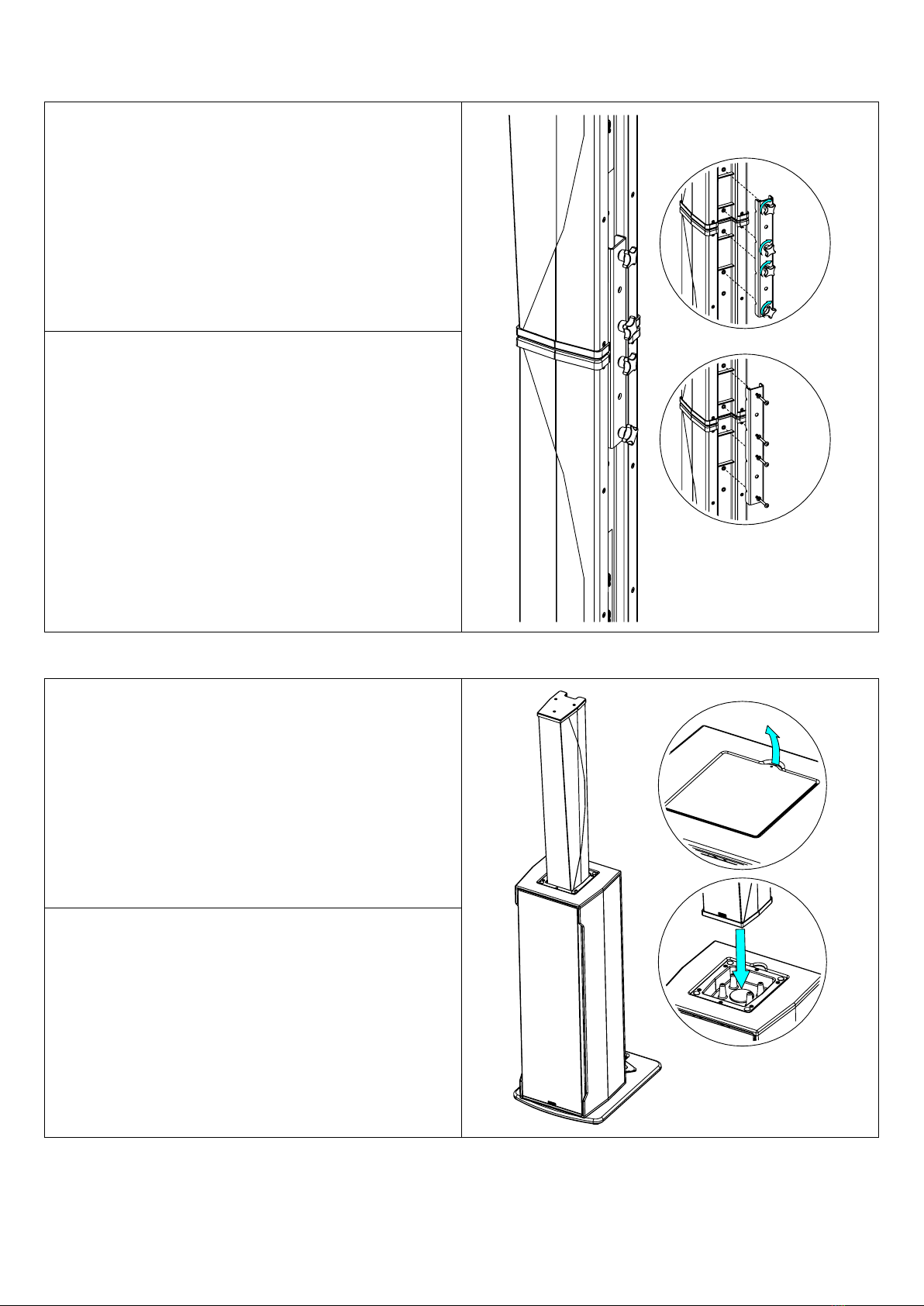
Assembly on ID84 / ID84L
Use IDU-COUPL to assemble 2x ID84.
Use only fasteners provided (thread lock coated screws for
permanent installation).
IMPORTANT
Use VNT-BP600 and IDT-BPADAPT for stacking.
Speaker must always be installed on a horizontal surface.
Stand height and footprint must be defined to prevent assembly
from collapsing.
Ensure that audience is not allowed within a safety area which
radius is equal or higher than assembly height.
Test steadiness of the assembly by pushing in all directions.
Assembly on IDS312
Open the trap above IDS312.
Place ID84 on IDS312, magnet keeps it in place
IMPORTANT
Speaker must always be installed on a horizontal surface.
Stand height and footprint must be defined to prevent assembly
from collapsing.
Ensure that audience is not allowed within a safety area which
radius is equal or higher than assembly height.
Test steadiness of the assembly by pushing in all directions.
DESCRIPTION
Page 6/ 20 ID84
DESCRIPTION
→ID84 is a column speaker, 2 ways passive
→ID84L is a column extension speaker, increase directivity control in LF
→Versions
•ID84 / ID84L: for Touring Application; black, white
•ID84-TIS / ID84L-TIS: for Touring Application, with Installation grille; black, white
•ID84-I / ID84L-I: for Permanent Installation; black, white
→ID84 Dispersion:
•Horizontal: 100°
•Vertical: +0°/-10° or +0°/-25°. Switch on the back
→ID84 can be used alone or with ID84L and/or IDS312 subwoofer
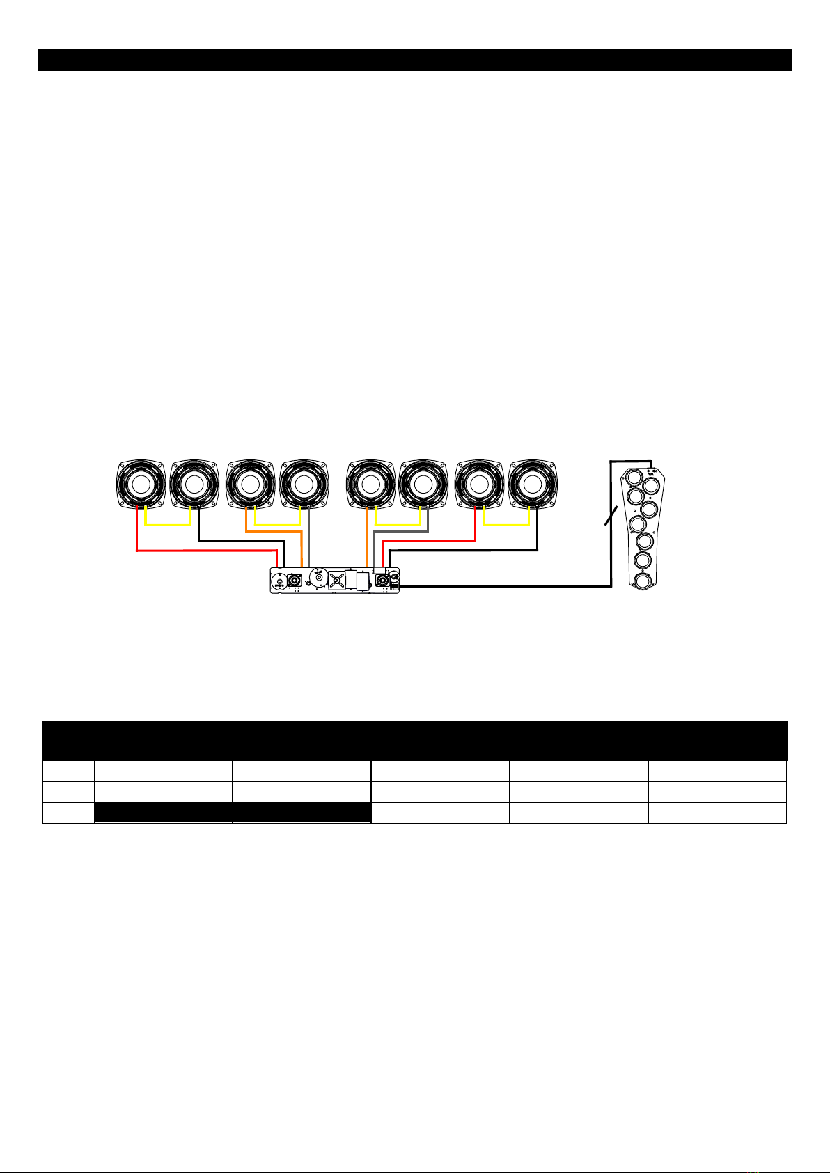
→ID84 / ID84-TIS / ID84L and ID84L-TIS are equipped with two NL4 connectors with parallel-wired pins. ID84 / ID84-TIS have
a quick connect in the base cover to be connected with IDS312 / IDS312-TIS.
ID84 / ID84-TIS use 2+/2-. The 1+/1- pins are used by the sub.
ID84L and ID84L-TIS use 1+/1-.
ID84-I and ID84L-I are equipped with a cable gland M16 (clamping range, Ø 5 to 12 mm), supplied with a fixed cable 2x 1.5
mm2section, length 2m, outside diameter 8mm ±1 mm
→Amplification
•ID84/ID84L speakers must be used with a NEXO processor to handle EQ, phase alignment, crossover and
excursion/thermal protection for the system loudspeaker.
•The following table shows the number of OD84, ID84L speakers and IDS312 subwoofers usable with each solution.
DTD +
DTDAMP4X0.7
DTD +
DTDAMP4X1.3
NXAMP4X1mk2
NXAMP4X2mk2
NXAMP4X4mk2
ID84
1 per chanel
1 per chanel
Up to 2 per chanel
Up to 2 per chanel
Up to 2 per chanel
ID84L
1 per chanel
1 per chanel
Up to 2 per chanel
Up to 2 per chanel
Up to 2 per chanel
IDS312
1 per chanel
1 per chanel
1 per chanel
PRESET
ID84 Page 7/ 20
PRESET
Please consult nexo-sa.com for NEXO TD Controllers firmware information.
For optimal acoustic performance, follow these rules:
•Always use at least 1x ID84.
•Never assemble more than 4 cabinets.
•Never use more than 2x ID84 or 2x ID84L in a column assembly.
•2xID84 can only be coupled upside-down for HF section continuity.
•Never link an ID84L to the top of an ID84.
For the ID84, the following setups are available:
→NARROW: directivity 0° / -10°.
→BROAD: directivity 0° / -25°.
Preset
•ID84 BROAD, with high pass at 90 or 120 Hz.
•ID84 NARROW, with high pass at 90 or 120 Hz.
For the ID84L, the following setups are available:
→NARROW: use when next to an ID84 in NARROW mode.
→BROAD: use when next to an ID84 in BROAD mode or when not directly attached to an ID84.
Preset
•ID84L BROAD, with high pass at 90 or 120 Hz.
•ID84L NARROW, with high pass at 90 or 120 Hz.
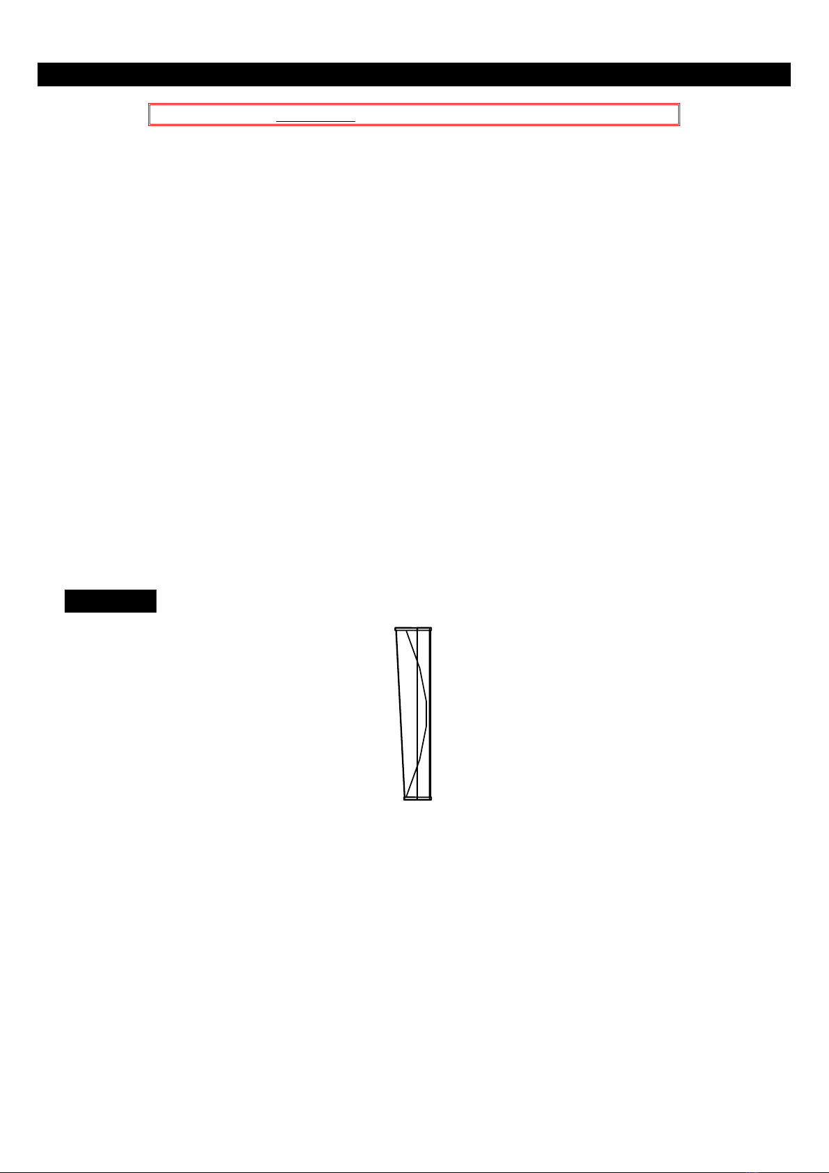
1x ID84
PRESET
Page 8/ 20 ID84
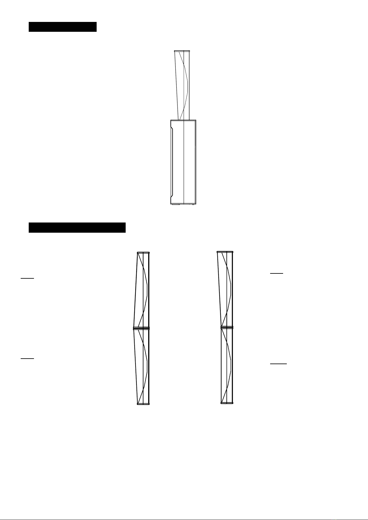
ID84 + IDS312
2xID84 / ID84 + ID84L
ID84
Switch and Set up:
NARROW or BROAD
ID84
ArrayEQ HF: +3dB
Switch and Set up:
NARROW or BROAD
ID84
Switch and Set up:
NARROW or BROAD
ID84L
Set up identical to ID84.

PRESET
ID84 Page 9/ 20
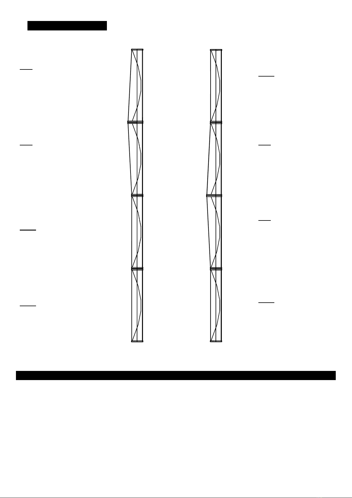
2xID84 + ID84L / 1x ID84 + 2xID84L
ID84
ArrayEQ HF: +1.5dB
Switch and Set up:
NARROW or BROAD
ID84
ArrayEQ HF: +4.5dB
Switch and Set up:
NARROW
ID84
ArrayEQ HF: +1.5dB
Switch and Set up :
NARROW or BROAD
ID84L
Setup NARROW
ID84L
Set up identical to the ID84
directly above.
ID84L
Setup BROAD
CROSSOVER FREQUENCY
Page 10 / 20 ID84
2xID84 + 2x ID84L
ID84
ArrayEQ HF: +3dB
Switch and Set up:
NARROW or BROAD
ID84L
Set up identical to the ID84
just below it.
ID84
ArrayEQ HF: +3dB
Switch and Set up:
NARROW
ID84
ArrayEQ HF: +3dB
Switch and Set up:
NARROW or BROAD
ID84L
Setup NARROW
ID84
ArrayEQ HF: +3dB
Switch and Set up:
NARROW or BROAD
ID84L
Setup BROAD
ID84L
Set up identical to the ID84
directly above.
CROSSOVER FREQUENCY
→90 Hz: Full range application.
→120 Hz: Use with a NEXO subwoofer, e.g. IDS312.

ACCESSORIES
ID84 Page 11 / 20
ACCESSORIES
WARNINGS
All ID84 / ID84L accessories are specifically rated in agreement with structural computations.
Never use other accessories –including push-pins –when assembling ID84 / ID84L cabinets than the ones provided by
NEXO: NEXO will decline responsibility over the entire ID84 accessory range if any component is purchased from different
supplier.
PROHIBITED: ID84/ID84L below ID84/ID84L or ID84/ID84L with IDS312 without dedicated accessory
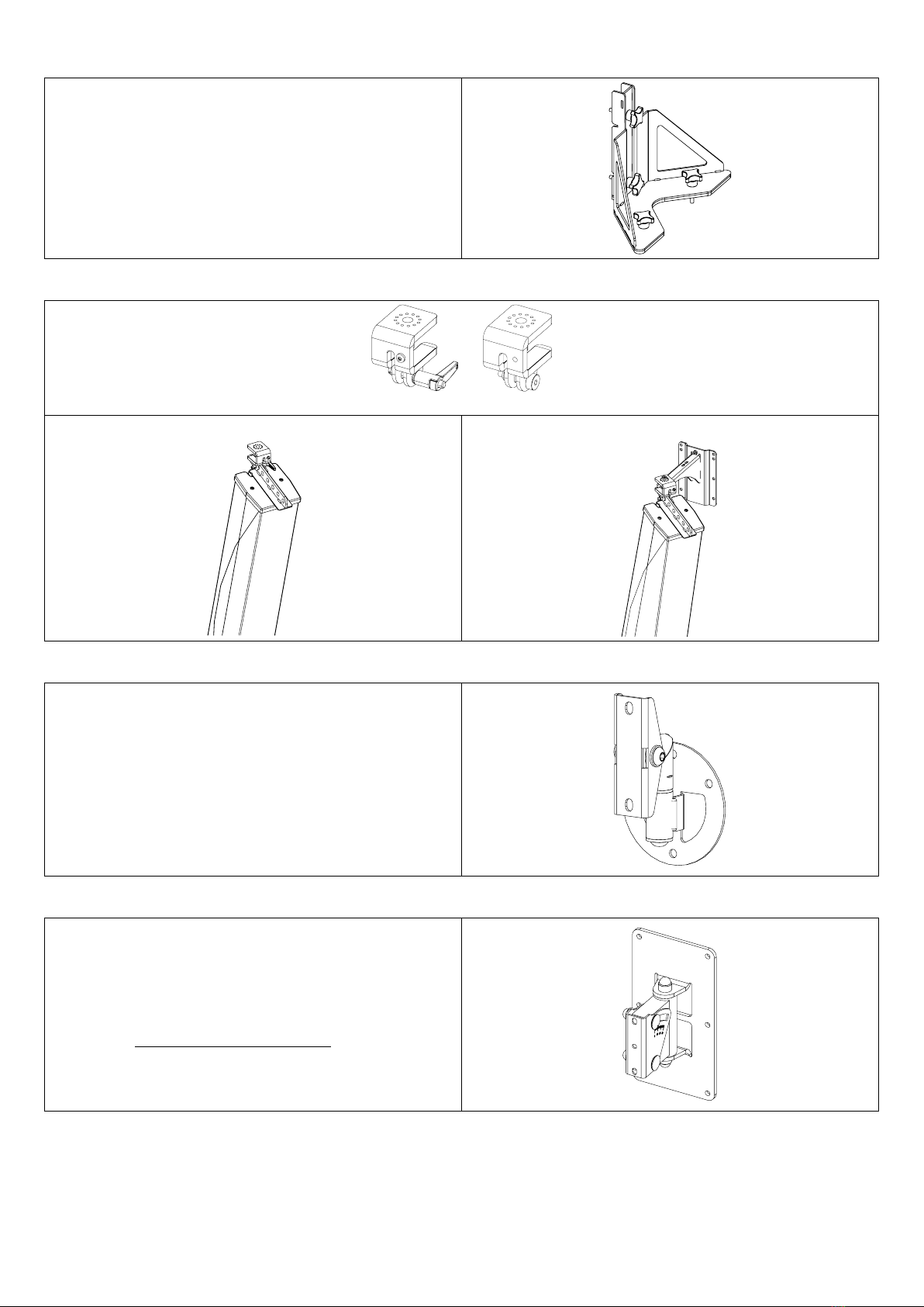
IDU-BUMP
Lifting bracket for ID84 / ID84L, can be used with VNT-
LIFTADAPT or VNI-WMADAPT and VNI-WM200.
Up to 2x ID84 + 2x ID84L can be lifted.
IDT-PLADAPT
Pole stand accessory for ID84 to be use with 35mm pole.
Can be fixed to upper part or lower part of the ID84.
For 1x ID84.
IDU-COUPL
Coupling bracket for ID84
Up to2x ID84 + 2x ID84L can be coupled together
IDU-TCBRK84
Truss-clamp bracket for ID84, to attach one or multiple ID84 to a
truss, in horizontal or vertical arrangement.
1x TCBRK84 for a maximum of 2x ID84
2x TCBRK84 and additional hanging on IDU-COUPL for a
maximum of 2x ID84L + 2xID84
VNT-BP600
Base plate for ID84/ID84L/IDS312, footprint M20 for extended
bar.
IDT-BPADAPT must be used to secure ID84/ID84L/IDS312 to
the base plate
•1x ID84L + 1x ID84
•1x IDS312 + 1x ID84
ACCESSORIES
Page 12 / 20 ID84
IDT-BPADAPT
Bracket for ID84/ID84L/IDS312, use to secure the assembly with
VNT-BP600
•1x ID84L + 1x ID84 (with IDU-COUPL).
•2x ID84 (with IDU-COUPL).
•1x IDS312 + 1x ID84 by using quick connect on
IDS312.
VNT-LIFTADAPT / VNI-WMADAPT
Max : 2xID84 + 2x ID84L
VNT-LIFTADAPT avec IDU-BUMP
VNI-WMADAPT avec IDU-BUMP & VNI-WM200
IDI-WB02 / VNI-WB02
Wall mount (up to 15 kg)
Use 2x WB02 to hang 1x ID84 on a wall.
± 35° horizontal
IDI-WM02 / VNI-WM02
Wall mount (up to 25 kg)
0° to -6° vertical and ± 50° horizontal
Can be fixed only on the upper hanging point of the ID84.
IDT-BAG84: transport bag for 1x ID84 ou ID84L
IDT-2CASE84: flight case for 2x (ID84 ou ID84L) + accessories (2x IDT-BUMP + 2x IDT-PLADAPT +
2x IDT-BPADAPT + 2x IDT-COUPL + little storage)
ARRAY EQ
ID84 Page 13 / 20
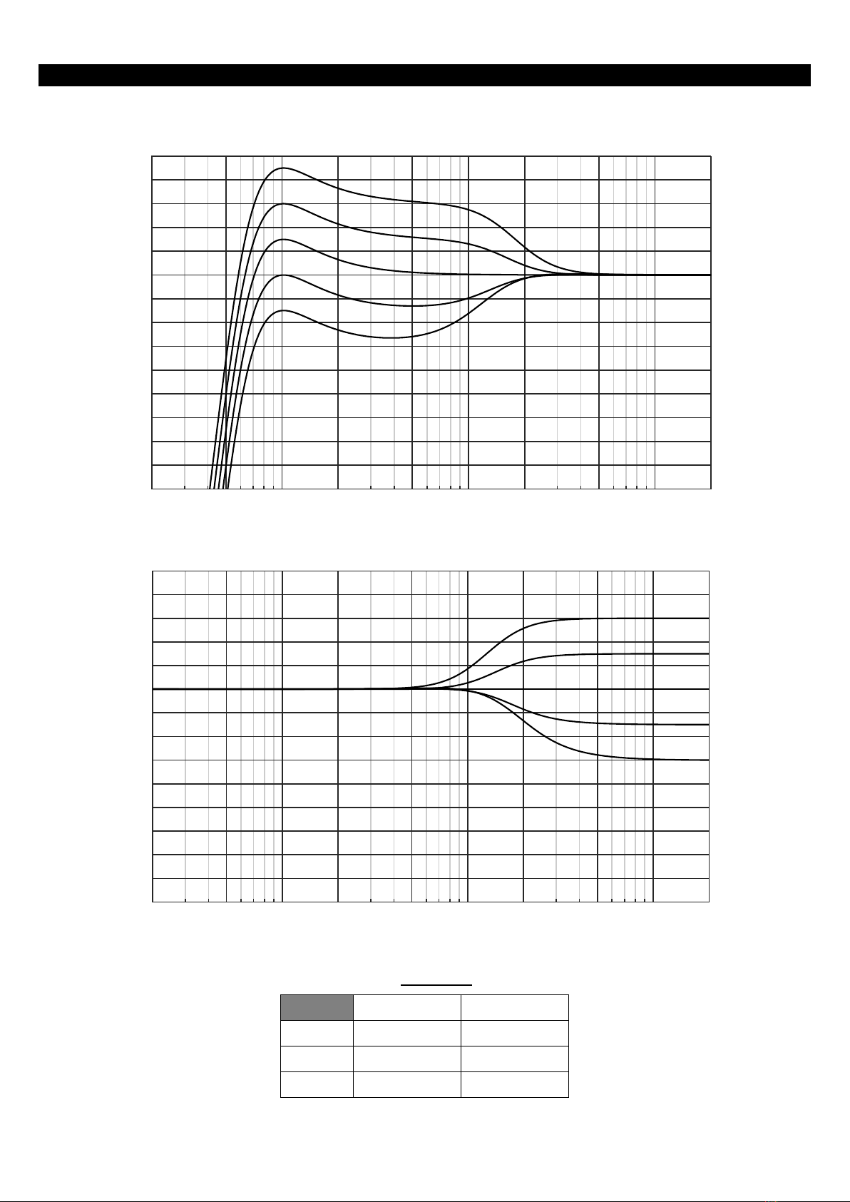
ARRAY EQ
The ArrayEQ allows to adjust the system frequency response in its lower range
(see curves below, with different ArrayEq values):
Apply the following array EQ HF on all ID84 (not ID84L) of the assembly:
1x ID84
2x ID84
0x ID84L
No adjustment
No adjustment
1x ID84L
+3dB
+1.5dB
2x ID84L
+4.5dB
+3dB
MAINTENANCE
Page 14 / 20 ID84
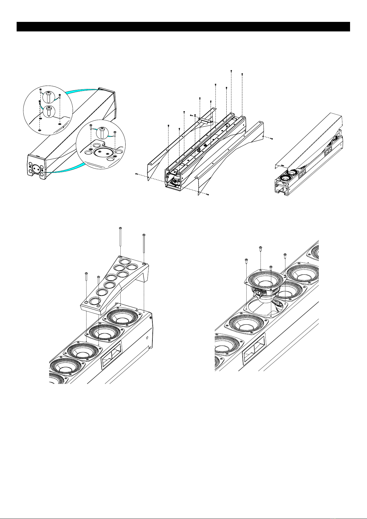
MAINTENANCE
Driver access
Remove the top cover (3 screws) and the
bottom cover (2 screws). Tx 15 –20
Tightening torque : 1.5Nm
Remove the 14 screws and the both sides plates. Tx 20. Tightening torque : 2.0Nm
Carefully, remove the grille.
Remove the 4 screws and the RJ45 connector.
Remove the HF assembly. Tx20
Tightening torque : 1.2Nm
Remove the 4 screws to access the 4-inch driver. Tx15
Tightening torque : 1.0Nm

MAINTENANCE
ID84 Page 15 / 20
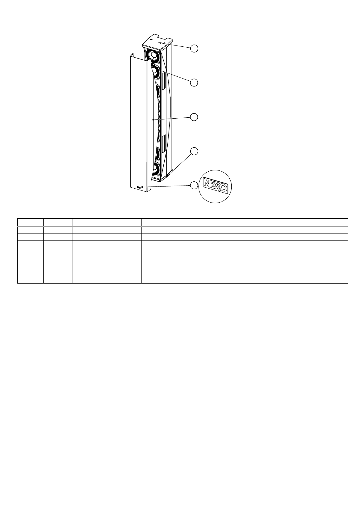
Spare parts
ID84
MARK
QUANTITY
REFERENCE
DESIGNATION
1
1
05ID84TOP
Top cover Black
1
05ID84TOP-PW
Top cover White
2
1
05ID84HFC
HF assembly complete Black
05ID84HFC-PW
HF assembly complete White
3
8
05HPB4-8
BASS DRIVER 4" 8 OHMS
4
1
05ID84T-A
Grille ID84 Touring Black
1
05ID84T-APW
Grille ID84 Touring White
1
05ID84I-A
Grille ID84-I Install Black
1
05ID84I-APW
Grille ID84-I Install White
5
1
05ID84QC
Quick connect Black
1
05ID84QC-PW
Quick connect White
6
1
05LOGNEXO3
Logo NEXO
7
1
05CAPSWTCH-2
Switch Cap Grey
MAINTENANCE
Page 16 / 20 ID84
ID84L
MARK
QUANTITY
REFERENCE
DESIGNATION
1
1
05ID84COV
Top cover Black
1
05ID84COV-PW
Top cover White
2
8
05HPB4-8
BASS DRIVER 4" 8 OHMS
3
1
05ID84LT-A
Grille ID84L Touring Black
1
05ID84LT-APW
Grille ID84L Touring White
1
05ID84LI-A
Grille ID84L-I Instal Black
1
05ID84LI-APW
Grille ID84L-I Instal White
4
1
05LOGNEXO3
Logo NEXO
TECHNICAL SPECIFICATIONS
ID84 Page 17 / 20
TECHNICAL SPECIFICATIONS
ID84 / ID84L WITH NEXO ELECTRONICS
Model
ID84
ID84L
Frequency range (±6dB)
90 Hz 20 kHz
90 Hz 1500 Hz
Peak SPL Level (1m)
135dB Peak
132dB Peak
Operating voltage
35Vrms (105Vpeak)
35Vrms (105Vpeak)
Vertical directivity
+0°/-10° or +0°/-25°
Depends on ID84 Main module
configuration and assembly
Horizontal directivity
100°
100°
Crossover Frequency
90Hz 120 Hz
90Hz 120 Hz
Nominal Impedance
4
4
SPECIFICATIONS
Model
ID84
ID84L
Components
LF: 8x 4; HF : 8x 1
LF: 8x 4
Material
Aluminum body and Magnelis® covers and grille
Finish
Black (RAL9005), white (RAL9016) powder coating or custom RAL
Front finish
Magnelis® front grille
Magnelis® front grille Automotive grade front cloth (versions I and TIS)
Fittings
Threated M6 inserts on the back
Connector
2x NL4, 4 poles connectors
Quick connect in the base cover
1x cable gland with 2x core cable
(version I)
2x NL4, 4 poles connectors
1x cable gland with 2x core cable
(version I)
Weight
15 kg / 33 lb
14 kg / 31 lb
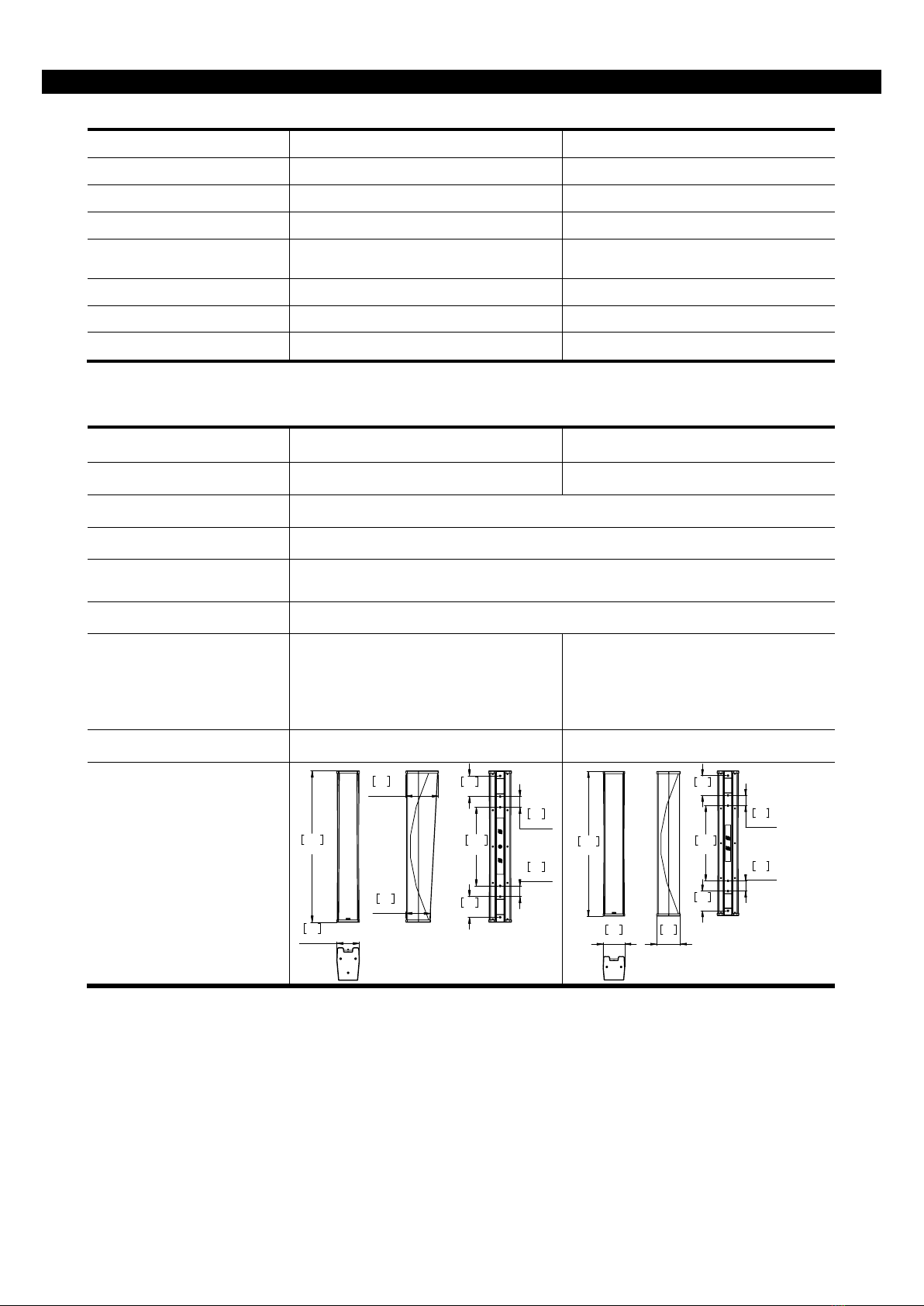
Dimensions

USER NOTES
Page 18 / 20 ID84
USER NOTES

USER NOTES
ID84 Page 19 / 20

This manual suits for next models
1
Table of contents
Other Nexo Speakers manuals


Nexo
Nexo P12 User manual

Nexo
Nexo ePS6-EN54 User manual

Nexo
Nexo ePS10 User manual

Nexo
Nexo P18 User manual

Nexo
Nexo P15 Under 2xL18 Rigging System User manual

Nexo
Nexo ePS6 User manual

Nexo
Nexo P12-TIS User manual

Nexo
Nexo ePS12-EN54 User manual

Nexo
Nexo MSUB12 Series User manual

Nexo
Nexo INSPACE DEFINITION ID24 Series User manual


