manuals.online logo
Brands
  1. Home
  2. •
  3. Brands
  4. •
  5. Nidek Medical
  6. •
  7. Medical Equipment
  8. •
  9. Nidek Medical Lex 1000 Guide

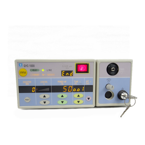
Nidek Medical Lex 1000 Guide

Installation-Adjustment
Manual
Rev. 11-18- 08
LEX 1000 Unpacking, Installation, Calibrations and Adjustments
I. Unpacking
a. Opening Carton.
b. Inspecting Unit & Accessories.
c. Bench Preparation. (See Diagram)
II.Installation
a. Unit Placement and Packing Material Removal.
b. Tank & Pump Hook Up.
c. Power Up, Software Verification, Upgrade procedure.
d. Inspection of Water Flow.
III.Calibrations and Adjustments
a. Calibration
1. LMU Feeler limit Calibration
2. LMU Calibration
3. ӨAxis Calibration Self-Diagnosis
4. Cover Calibration
b. Finish Size and Bevel Position Adjustment.
c. Axis Adjustment.
d. Feeler Axis Check and Adjustment (if necessary).
e. Polish Adjustment.
f. Groove (position and axis) Adjustment.
g. Safety Bevel (position and axis) Adjustment.
h. High Curve Adjustment.
i. Calibrate tracer with square jig (162.83 Circumf.+/- 0.05).
j. Set Clock Time and Date.
k. Final Check (w / Aviator Metal Frame) for fit, SFB and Polish.
1
Tank & Pump Hook Up
•Connect the Tank & Pump to the Main Body (see Diagram below)
2
•Screw Drain Hose into bottom Feed Hoses
of edger receiver grey quick
•Connect front hose to Pump 1 disconnect
•Connect rear hose to Pump 2 button
•Insert Pumps into lid cutouts
Drain Hose ---------
Drain Cuff-----------
Insert filter into
Tankandslip
over Tank receiver
Filter
•Fill Tank with cold water to a level that is approximately 1.5~2.0” from the top.
3
LEX-1000 Software Upgrade Procedure
Selectable Writing Mode
1. Check whether the file name of the extracted file is “LE13_XXX.MOT”.
2. Copy the “LE13_XXX.MOT” file to the USB jump drive (USB stick).
3. Power Off the unit. Open the access cover of the USB port. Insert stick.
4. Press and hold the Stop button while turning on the power switch. The
LEX-1000 starts the initialization and the USB stick check.
5. After checking the USB memory stick, the LEX-1000 LCD screen displays
the software versions that are found on the USB memory stick. Following
the instructions on the screen, you can scroll to select the desired version
and press [Enter]. A prompt will ask: “Yes [Enter]” or “No [Data Set].
Confirm that you have selected the proper software version and press
[Enter]. The LEX-1000 starts writing the software. During this process the
display shows a writing process bar and the following messages:
Version Up Mode
Now file loading
File Sum XXXX
“Don’t turn off the power switch”
6. When the progress bar is full, the software writing process is completed.
Screen will read :
Version Up Mode
Please Turn Off Power and Remove the USB Memory
7. Turn off the unit and pull out the USB memory stick. Close the access
cover to the USB port. Turn on the power and after the display shows the
layout screen once again, press the [Menu] key and verify that the
software has been upgraded.
END
4
LEX-1000 Adjustment Manual
11/18/2008 Santinelli International
Franco Aluigi
1.Before starting adjustment.
1.1 Confirming wheel configuration
Before starting adjustment, please check the wheel configuration.
PLB-G 13 + 12 + 17.5 + 17.5 + 17 = 77 PL-8 13 + 17 + 17.5 + 12 + 17 = 76.5
②③④⑤①
③④⑤②①
①Rough (Glass)
②Finish (Glass)
③Finish
④Polish
⑤Rough (Plastic)
①Rough (Glass)
④Polish
⑤Rough (Plastic)
③Finish
②Hi-Curve
PLB-8 17 + 17 + 17.5 + 17.5 = 69
①Rough
②Hi-curve
③Polish
④Finish
①②③④Rough (Glass): 2.45
Rough (CR39stic): 18.45
Finish (Glass Bevel): 31.45
Finish (CR39stic Bevel): 33.45
Finish (Flat): 48.95
Polish (Bevel): 50.95
Polish (Flat): 62.45
PL-8
Rough (Glass): 2.45
Hi- curve (Front): 17.39
Hi – curve (Rear): 26.95
Finish (Bevel): 36.45
Finish (Flat): 49.95
Polish: 61.95
Rough (CR39Plastic)
PLB-8
Rough: 60.87
Hi- curve (Front): 45.81
Hi – curve (Rear): 55.37
Finish (Bevel): 12.87
Finish (Flat): 14.87
Polish (Bevel): 30.37
Polish (Flat): 32.37
PLB-G
Wheel Parameter
5
1.2 Checking chuck pressure
Adjustment Parameter:
Press and hold (STOP), then press to go to Parameter screen. Select
Parameter setting, then press . Scroll page to Parameter setting (9/12 page)*
Chuck pressure (CR39/HPL): 100
Chuck pressure (PC/ACR/TRX/PUR): 100
Chuck pressure (GLS): 100
1. Call up a JOB. Any job is OK.
2. Set the chuck pressure JIG into the machine, then press , then (START).
3. When you press (START)a lens is chucked. Then press (STOP)to stop the
process. Measure chuck pressure. Proper chuck pressure is the following.
4. Chuck pressure (CR39/HPL): 45kg+/-5kg
Chuck pressure (PC/ACR/TRX/PUR): 45kg+/-5kg
Chuck pressure (GLS): 45kg+/-5kg
If not in tolerance, change parameter value to adjust chuck pressure.
2. Calibration and Adjustment
Adjustment Order
2-1Calibration
2-2 Finish Size and Bevel Position Adjustment
2-3 AXIS Adjustment
2-4 Feeler Axis Adjustment
2-5 Polish Adjustment
2-6 Groove Adjustment
2-7 Safety Bevel Adjustment
2-8 High Curve grinding Adjustment
To call up internal 45 circle : Press and hold then press
To call up internal 45 square : Press and hold then press FC SW.
* LEX1000 new software (V1.05 and later) has 16 menu pages. Menu pages 14~16 are LEX Drill parameters.
6
2.1 Calibration
Calibration Procedure
1. Press and hold (STOP), then press to go to Parameter screen. Select
Calibration, then press . The Calibration screen appears.
2. Remove cup holder, then install the calibration JIG.
3. Bring the cursor to the calibration that you would like to do, then press to start
4. SFB calibration
Calibration for SFB unit.
5. Full Calibration
Full calibration executes the following 4 calibration (5,6,7 and 8)
6. Bevel Calibration
Calibration for wheel position.
7. Wheel Calibration
Calibration for wheel axis
8. LMU Calibration
Calibration for LMU.
9. θAxis Self-Diagnosis.
This is to check θaxis movement to see if it is capable of soft mode.
10. Cover Calibration
Follow the instructions shown on the information bar. This calibration does not
require the JIG.
7
2.2 Finish Size and Bevel Position Adjustment
Here, in this adjustment we cut internal 45 circle and check finish size and bevel position.
For adjusting the finish size of CR39 plastic lens, -2D to -4D is recommended to be used.
Finish Size adjustment
Adjustment Parameter :
Press and hold (STOP), then press to go to Parameter screen. Select
Parameter setting, then press . Scroll the page to Finish Size (Page 1, 2/12)
CR39, Bvl : 0.00mm
CR39, Flt : 0.00mm
CR39, HCrv : 0.00mm
HPL, Bvl : 0.00mm
HPL, Flt : 0.00mm
HPL, HCrv : 0.00mm
PC/ACR, Bvl : 0.00mm
PC/ACR, Flt : 0.00mm
PC/ACR, HCrv : 0.00mm
TRX, Bvl : 0.00mm
TRX, Flt : 0.00mm
TRX, HCrv : 0.00mm
PUR, Bvl : 0.00mm
PUR, Flt : 0.00mm
PUR, HCrv : 0.00mm
GLS, Bvl : 0.00mm
8
GLS, Flt : 0.00mm
GLS, HCrv : 0.00mm
1. Call up internal 45 circle and grind lens in Bevel and Flat mode.
2. Measure the diameter of the lens (always at 180º line).
The tolerance for bevel is 45.00±0.05mm.
The tolerance for flat is 45.00±0.10mm.
Please adjust the size if it is out of tolerance. If you have 46.00m, please decrease
the value by 1.00. If you have 44.00mm, please increase the value by 1.00. Please
do finish size adjustment for each lens material.
Please note the size adjustment for high curve (HCrv). Please do this in section “2-8
High Curve Grinding Adjustment”.
Bevel Position Adjustment
Adjustment Parameter :
Press and hold (STOP), then press to go to Parameter screen. Select
Parameter setting, then press . Scroll the page to Parameter Setting (Page 9/12)
Bevel Position : 0.00mm
Bevel Position (GLS) : 0.00mm
1. Call up internal 45 circle and grind lens in Bevel “Guide” (5:5) mode. Thin lens
(plano) is recommended to be used.
2. Check the position of bevel to see if it comes to the center (5:5). If NOT, please
adjust it. Decreasing the value brings the bevel to the front. Increasing the value
brings the bevel to the rear. See the picture below.
3. If unit is PLB-G/PL-8, please adjust bevel position for glass using the same
procedure.
+ –
9
2.3 AXIS Adjustment
Here, in this adjustment we cut internal 45 square and check axis. For adjusting Axis of
CR39 plastic lens, -3D to –5D lens is recommended to be used.
Adjustment parameter :
Press and hold (STOP), then press to go to Parameter screen. Select
Parameter setting, then press . Scroll the page to Axis Adjustment (Page 6/12)
CR39/HCR39, Bvl :0.00
CR39/HCR39, Flt :0.00
PC/ACR/TRX/PUR, Bvl :0.00
PC/ACR/TRX/PUR, Flt :0.00
GLS, Bvl :0.00
GLS, Flt :0.00
Using Axis Alignment JIG to check cylinder axis
1. Call up internal 45 square and grind lens in Bevel and Flat mode.
2. After the machine completes the cycle, take the lens out and put it on the JIG to
check for axis.
3. If axis is shifted, please adjust it.
4. If tilted in CW direction, please decrease the value. If tilted in CCW direction please
increase the value. See the picture above (NOTE: this is viewed from the rear).
+
–
Scribing a line onto lens
1. Scribe a line onto lens, then block it. See the picture below.
2. Call up internal 45 square then grind lens.
3. After the machine finishes grinding, take the lens out, then put it on the graph paper.
4. Check axis. If tilted in CW direction, please decrease the value. If tilted in CCW
direction, please increase the value. See the picture below (NOTE: this is viewed
from the front).
10
–
+
Horizontal line
2.4 Feeler AXIS Adjustment
Adjustment Parameter:
Press and hold (STOP), then press to go to Parameter screen. Select
Parameter setting, then press . Scroll the page to AXIS Adjustment (Page 6/12)
Front feeler : 0.00
Rear feeler : 0.00
Using Axis Alignment JIG to check feeler axis
Rear feeler AXIS Adjustment
1. Use a Flat lens (No base curve). Apply grease to the rear surface of lens.
2. Call up internal 45 square.
3. Set a lens into the machine and set grinding condition Nylor Flat then hit START.
4. After measuring the rear side of lens please hit STOP.
5. Put a lens on the JIG and check the trace of rear side lens measuring.
6. If tilted in CW direction, please decrease the value. If tilted in CCW direction,
please increase the value. See the picture below (this is viewed from the rear).
+
–
Front feeler AXIS Adjustment
1. Use a Flat lens (No base curve). Apply grease to the front surface of lens.
2. Call up internal 45 square.
3. Set a lens into the machine and set grinding condition Nylor Flat then hit START.
4. After measuring the front side of lens please hit STOP.
5. Put a lens on the JIG and check the trace of front side lens measuring.
11
6. If tilted in CW direction, please increase the value. If tilted in CCW direction,
please decrease the value. See the picture below (this is viewed from the rear).
–
+
Cutting internal 45 square to check feeler axis
1. Please call up internal 45 square.
2. Bring the Size up to +3.00. Set grinding condition Nylor Flat.
3. Set a lens into the machine then hit START.
4. After the machine finish grinding, take the lens out then apply grease to the rear side
of the ground lens. Set the lens back to the machine and bring the size down to 0.00
then press START.
5. After measuring the rear side of lens please hit STOP.
6. Compare the trace of rear side lens measuring to the ground 45 square. If tilted in
CW direction, please decrease the value. If tilted in CCW direction, please increase
the value. See the picture below.
+ –
Rear
The trace of lens measuring
7. Use the same ground 45 square lens and apply grease to the front side of lens.
8. Set the lens into the machine then hit START.
9. After measuring the front side of lens please hit STOP.
10. Compare the trace of front side lens measuring to the ground 45 square. If tilted in
CW direction, please increase the value. If tilted in CCW direction, please decrease
the value. See the picture below.
Front
–+
The trace of lens measuring
12
2.5 Polish Adjustment
Polish Differential, PolishAXIS, Bevel Position (Pol)
Adjustment Parameter :
Press and hold (STOP), then press to go to Parameter screen. Select
Parameter setting, then press .Scroll the page to Polish Differential (Page 5/12)
CR39, Bvl :0.00mm
CR39, Flt :0.00mm
HPL, Bvl :0.00mm
HPL, Flt :0.00mm
PC/ACR/TRX, Bvl :0.00mm
PC/ACR/TRX,Flt :0.00mm
PUR, Bvl :0.00mm
PUR, Flt :0.00mm
1. Call up internal 45 square then grind lens in Bevel and Flat mode with polish.
2. Check Polish quality. If there is any unpolished area, please increase the polish
differential. If a lens edge gets burnt, please decrease the polish differential.
Normally the differential would be 0.1 to 0.2.
3. Check polish axis. If it is shifted (not polished evenly), please adjust polish axis. See
the picture below. If the left side is unpolished compared to the other side, please
increase the value. If the right side is unpolished compared to the other side, please
decrease the value.
Unpolished
If the left side is unpolished
compared to the other side
please increase the value.
4. For bevel polish, if you see only one side of bevel is polished, in this case please
adjust Bevel Position (Pol). If only front side is polished, please decrease the value.
If only rear side is polished, please increase the value.
13
Polish Size Adjustment
Adjustment Paremeter :
Press and hold (STOP), then press to go to Parameter screen. Select
Parameter setting, then press .Scroll the page to Polish Size (Page 4/12)
CR39, Bvl :0.00mm
CR39, Flt :0.00mm
HPL, Bvl :0.00mm
HPL, Flt :0.00mm
PC/ACR/TRX, Bvl :0.00mm
PC/ACR/TRX, Flt :0.00mm
PUR, Bvl :0.00mm
PUR,Flt :0.00mm
1. Call up internal 45 circle then grind lens in Bevel and Flat mode with polish.
2. Measure the diameter of polished lens (always at 180º line).
The tolerance for bevel is 45.00±0.05 ㎜.
The tolerance for flat is 45.00±0.10 ㎜.
Please adjust the size if it is out of tolerance. If you have 46.00m, please decrease
the value by 1.00. If you have 44.00mm, please increase the value by 1.00. Please
do finish polish size adjustment for each lens material.
14
2.6 Groove Adjustment
Groove Depth
Adjustment Parameter :
Press and hold (STOP), then press to go to Parameter screen. Select
Parameter setting, then press .Scroll the page to Parameter setting (Page 9/12)
Groove Depth : 0.00mm
1. Call up internal 45 circle. Use a CR39, -3D to -5D lens then grind lens in Nylor
Guide (Depth 0.0) mode.
2. The grooving wheel should barely touch the lens and you see a slight groove over
entire lens circumference. If too deep, please decrease the value. If no groove,
please increase the value.
Groove position
Adjustment Parameter :
Press and hold (STOP),then press to go to Parameter screen. Select
Parameter setting, then press .Scroll the page to Parameter setting (Page 9/12)
Groove Position : 0.00mm
1. Call up internal 45 circle. Use a CR39, -3D to -5D lens then grind it in Nylor Guide
(Position 5:5) mode.
2. Check the position of groove to see if it is in the center (5:5). If not, please adjust it.
Decreasing the value brings the groove to the front. Increasing the value brings the
groove to the rear. See the picture below.
+
-
+
-
15
Groove AXIS
Adjustment Parameter :
Press and hold (STOP), then press to go to Parameter screen. Select
Parameter setting, then press . Scroll the page to Axis Adjustment (Page 6/12)
CR39/HPL, Grv :0.00
PC/ACR/TRX/PUR, Grv :0.00
1. Call up internal 45 square. Use a CR39, -3D to -5D lens then grind it in Nylor Guide
(Depth 0.0) mode.
2. The grooving wheel barely touches the lens and you see a slight groove evenly over
entire lens circumference. View the front side of lens. If the right side is deeper,
please decrease the value. If the left side is deeper, please increase the value.
3. Also try a PC lens and check Groove Axis. It is the same procedure.
+ –
Front
Groove
16
2.7 Safety Bevel Adjustment
Before starting Safety Bevel Adjustment please set the parameters as shown below.
Front SFB size (Bevel) :0.3mm
Rear SFB size (Bevel) :0.3mm
Rear SFB size (Flat) :0.3mm
Also set the SFB mode (Bevel) to F & L
SFB mode (Bevel) :F & R
SFB Wheel Position (Bevel)
Adjustment Parameter :
Press and hold (STOP), then press to go to Parameter screen. Select
Parameter setting, then press . Scroll the page to SFB (Page 8/12)
SFB wheel position (Bvl, Fr):0.00mm
SFB wheel position (Bvl, Re):0.00mm
1. Call up internal 45 circle. Use a CR39, -3D to -5D lens then grind it in Bevel Guide
(5:5) with SFB.
2. Check amount of safety bevel on both the front and the rear side. The tolerance is
+/- 0.2mm. If the amount needs to be increased, please increase the value. If it
needs to be decreased, please decrease the value.
SFB Wheel Position (Flat)
Adjustment Parameter :
Press and hold (STOP), then press to go to Parameter screen. Select
Parameter setting, then press . Scroll the page to SFB (Page 8/12)
SFB wheel position (Flt, Fr):0.00mm
SFB wheel position (Flt, Re):0.00mm
17
1. Call up internal 45 circle. Use a CR39, -3D to -5D lens then grind it in Nylor Flat with
SFB mode.
2. Check amount of safety bevel on both the front and the rear side. The tolerance is
+/- 0.2mm. If the amount needs to be increased, please increase the value. If it
needs to be decreased, please decrease the value.
Safety Bevel AXIS (Bevel)
Adjustment Parameter :
Press and hold (STOP), then press to go to Parameter screen. Select
Parameter setting, then press . Scroll the page to SFB (Page 8/12)
Axis Adjustment (Bvl, Re) :0.00
Axis Adjustment (Bvl, Fr) :0.00
1. Call up internal 45 square. Use a CR39, -3D to -5D lens then grind it in Bevel Guide
(5:5) with SFB.
2. View the front side of lens and check axis of front safety bevel. If it tilted in CW
direction, please decrease the value. If tilted in CCW direction, please increase the
value. See the picture below.
Front
+ –
3. See the rear side of lens and check axis of rear safety bevel. If it tilted in CW
direction, please increase the value. IF tilted in CCW direction, please decrease the
value. See the picture below.
Rear
– +
18
Safety Bevel AXIS (Flat)
Adjustment Parameter :
Press and hold (STOP), then press to go to Parameter screen. Select
Parameter setting, then press . Scroll the page to SFB (Page 8/12)
Axis Adjustment (Flt, Re) :0.00
Axis Adjustment (Fltl, Fr) :0.00
1. Call up internal 45 square. Use a CR39, -3Dto-5D lens then grind it in Nylor Flat with
SFB mode.
2. Check axis of front safety bevel. If it tilted in CW direction, please decrease the value.
If tilted in CCW direction, please increase the value. See the picture below.
Front
+ –
3. Check axis of rear safety bevel. If it tilted in CW direction, please increase the value.
If tilted in CCW direction, please decrease the value. See the picture below.
– +
Rear

Other manuals for Lex 1000

1

Other Nidek Medical Medical Equipment manuals
Nidek Medical AR-360A User manual

Nidek Medical

Nidek Medical AR-360A User manual

Nidek Medical Nuvo Series User manual

Nidek Medical

Nidek Medical Nuvo Series User manual

Nidek Medical AFC-330 User manual

Nidek Medical

Nidek Medical AFC-330 User manual

Nidek Medical Mark 5 Plus User manual

Nidek Medical

Nidek Medical Mark 5 Plus User manual

Nidek Medical ARK-730A User manual

Nidek Medical

Nidek Medical ARK-730A User manual

Nidek Medical Mark 5 Nuvo Lite User manual

Nidek Medical

Nidek Medical Mark 5 Nuvo Lite User manual

Nidek Medical LT-980 User manual

Nidek Medical

Nidek Medical LT-980 User manual

Nidek Medical RT-3100 User manual

Nidek Medical

Nidek Medical RT-3100 User manual

Nidek Medical Ice 900 User manual

Nidek Medical

Nidek Medical Ice 900 User manual

Nidek Medical Mark 5 Nuvo MB User manual

Nidek Medical

Nidek Medical Mark 5 Nuvo MB User manual

Nidek Medical Magellan Mapper User manual

Nidek Medical

Nidek Medical Magellan Mapper User manual

Nidek Medical Mark 5 Nuvo Lite Series User manual

Nidek Medical

Nidek Medical Mark 5 Nuvo Lite Series User manual

Nidek Medical AR-600 User manual

Nidek Medical

Nidek Medical AR-600 User manual
Nidek Medical ARK-530A User manual

Nidek Medical

Nidek Medical ARK-530A User manual

Nidek Medical Nuvo8 User manual

Nidek Medical

Nidek Medical Nuvo8 User manual

Nidek Medical Mark5 Nuvo User manual

Nidek Medical

Nidek Medical Mark5 Nuvo User manual

Nidek Medical Mark 5 Nuvo Lite Family User manual

Nidek Medical

Nidek Medical Mark 5 Nuvo Lite Family User manual

Nidek Medical Nuvo 10 User manual

Nidek Medical

Nidek Medical Nuvo 10 User manual

Nidek Medical ARK-530 User manual

Nidek Medical

Nidek Medical ARK-530 User manual

Nidek Medical Mark 5 Nuvo Lite Series User manual

Nidek Medical

Nidek Medical Mark 5 Nuvo Lite Series User manual

Nidek Medical GYC-1000 User manual

Nidek Medical

Nidek Medical GYC-1000 User manual

Nidek Medical Nano User manual

Nidek Medical

Nidek Medical Nano User manual

Nidek Medical Mark 5 Nuvo Lite Family User manual

Nidek Medical

Nidek Medical Mark 5 Nuvo Lite Family User manual

Nidek Medical NT-510 User manual

Nidek Medical

Nidek Medical NT-510 User manual

Popular Medical Equipment manuals by other brands

Mortara ELI 150 Rx user manual

Mortara

Mortara ELI 150 Rx user manual

Boston Scientific RELIANCE 4-FRONT DF4-LLHH PHISICIAN'S LED MANUAL

Boston Scientific

Boston Scientific RELIANCE 4-FRONT DF4-LLHH PHISICIAN'S LED MANUAL

ISKO KOCH ISKOmed Rotadorm Care Service manual

ISKO KOCH

ISKO KOCH ISKOmed Rotadorm Care Service manual

Percussionaire Phasitron manual

Percussionaire

Percussionaire Phasitron manual

Beka Hospitec NORA Alu operating manual

Beka Hospitec

Beka Hospitec NORA Alu operating manual

orfit CRYSTAL NS Instructions for use

orfit

orfit CRYSTAL NS Instructions for use

TensCare mamatens my time Instructions for use

TensCare

TensCare mamatens my time Instructions for use

idi Aspect100T Operator's manual

idi

idi Aspect100T Operator's manual

Steris 5085 SRT Safety

Steris

Steris 5085 SRT Safety

Venen Engel 8 PREMIUM operating instructions

Venen Engel

Venen Engel 8 PREMIUM operating instructions

Sirona cerec ac operating instructions

Sirona

Sirona cerec ac operating instructions

Intuitive DAVINCI XP user manual

Intuitive

Intuitive DAVINCI XP user manual

OmniPod 5 quick start guide

OmniPod

OmniPod 5 quick start guide

MAVIG PORTEGRA2i Instructions for use

MAVIG

MAVIG PORTEGRA2i Instructions for use

MedeScan NO ITCH quick start guide

MedeScan

MedeScan NO ITCH quick start guide

Siemens POLYMOBIL III Start-up instructions

Siemens

Siemens POLYMOBIL III Start-up instructions

TensCare Perfect EMS Instructions for use

TensCare

TensCare Perfect EMS Instructions for use

Dräger Evita V Series Supplement to the instructions for use

Dräger

Dräger Evita V Series Supplement to the instructions for use

manuals.online logo
manuals.online logoBrands
  • About & Mission
  • Contact us
  • Privacy Policy
  • Terms and Conditions

Copyright 2025 Manuals.Online. All Rights Reserved.